Q1 MHT CET 2026 · 19 MAY · SHIFT 1 Easy ☆
AC Basics: Peak, RMS & Average Values · Equation, instantaneous value and time
An alternating voltage is given by V = V 0 sin ( ω t + π 4 ) V = V_0 \sin\left(\omega t + \frac{\pi}{4}\right) V = V 0 sin ( ω t + 4 π )
(T T T cos 0 ∘ = sin 9 0 ∘ = 1 \cos 0^\circ = \sin 90^\circ = 1 cos 0 ∘ = sin 9 0 ∘ = 1
(a) T 4 \frac{T}{4} 4 T (b) T 6 \frac{T}{6} 6 T (c) T 8 \frac{T}{8} 8 T (d) T 12 \frac{T}{12} 12 T Show answer and solution
Answer: (c)
V V V π 2 \frac{\pi}{2} 2 π ω t + π 4 = π 2 \omega t + \frac{\pi}{4} = \frac{\pi}{2} ω t + 4 π = 2 π ω t = π 4 ⇒ 2 π T t = π 4 \omega t = \frac{\pi}{4} \Rightarrow \frac{2\pi}{T}t = \frac{\pi}{4} ω t = 4 π ⇒ T 2 π t = 4 π t = T 8 t = \frac{T}{8} t = 8 T So the answer is (c) T 8 \frac{T}{8} 8 T Report a mistake Q2 MHT CET 2026 · 15 MAY · SHIFT 2 Easy ☆
AC Basics: Peak, RMS & Average Values · Equation, instantaneous value and time
An AC source is 120 120 120 60 60 60 1 720 \frac{1}{720} 720 1 ( sin 3 0 ∘ = 1 2 ) \left(\sin 30^\circ = \frac{1}{2}\right) ( sin 3 0 ∘ = 2 1 )
(a) 20.2 V 20.2\text{ V} 20.2 V (b) 42.4 V 42.4\text{ V} 42.4 V (c) 84.8 V 84.8\text{ V} 84.8 V (d) 106.9 V 106.9\text{ V} 106.9 V Show answer and solution
Answer: (c)
Rated 120 120 120 V 0 = 120 2 ≈ 169.7 V_0 = 120\sqrt{2} \approx 169.7 V 0 = 120 2 ≈ 169.7 ω t = 2 π × 60 × 1 720 = π 6 \omega t = 2\pi \times 60 \times \frac{1}{720} = \frac{\pi}{6} ω t = 2 π × 60 × 720 1 = 6 π V = V 0 sin π 6 = 169.7 × 1 2 ≈ 84.8 V = V_0 \sin\frac{\pi}{6} = 169.7 \times \frac{1}{2} \approx 84.8 V = V 0 sin 6 π = 169.7 × 2 1 ≈ 84.8 So the answer is (c) 84.8 84.8 84.8 Report a mistake Q3 MHT CET 2026 · 14 MAY · SHIFT 2 Easy ☆
AC Basics: Peak, RMS & Average Values · Equation, instantaneous value and time
An alternating voltage is E = 100 sin ( ω t + π 6 ) E = 100 \sin\left(\omega t + \frac{\pi}{6}\right) E = 100 sin ( ω t + 6 π )
( sin π 2 = 1 ) \left(\sin \frac{\pi}{2} = 1\right) ( sin 2 π = 1 )
(a) T 12 \frac{T}{12} 12 T (b) T 2 \frac{T}{2} 2 T (c) T 6 \frac{T}{6} 6 T (d) T 3 \frac{T}{3} 3 T Show answer and solution
Answer: (c)
Maximum when ω t + π 6 = π 2 \omega t + \frac{\pi}{6} = \frac{\pi}{2} ω t + 6 π = 2 π ω t = π 3 \omega t = \frac{\pi}{3} ω t = 3 π 2 π T t = π 3 ⇒ t = T 6 \frac{2\pi}{T}t = \frac{\pi}{3} \Rightarrow t = \frac{T}{6} T 2 π t = 3 π ⇒ t = 6 T So the answer is (c) T 6 \frac{T}{6} 6 T Report a mistake Q4 NEET 2026 Easy ☆
AC Basics: Peak, RMS & Average Values · Equation, instantaneous value and time
The peak value of an alternating current is 5 A and frequency is 60 Hz. How long will the current, starting from zero, take to reach the peak value?
(a) 1 120 s \frac{1}{120}\text{ s} 120 1 s (b) 1 60 s \frac{1}{60}\text{ s} 60 1 s (c) 1 30 s \frac{1}{30}\text{ s} 30 1 s (d) 1 240 s \frac{1}{240}\text{ s} 240 1 s Show answer and solution
Answer: (d)
From zero to peak takes a quarter cycle: t = T 4 = 1 4 f t = \frac{T}{4} = \frac{1}{4f} t = 4 T = 4 f 1 t = 1 4 × 60 = 1 240 t = \frac{1}{4 \times 60} = \frac{1}{240} t = 4 × 60 1 = 240 1 So the answer is (d) 1 240 \frac{1}{240} 240 1 Report a mistake Q5 MHT CET 2026 · 14 MAY · SHIFT 1 Medium ☆
AC Basics: Peak, RMS & Average Values · Equation, instantaneous value and time
A resistance of 20 Ω 20\ \Omega 20 Ω V = 220 sin ( 100 π t ) V = 220 \sin(100\pi t) V = 220 sin ( 100 π t ) ( sin π 4 = 1 2 ) \left(\sin \frac{\pi}{4} = \frac{1}{\sqrt{2}}\right) ( sin 4 π = 2 1 )
(a) 0.2 0.2 0.2 (b) 0.25 0.25 0.25 (c) 25 × 1 0 − 3 25 \times 10^{-3} 25 × 1 0 − 3 (d) 2.5 × 1 0 − 3 2.5 \times 10^{-3} 2.5 × 1 0 − 3 Show answer and solution
Answer: (d)
ω = 100 π ⇒ T = 1 50 \omega = 100\pi \Rightarrow T = \frac{1}{50} ω = 100 π ⇒ T = 50 1 = 20 = 20 = 20 From peak (θ = π 2 \theta = \frac{\pi}{2} θ = 2 π sin θ = 1 2 \sin\theta = \frac{1}{\sqrt{2}} sin θ = 2 1 θ = 3 π 4 \theta = \frac{3\pi}{4} θ = 4 3 π Δ θ = π 4 \Delta\theta = \frac{\pi}{4} Δ θ = 4 π T 8 \frac{T}{8} 8 T t = 20 8 t = \frac{20}{8} t = 8 20 = 2.5 × 1 0 − 3 = 2.5 \times 10^{-3} = 2.5 × 1 0 − 3 So the answer is (d) 2.5 × 1 0 − 3 2.5 \times 10^{-3} 2.5 × 1 0 − 3 Report a mistake Q6 MHT CET 2026 · 16 APR · SHIFT 1 Medium ☆
AC Basics: Peak, RMS & Average Values · Equation, instantaneous value and time
An alternating e.m.f. is given by e = e 0 sin ω t e = e_0 \sin \omega t e = e 0 sin ω t
(a) T 4 \frac{T}{4} 4 T (b) T 8 \frac{T}{8} 8 T (c) T 12 \frac{T}{12} 12 T (d) T 16 \frac{T}{16} 16 T Show answer and solution
Answer: (c)
e = e 0 2 ⇒ sin ω t = 1 2 ⇒ ω t = π 6 e = \frac{e_0}{2} \Rightarrow \sin\omega t = \frac{1}{2} \Rightarrow \omega t = \frac{\pi}{6} e = 2 e 0 ⇒ sin ω t = 2 1 ⇒ ω t = 6 π 2 π T t = π 6 ⇒ t = T 12 \frac{2\pi}{T}t = \frac{\pi}{6} \Rightarrow t = \frac{T}{12} T 2 π t = 6 π ⇒ t = 12 T So the answer is (c) T 12 \frac{T}{12} 12 T Report a mistake Q7 MHT CET 2026 · 13 APR · SHIFT 1 Medium ☆
AC Basics: Peak, RMS & Average Values · Equation, instantaneous value and time
An alternating e.m.f. is given by e = e 0 sin ω t e = e_0 \sin \omega t e = e 0 sin ω t sin 3 0 ∘ = 0.5 \sin 30^\circ = 0.5 sin 3 0 ∘ = 0.5
(a) T 4 \frac{T}{4} 4 T (b) T 8 \frac{T}{8} 8 T (c) T 12 \frac{T}{12} 12 T (d) T 16 \frac{T}{16} 16 T Show answer and solution
Answer: (c)
e = e 0 2 ⇒ sin ω t = 1 2 ⇒ ω t = π 6 e = \frac{e_0}{2} \Rightarrow \sin\omega t = \frac{1}{2} \Rightarrow \omega t = \frac{\pi}{6} e = 2 e 0 ⇒ sin ω t = 2 1 ⇒ ω t = 6 π 2 π T t = π 6 ⇒ t = T 12 \frac{2\pi}{T}t = \frac{\pi}{6} \Rightarrow t = \frac{T}{12} T 2 π t = 6 π ⇒ t = 12 T So the answer is (c) T 12 \frac{T}{12} 12 T Report a mistake Q8 JEE Main 2026 · 28 JAN · SHIFT 1 Difficult ☆
AC Basics: Peak, RMS & Average Values · Peak, RMS and average values
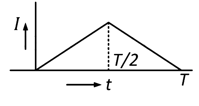
The electric current in the circuit is given as i = i o ( t / T ) i = i_o (t/T) i = i o ( t / T ) t = 0 t = 0 t = 0 t = T t = T t = T ______ .
(a) i o 2 \frac{i_o}{\sqrt{2}} 2 i o (b) i o 3 \frac{i_o}{\sqrt{3}} 3 i o (c) i o i_o i o (d) i o 6 \frac{i_o}{\sqrt{6}} 6 i o Show answer and solution
Answer: (b)
i r m s 2 = 1 T ∫ 0 T i 2 d t = 1 T ∫ 0 T i o 2 t 2 T 2 d t i_{rms}^2 = \frac{1}{T}\int_0^T i^2\,dt = \frac{1}{T}\int_0^T \frac{i_o^2 t^2}{T^2}\,dt i r m s 2 = T 1 ∫ 0 T i 2 d t = T 1 ∫ 0 T T 2 i o 2 t 2 d t = i o 2 T 3 ⋅ T 3 3 = i o 2 3 = \frac{i_o^2}{T^3}\cdot\frac{T^3}{3} = \frac{i_o^2}{3} = T 3 i o 2 ⋅ 3 T 3 = 3 i o 2 i r m s = i o 3 i_{rms} = \frac{i_o}{\sqrt{3}} i r m s = 3 i o So the answer is (b). Report a mistake Q9 MHT CET 2025 · 19 APR · SHIFT 1 Easy ☆
AC Basics: Peak, RMS & Average Values · Equation, instantaneous value and time
The instantaneous value of current in an a.c. circuit is I = 3 sin ( 50 π t + π 4 ) A I = 3 \sin\left(50\pi t + \frac{\pi}{4}\right)\text{ A} I = 3 sin ( 50 π t + 4 π ) A
(a) 1 50 s \frac{1}{50}\text{ s} 50 1 s (b) 1 100 s \frac{1}{100}\text{ s} 100 1 s (c) 1 200 s \frac{1}{200}\text{ s} 200 1 s (d) 1 600 s \frac{1}{600}\text{ s} 600 1 s Show answer and solution
Answer: (c)
Maximum when 50 π t + π 4 = π 2 50\pi t + \frac{\pi}{4} = \frac{\pi}{2} 50 π t + 4 π = 2 π 50 π t = π 4 ⇒ t = 1 200 50\pi t = \frac{\pi}{4} \Rightarrow t = \frac{1}{200} 50 π t = 4 π ⇒ t = 200 1 So the answer is (c) 1 200 \frac{1}{200} 200 1 Report a mistake Q10 JEE Main 2025 · 7 APR · SHIFT 1 Easy ☆
AC Basics: Peak, RMS & Average Values · Peak, RMS and average values
An ac current is represented as
i = 5 2 + 10 cos ( 650 π t + π 6 ) Amp i = 5\sqrt{2} + 10 \cos\left(650\pi t + \frac{\pi}{6}\right)\text{ Amp} i = 5 2 + 10 cos ( 650 π t + 6 π ) Amp
The r.m.s value of the current is
(a) 10 Amp (b) 5 2 Amp 5\sqrt{2}\text{ Amp} 5 2 Amp (c) 100 Amp (d) 50 Amp Show answer and solution
Answer: (a)
For i = I d c + I 0 cos ( ω t + ϕ ) i = I_{dc} + I_0\cos(\omega t + \phi) i = I d c + I 0 cos ( ω t + ϕ ) I r m s 2 = I d c 2 + I 0 2 2 I_{rms}^2 = I_{dc}^2 + \frac{I_0^2}{2} I r m s 2 = I d c 2 + 2 I 0 2 I r m s 2 = ( 5 2 ) 2 + 1 0 2 2 = 50 + 50 = 100 I_{rms}^2 = (5\sqrt{2})^2 + \frac{10^2}{2} = 50 + 50 = 100 I r m s 2 = ( 5 2 ) 2 + 2 1 0 2 = 50 + 50 = 100 I r m s = 10 I_{rms} = 10 I r m s = 10 So the answer is (a) 10 Amp. Report a mistake Q11 JEE Main 2025 · 4 APR · SHIFT 1 Easy ☆
AC Basics: Peak, RMS & Average Values · Peak, RMS and average values
An alternating current is represented by the equation, i = 100 2 sin ( 100 π t ) i = 100\sqrt{2} \sin(100\pi t) i = 100 2 sin ( 100 π t )
(a) 100 2 A , 100 Hz \frac{100}{\sqrt{2}}\text{ A}, 100\text{ Hz} 2 100 A , 100 Hz (b) 50 2 A , 50 Hz 50\sqrt{2}\text{ A}, 50\text{ Hz} 50 2 A , 50 Hz (c) 100 2 A , 100 Hz 100\sqrt{2}\text{ A}, 100\text{ Hz} 100 2 A , 100 Hz (d) 100 A , 50 Hz 100\text{ A}, 50\text{ Hz} 100 A , 50 Hz Show answer and solution
Answer: (d)
I r m s = I 0 2 = 100 2 2 = 100 I_{rms} = \frac{I_0}{\sqrt{2}} = \frac{100\sqrt{2}}{\sqrt{2}} = 100 I r m s = 2 I 0 = 2 100 2 = 100 ω = 100 π = 2 π f ⇒ f = 50 \omega = 100\pi = 2\pi f \Rightarrow f = 50 ω = 100 π = 2 π f ⇒ f = 50 So the answer is (d) 100 100 100 50 50 50 Report a mistake Q12 JEE Main 2025 · 3 APR · SHIFT 2 Easy ☆
AC Basics: Peak, RMS & Average Values · Peak, RMS and average values
An electric bulb rated as 100 W − 220 V 100\text{ W} - 220\text{ V} 100 W − 220 V
(a) 0.32 A (b) 0.64 A (c) 0.45 A (d) 2.2 A Show answer and solution
Answer: (b)
I r m s = P V r m s = 100 220 ≈ 0.455 I_{rms} = \frac{P}{V_{rms}} = \frac{100}{220} \approx 0.455 I r m s = V r m s P = 220 100 ≈ 0.455 I 0 = 2 I r m s = 1.414 × 0.455 ≈ 0.64 I_0 = \sqrt{2}\, I_{rms} = 1.414 \times 0.455 \approx 0.64 I 0 = 2 I r m s = 1.414 × 0.455 ≈ 0.64 So the answer is (b) 0.64 A. Report a mistake Q13 JEE Main 2025 · 24 JAN · SHIFT 1 Easy ☆
AC Basics: Peak, RMS & Average Values · Peak, RMS and average values
An alternating current is given by I = I A sin ω t + I B cos ω t I = I_A \sin \omega t + I_B \cos \omega t I = I A sin ω t + I B cos ω t
(a) I A 2 + I B 2 2 \frac{\sqrt{I_A^2 + I_B^2}}{2} 2 I A 2 + I B 2 (b) I A 2 + I B 2 2 \sqrt{\frac{I_A^2 + I_B^2}{2}} 2 I A 2 + I B 2 (c) ∣ I A + I B ∣ 2 \frac{|I_A + I_B|}{\sqrt{2}} 2 ∣ I A + I B ∣ (d) I A 2 + I B 2 \sqrt{I_A^2 + I_B^2} I A 2 + I B 2 Show answer and solution
Answer: (b)
Combine: I = I A 2 + I B 2 sin ( ω t + ϕ ) I = \sqrt{I_A^2 + I_B^2}\,\sin(\omega t + \phi) I = I A 2 + I B 2 sin ( ω t + ϕ ) Peak I 0 = I A 2 + I B 2 I_0 = \sqrt{I_A^2 + I_B^2} I 0 = I A 2 + I B 2 I r m s = I 0 2 = I A 2 + I B 2 2 I_{rms} = \frac{I_0}{\sqrt{2}} = \sqrt{\frac{I_A^2 + I_B^2}{2}} I r m s = 2 I 0 = 2 I A 2 + I B 2 So the answer is (b). Report a mistake Q14 MHT CET 2025 · 22 APR · SHIFT 2 Medium ☆
AC Basics: Peak, RMS & Average Values · Equation, instantaneous value and time
An alternating e.m.f. is given by e = e 0 sin ω t e = e_0 \sin \omega t e = e 0 sin ω t
( T = (T = ( T = sin 3 0 ∘ = 1 2 ) \sin 30^\circ = \frac{1}{2}) sin 3 0 ∘ = 2 1 )
(a) T 8 \frac{T}{8} 8 T (b) T 4 \frac{T}{4} 4 T (c) T 12 \frac{T}{12} 12 T (d) T 16 \frac{T}{16} 16 T Show answer and solution
Answer: (c)
e = e 0 2 ⇒ sin ω t = 1 2 ⇒ ω t = π 6 e = \frac{e_0}{2} \Rightarrow \sin\omega t = \frac{1}{2} \Rightarrow \omega t = \frac{\pi}{6} e = 2 e 0 ⇒ sin ω t = 2 1 ⇒ ω t = 6 π 2 π T t = π 6 ⇒ t = T 12 \frac{2\pi}{T}t = \frac{\pi}{6} \Rightarrow t = \frac{T}{12} T 2 π t = 6 π ⇒ t = 12 T So the answer is (c) T 12 \frac{T}{12} 12 T Report a mistake Q15 MHT CET 2024 · 16 MAY · SHIFT 1 Easy ☆
AC Basics: Peak, RMS & Average Values · Equation, instantaneous value and time
The alternating voltage is given by v = v 0 sin ( ω t + π 3 ) v = v_0 \sin\left(\omega t + \frac{\pi}{3}\right) v = v 0 sin ( ω t + 3 π )
(a) T 6 \frac{T}{6} 6 T (b) T 3 \frac{T}{3} 3 T (c) T 2 \frac{T}{2} 2 T (d) T 12 \frac{T}{12} 12 T Show answer and solution
Answer: (d)
Maximum when ω t + π 3 = π 2 \omega t + \frac{\pi}{3} = \frac{\pi}{2} ω t + 3 π = 2 π ω t = π 6 \omega t = \frac{\pi}{6} ω t = 6 π 2 π T t = π 6 ⇒ t = T 12 \frac{2\pi}{T}t = \frac{\pi}{6} \Rightarrow t = \frac{T}{12} T 2 π t = 6 π ⇒ t = 12 T So the answer is (d) T 12 \frac{T}{12} 12 T Report a mistake Q16 MHT CET 2024 · 4 MAY · SHIFT 2 Easy ☆
AC Basics: Peak, RMS & Average Values · Equation, instantaneous value and time
An alternating current is given by I = 100 sin ( 50 π t ) I = 100 \sin(50\pi t) I = 100 sin ( 50 π t )
(a) 50 times (b) 25 times (c) 40 times (d) 100 times Show answer and solution
Answer: (a)
ω = 50 π = 2 π f ⇒ f = 25 \omega = 50\pi = 2\pi f \Rightarrow f = 25 ω = 50 π = 2 π f ⇒ f = 25 Current becomes zero twice in every cycle. Number of zeros per second = 2 × 25 = 50 = 2 \times 25 = 50 = 2 × 25 = 50 So the answer is (a) 50 times. Report a mistake Q17 MHT CET 2024 · 2 MAY · SHIFT 1 Easy ☆
AC Basics: Peak, RMS & Average Values · Equation, instantaneous value and time
In an a.c. circuit I = 100 sin 200 π t I = 100 \sin 200\pi t I = 100 sin 200 π t
(a) 1 100 s \frac{1}{100}\text{ s} 100 1 s (b) 1 200 s \frac{1}{200}\text{ s} 200 1 s (c) 1 300 s \frac{1}{300}\text{ s} 300 1 s (d) 1 400 s \frac{1}{400}\text{ s} 400 1 s Show answer and solution
Answer: (d)
Peak when 200 π t = π 2 200\pi t = \frac{\pi}{2} 200 π t = 2 π t = 1 400 t = \frac{1}{400} t = 400 1 So the answer is (d) 1 400 \frac{1}{400} 400 1 Report a mistake Q18 JEE Main 2024 · 4 APR · SHIFT 1 Easy ☆
AC Basics: Peak, RMS & Average Values · Peak, RMS and average values
An alternating current at any instant is given by i = [ 6 + 56 sin ( 100 π t + π / 3 ) ] i = [6 + \sqrt{56} \sin(100\pi t + \pi/3)] i = [ 6 + 56 sin ( 100 π t + π /3 )]
Numerical answer type. Work it out, then open the answer.
Show answer and solution
Answer: 8
For dc + sinusoid: I r m s 2 = I d c 2 + I 0 2 2 I_{rms}^2 = I_{dc}^2 + \frac{I_0^2}{2} I r m s 2 = I d c 2 + 2 I 0 2 I r m s 2 = 6 2 + 56 2 = 36 + 28 = 64 I_{rms}^2 = 6^2 + \frac{56}{2} = 36 + 28 = 64 I r m s 2 = 6 2 + 2 56 = 36 + 28 = 64 I r m s = 8 I_{rms} = 8 I r m s = 8 Report a mistake Q19 JEE Main 2024 · 30 JAN · SHIFT 2 Medium ☆
AC Basics: Peak, RMS & Average Values · Equation, instantaneous value and time
An alternating voltage V ( t ) = 220 sin 100 π t V(t) = 220 \sin 100\pi t V ( t ) = 220 sin 100 π t 50 Ω 50\ \Omega 50 Ω
(a) 7.2 ms (b) 3.3 ms (c) 5 ms (d) 2.2 ms Show answer and solution
Answer: (b)
i = i 0 sin ( 100 π t ) i = i_0\sin(100\pi t) i = i 0 sin ( 100 π t ) 100 π t 1 = π 6 ⇒ t 1 = 1 600 100\pi t_1 = \frac{\pi}{6} \Rightarrow t_1 = \frac{1}{600} 100 π t 1 = 6 π ⇒ t 1 = 600 1 Peak: 100 π t 2 = π 2 ⇒ t 2 = 1 200 100\pi t_2 = \frac{\pi}{2} \Rightarrow t_2 = \frac{1}{200} 100 π t 2 = 2 π ⇒ t 2 = 200 1 Δ t = 1 200 − 1 600 = 1 300 \Delta t = \frac{1}{200} - \frac{1}{600} = \frac{1}{300} Δ t = 200 1 − 600 1 = 300 1 ≈ 3.3 \approx 3.3 ≈ 3.3 So the answer is (b) 3.3 ms. Report a mistake Q20 MHT CET 2023 · 13 MAY · SHIFT 2 Easy ☆
AC Basics: Peak, RMS & Average Values · Peak, RMS and average values
A group of lamps having total power rating of 1000 W 1000\text{ W} 1000 W E = 200 sin ( 310 t + 6 0 ∘ ) E = 200 \sin(310t + 60^\circ) E = 200 sin ( 310 t + 6 0 ∘ )
(a) 10 A 10\text{ A} 10 A (b) 5 2 A 5\sqrt{2}\text{ A} 5 2 A (c) 20 A 20\text{ A} 20 A (d) 10 2 A 10\sqrt{2}\text{ A} 10 2 A Show answer and solution
Answer: (b)
E r m s = 200 2 = 100 2 E_{rms} = \frac{200}{\sqrt{2}} = 100\sqrt{2} E r m s = 2 200 = 100 2 For lamps (resistive), P = E r m s I r m s P = E_{rms} I_{rms} P = E r m s I r m s I r m s = 1000 100 2 = 10 2 = 5 2 I_{rms} = \frac{1000}{100\sqrt{2}} = \frac{10}{\sqrt{2}} = 5\sqrt{2} I r m s = 100 2 1000 = 2 10 = 5 2 So the answer is (b) 5 2 5\sqrt{2} 5 2 Report a mistake Q21 MHT CET 2023 · 11 MAY · SHIFT 2 Easy ☆
AC Basics: Peak, RMS & Average Values · Peak, RMS and average values
The a.c. source of e.m.f. with instantaneous value 'e e e e = 200 sin ( 50 t ) e = 200 \sin(50t) e = 200 sin ( 50 t ) 50 Ω 50\ \Omega 50 Ω
(a) 0.2828 A (b) 2.828 A (c) 28.28 A (d) 282.8 A Show answer and solution
Answer: (b)
I 0 = e 0 R = 200 50 = 4 I_0 = \frac{e_0}{R} = \frac{200}{50} = 4 I 0 = R e 0 = 50 200 = 4 I r m s = I 0 2 = 4 1.414 ≈ 2.828 I_{rms} = \frac{I_0}{\sqrt{2}} = \frac{4}{1.414} \approx 2.828 I r m s = 2 I 0 = 1.414 4 ≈ 2.828 So the answer is (b) 2.828 A. Report a mistake Q22 JEE Main 2022 · 27 JUN · SHIFT 1 Easy ☆
AC Basics: Peak, RMS & Average Values · Equation, instantaneous value and time
The current flowing through an ac circuit is given by
I = 5 sin(120π \pi π
How long will the current take to reach the peak value starting from zero?
(a) 1 60 \frac{1}{60} 60 1 (b) 60 s (c) 1 120 \frac{1}{120} 120 1 (d) 1 240 \frac{1}{240} 240 1 Show answer and solution
Answer: (d)
ω = 120 π ⇒ f = 60 \omega = 120\pi \Rightarrow f = 60 ω = 120 π ⇒ f = 60 Zero to peak is a quarter cycle: t = 1 4 f = 1 240 t = \frac{1}{4f} = \frac{1}{240} t = 4 f 1 = 240 1 So the answer is (d) 1 240 \frac{1}{240} 240 1 Report a mistake Q23 NEET 2022 · PHASE 2 Easy ☆
AC Basics: Peak, RMS & Average Values · Peak, RMS and average values
A standard filament lamp consumes 100 W when connected to 200 V ac mains supply. The peak current through the bulb will be:
(a) 2 A (b) 0.707 A (c) 1 A (d) 1.414 A Show answer and solution
Answer: (b)
I r m s = P V r m s = 100 200 = 0.5 I_{rms} = \frac{P}{V_{rms}} = \frac{100}{200} = 0.5 I r m s = V r m s P = 200 100 = 0.5 I 0 = 2 I r m s = 1.414 × 0.5 = 0.707 I_0 = \sqrt{2}\, I_{rms} = 1.414 \times 0.5 = 0.707 I 0 = 2 I r m s = 1.414 × 0.5 = 0.707 So the answer is (b) 0.707 A. Report a mistake Q24 NEET 2022 · PHASE 1 Easy ☆
AC Basics: Peak, RMS & Average Values · Peak, RMS and average values
The peak voltage of the ac source is equal to
(a) The value of voltage supplied to the circuit (b) The rms value of the ac source (c) 2 \sqrt{2} 2 (d) 1/ 2 \sqrt{2} 2 Show answer and solution
Answer: (c)
For sinusoidal ac, V r m s = V 0 2 V_{rms} = \frac{V_0}{\sqrt{2}} V r m s = 2 V 0 So V 0 = 2 V r m s V_0 = \sqrt{2}\, V_{rms} V 0 = 2 V r m s So the answer is (c) 2 \sqrt{2} 2 Report a mistake Q25 JEE Main 2022 · 27 JUL · SHIFT 1 Easy ☆
AC Basics: Peak, RMS & Average Values · Peak, RMS and average values
A direct current of 4 A 4\text{ A} 4 A 4 A 4\text{ A} 4 A 3 Ω 3\ \Omega 3 Ω 2 Ω 2\ \Omega 2 Ω
(a) 3: 2 (b) 3: 1 (c) 3: 4 (d) 4: 3 Show answer and solution
Answer: (b)
Heat H = I r m s 2 R t H = I_{rms}^2 R t H = I r m s 2 Rt I r m s = 4 I_{rms} = 4 I r m s = 4 I r m s 2 = 4 2 2 = 8 I_{rms}^2 = \frac{4^2}{2} = 8 I r m s 2 = 2 4 2 = 8 H 1 = 16 × 3 t = 48 t H_1 = 16 \times 3\, t = 48t H 1 = 16 × 3 t = 48 t H 2 = 8 × 2 t = 16 t H_2 = 8 \times 2\, t = 16t H 2 = 8 × 2 t = 16 t H 1 : H 2 = 48 : 16 = 3 : 1 H_1 : H_2 = 48 : 16 = 3 : 1 H 1 : H 2 = 48 : 16 = 3 : 1 So the answer is (b) 3 : 1. Report a mistake Q26 MHT CET 2022 · 11 AUG · SHIFT 2 Easy ☆
AC Basics: Peak, RMS & Average Values · AC meters, waveforms and skin effect
In a full wave rectifier circuit without filter, the output current is
(a) an eddy current (b) a constant direct current (c) a sinusoidal current (d) unidirectional but not steady current Show answer and solution
Answer: (d)
A full wave rectifier flips the negative half cycles, so current flows in one direction only. Without a filter the output still rises and falls (pulsating), so it is not steady. So the answer is (d) unidirectional but not steady current. Report a mistake Q27 JEE Main 2022 · 24 JUN · SHIFT 1 Medium ☆
AC Basics: Peak, RMS & Average Values · Equation, instantaneous value and time
A resistance of 40 Ω \Omega Ω
(a) 2.5 ms (b) 1.25 ms (c) 2.5 s (d) 0.25 s Show answer and solution
Answer: (a)
Take I = I 0 cos ω t I = I_0\cos\omega t I = I 0 cos ω t cos ω t = 1 2 \cos\omega t = \frac{1}{\sqrt{2}} cos ω t = 2 1 ω t = π 4 \omega t = \frac{\pi}{4} ω t = 4 π t = T 8 t = \frac{T}{8} t = 8 T T = 1 50 T = \frac{1}{50} T = 50 1 = 20 = 20 = 20 t = 2.5 t = 2.5 t = 2.5 R R R So the answer is (a) 2.5 ms. Report a mistake Q28 JEE Main 2022 · 27 JUN · SHIFT 1 Difficult ☆
AC Basics: Peak, RMS & Average Values · Peak, RMS and average values
A 220 V, 50 Hz AC source is connected to a 25 V, 5 W lamp and an additional resistance R in series (as shown in figure) to run the lamp at its peak brightness, then the value of R (in ohm) will be _____________.
Numerical answer type. Work it out, then open the answer.
Show answer and solution
Answer: 975
Lamp at full brightness: I = P V = 5 25 = 0.2 I = \frac{P}{V} = \frac{5}{25} = 0.2 I = V P = 25 5 = 0.2 R l a m p = V 2 P = 625 5 = 125 Ω R_{lamp} = \frac{V^2}{P} = \frac{625}{5} = 125\ \Omega R l am p = P V 2 = 5 625 = 125 Ω Total resistance needed: R t o t a l = 220 0.2 = 1100 Ω R_{total} = \frac{220}{0.2} = 1100\ \Omega R t o t a l = 0.2 220 = 1100 Ω R = 1100 − 125 = 975 Ω R = 1100 - 125 = 975\ \Omega R = 1100 − 125 = 975 Ω So R = 975 Ω R = 975\ \Omega R = 975 Ω Report a mistake Q29 MHT CET 2021 · 24 SEP · SHIFT 1 Easy ☆
AC Basics: Peak, RMS & Average Values · Equation, instantaneous value and time
The peak value of an alternating emf 'e e e e = e 0 cos ω t e = e_0 \cos \omega t e = e 0 cos ω t 50 Hz 50\text{ Hz} 50 Hz t = 1 600 s t = \frac{1}{600}\text{ s} t = 600 1 s ( cos π 6 = sin π 3 = 3 2 ) \left(\cos \frac{\pi}{6} = \sin \frac{\pi}{3} = \frac{\sqrt{3}}{2}\right) ( cos 6 π = sin 3 π = 2 3 )
(a) 10 V 10\text{ V} 10 V (b) 1 3 V \frac{1}{\sqrt{3}}\text{ V} 3 1 V (c) 5 V 5\text{ V} 5 V (d) 5 3 V 5\sqrt{3}\text{ V} 5 3 V Show answer and solution
Answer: (d)
ω t = 2 π × 50 × 1 600 = π 6 \omega t = 2\pi \times 50 \times \frac{1}{600} = \frac{\pi}{6} ω t = 2 π × 50 × 600 1 = 6 π e = 10 cos π 6 = 10 × 3 2 = 5 3 e = 10\cos\frac{\pi}{6} = 10 \times \frac{\sqrt{3}}{2} = 5\sqrt{3} e = 10 cos 6 π = 10 × 2 3 = 5 3 So the answer is (d) 5 3 5\sqrt{3} 5 3 Report a mistake Q30 MHT CET 2021 · 21 SEP · SHIFT 1 Easy ☆
AC Basics: Peak, RMS & Average Values · Equation, instantaneous value and time
An alternating voltge is represented by V = 80 sin ( 100 π t ) cos ( 100 π t ) V = 80 \sin(100\pi t) \cos(100\pi t) V = 80 sin ( 100 π t ) cos ( 100 π t )
(a) 20 V 20\text{ V} 20 V (b) 40 V 40\text{ V} 40 V (c) 30 V 30\text{ V} 30 V (d) 50 V 50\text{ V} 50 V Show answer and solution
Answer: (b)
Use 2 sin θ cos θ = sin 2 θ 2\sin\theta\cos\theta = \sin 2\theta 2 sin θ cos θ = sin 2 θ V = 40 × 2 sin ( 100 π t ) cos ( 100 π t ) = 40 sin ( 200 π t ) V = 40 \times 2\sin(100\pi t)\cos(100\pi t) = 40\sin(200\pi t) V = 40 × 2 sin ( 100 π t ) cos ( 100 π t ) = 40 sin ( 200 π t ) Peak voltage = 40 = 40 = 40 So the answer is (b) 40 40 40 Report a mistake Q31 JEE Main 2021 · 18 MAR · SHIFT 1 Easy ☆
AC Basics: Peak, RMS & Average Values · Equation, instantaneous value and time
An AC source rated 220 V, 50 Hz is connected to a resistor. The time taken by the current to change from its maximum to the rms value is:
(a) 2.5 ms (b) 25 ms (c) 2.5 s (d) 0.25 ms Show answer and solution
Answer: (a)
Take I = I 0 cos ω t I = I_0\cos\omega t I = I 0 cos ω t t = 0 t = 0 t = 0 rms value: I 0 cos ω t = I 0 2 ⇒ ω t = π 4 I_0\cos\omega t = \frac{I_0}{\sqrt{2}} \Rightarrow \omega t = \frac{\pi}{4} I 0 cos ω t = 2 I 0 ⇒ ω t = 4 π t = T 8 t = \frac{T}{8} t = 8 T T = 1 50 = 20 T = \frac{1}{50} = 20 T = 50 1 = 20 t = 20 8 = 2.5 t = \frac{20}{8} = 2.5 t = 8 20 = 2.5 So the answer is (a) 2.5 ms. Report a mistake Q32 MHT CET 2021 · 24 SEP · SHIFT 2 Medium ☆
AC Basics: Peak, RMS & Average Values · Equation, instantaneous value and time
An alternating e.m.f. is e = e 0 sin ω t e = e_0 \sin \omega t e = e 0 sin ω t e e e T = T = T = sin 3 0 ∘ = 0.5 \sin 30^\circ = 0.5 sin 3 0 ∘ = 0.5
(a) T 12 \frac{T}{12} 12 T (b) T 16 \frac{T}{16} 16 T (c) T 4 \frac{T}{4} 4 T (d) T 8 \frac{T}{8} 8 T Show answer and solution
Answer: (a)
e = e 0 2 ⇒ sin ω t = 1 2 ⇒ ω t = π 6 e = \frac{e_0}{2} \Rightarrow \sin\omega t = \frac{1}{2} \Rightarrow \omega t = \frac{\pi}{6} e = 2 e 0 ⇒ sin ω t = 2 1 ⇒ ω t = 6 π 2 π T t = π 6 ⇒ t = T 12 \frac{2\pi}{T}t = \frac{\pi}{6} \Rightarrow t = \frac{T}{12} T 2 π t = 6 π ⇒ t = 12 T So the answer is (a) T 12 \frac{T}{12} 12 T Report a mistake Q33 MHT CET 2021 · 21 SEP · SHIFT 2 Medium ☆
AC Basics: Peak, RMS & Average Values · Equation, instantaneous value and time
The instantaneous value of an alternating current is given by i = 50 sin ( 100 π t ) i = 50 \sin(100\pi t) i = 50 sin ( 100 π t ) 25 A 25\text{ A} 25 A ( sin 3 0 ∘ = 0.5 ) (\sin 30^\circ = 0.5) ( sin 3 0 ∘ = 0.5 )
(a) 1 300 s \frac{1}{300}\text{ s} 300 1 s (b) 1 100 s \frac{1}{100}\text{ s} 100 1 s (c) 1 200 s \frac{1}{200}\text{ s} 200 1 s (d) 1 600 s \frac{1}{600}\text{ s} 600 1 s Show answer and solution
Answer: (d)
25 = 50 sin ( 100 π t ) ⇒ sin ( 100 π t ) = 1 2 25 = 50\sin(100\pi t) \Rightarrow \sin(100\pi t) = \frac{1}{2} 25 = 50 sin ( 100 π t ) ⇒ sin ( 100 π t ) = 2 1 100 π t = π 6 ⇒ t = 1 600 100\pi t = \frac{\pi}{6} \Rightarrow t = \frac{1}{600} 100 π t = 6 π ⇒ t = 600 1 So the answer is (d) 1 600 \frac{1}{600} 600 1 Report a mistake Q34 JEE Main 2021 · 25 JUL · SHIFT 2 Medium ☆
AC Basics: Peak, RMS & Average Values · Equation, instantaneous value and time
A 10 Ω \Omega Ω − - −
(a) 2.5 ms (b) 1.5 ms (c) 3.0 ms (d) 4.5 ms Show answer and solution
Answer: (a)
Take I = I 0 cos ω t I = I_0\cos\omega t I = I 0 cos ω t cos ω t = 1 2 \cos\omega t = \frac{1}{\sqrt{2}} cos ω t = 2 1 ω t = π 4 \omega t = \frac{\pi}{4} ω t = 4 π t = T 8 t = \frac{T}{8} t = 8 T T = 1 50 T = \frac{1}{50} T = 50 1 = 20 = 20 = 20 t = 2.5 t = 2.5 t = 2.5 R R R So the answer is (a) 2.5 ms. Report a mistake Q35 JEE Main 2021 · 17 MAR · SHIFT 1 Medium ☆
AC Basics: Peak, RMS & Average Values · Peak, RMS and average values
An AC current is given by I = I1 sinω \omega ω ω \omega ω
(a) I 1 + I 2 2 \frac{I_1 + I_2}{\sqrt{2}} 2 I 1 + I 2 (b) I 1 2 − I 2 2 2 \sqrt{\frac{I_1^2 - I_2^2}{2}} 2 I 1 2 − I 2 2 (c) I 1 2 + I 2 2 2 \sqrt{\frac{I_1^2 + I_2^2}{2}} 2 I 1 2 + I 2 2 (d) I 1 + I 2 2 2 \frac{I_1 + I_2}{2\sqrt{2}} 2 2 I 1 + I 2 Show answer and solution
Answer: (c)
A hot wire ammeter reads the rms value: I r m s 2 = ⟨ I 2 ⟩ I_{rms}^2 = \langle I^2 \rangle I r m s 2 = ⟨ I 2 ⟩ I 2 = I 1 2 sin 2 ω t + I 2 2 cos 2 ω t + 2 I 1 I 2 sin ω t cos ω t I^2 = I_1^2\sin^2\omega t + I_2^2\cos^2\omega t + 2I_1I_2\sin\omega t\cos\omega t I 2 = I 1 2 sin 2 ω t + I 2 2 cos 2 ω t + 2 I 1 I 2 sin ω t cos ω t Over a cycle ⟨ sin 2 ⟩ = ⟨ cos 2 ⟩ = 1 2 \langle\sin^2\rangle = \langle\cos^2\rangle = \frac{1}{2} ⟨ sin 2 ⟩ = ⟨ cos 2 ⟩ = 2 1 ⟨ sin ω t cos ω t ⟩ = 0 \langle\sin\omega t\cos\omega t\rangle = 0 ⟨ sin ω t cos ω t ⟩ = 0 I r m s = I 1 2 + I 2 2 2 I_{rms} = \sqrt{\frac{I_1^2 + I_2^2}{2}} I r m s = 2 I 1 2 + I 2 2 So the answer is (c). Report a mistake Q36 JEE Main 2021 · 26 FEB · SHIFT 1 Medium ☆
AC Basics: Peak, RMS & Average Values · Peak, RMS and average values
An alternating current is given by the equation i = i1 sin ω \omega ω ω \omega ω
(a) 1 2 ( i 1 2 + i 2 2 ) 1 2 \frac{1}{\sqrt{2}}\left(i_1^2 + i_2^2\right)^{\frac{1}{2}} 2 1 ( i 1 2 + i 2 2 ) 2 1 (b) 1 2 ( i 1 + i 2 ) \frac{1}{\sqrt{2}}(i_1 + i_2) 2 1 ( i 1 + i 2 ) (c) 1 2 ( i 1 + i 2 ) 2 \frac{1}{\sqrt{2}}(i_1 + i_2)^2 2 1 ( i 1 + i 2 ) 2 (d) 1 2 ( i 1 2 + i 2 2 ) 1 2 \frac{1}{2}\left(i_1^2 + i_2^2\right)^{\frac{1}{2}} 2 1 ( i 1 2 + i 2 2 ) 2 1 Show answer and solution
Answer: (a)
i r m s 2 = ⟨ i 2 ⟩ = i 1 2 ⟨ sin 2 ω t ⟩ + i 2 2 ⟨ cos 2 ω t ⟩ + 2 i 1 i 2 ⟨ sin ω t cos ω t ⟩ i_{rms}^2 = \langle i^2 \rangle = i_1^2\langle\sin^2\omega t\rangle + i_2^2\langle\cos^2\omega t\rangle + 2i_1i_2\langle\sin\omega t\cos\omega t\rangle i r m s 2 = ⟨ i 2 ⟩ = i 1 2 ⟨ sin 2 ω t ⟩ + i 2 2 ⟨ cos 2 ω t ⟩ + 2 i 1 i 2 ⟨ sin ω t cos ω t ⟩ = i 1 2 2 + i 2 2 2 + 0 = \frac{i_1^2}{2} + \frac{i_2^2}{2} + 0 = 2 i 1 2 + 2 i 2 2 + 0 i r m s = 1 2 ( i 1 2 + i 2 2 ) 1 / 2 i_{rms} = \frac{1}{\sqrt{2}}\left(i_1^2 + i_2^2\right)^{1/2} i r m s = 2 1 ( i 1 2 + i 2 2 ) 1/2 So the answer is (a). Report a mistake Q37 JEE Main 2021 · 27 AUG · SHIFT 1 Difficult ☆
AC Basics: Peak, RMS & Average Values · Peak, RMS and average values
The alternating current is given by i = { 42 sin ( 2 π T t ) + 10 } A i = \left\{\sqrt{42} \sin\left(\frac{2\pi}{T} t\right) + 10\right\} A i = { 42 sin ( T 2 π t ) + 10 } A
The r.m.s. value of of this current is ................. A.
Numerical answer type. Work it out, then open the answer.
Show answer and solution
Answer: 11
i 2 = 42 sin 2 ω t + 20 42 sin ω t + 100 i^2 = 42\sin^2\omega t + 20\sqrt{42}\sin\omega t + 100 i 2 = 42 sin 2 ω t + 20 42 sin ω t + 100 Over a cycle ⟨ sin 2 ω t ⟩ = 1 2 \langle\sin^2\omega t\rangle = \frac{1}{2} ⟨ sin 2 ω t ⟩ = 2 1 ⟨ sin ω t ⟩ = 0 \langle\sin\omega t\rangle = 0 ⟨ sin ω t ⟩ = 0 i r m s 2 = 21 + 0 + 100 = 121 i_{rms}^2 = 21 + 0 + 100 = 121 i r m s 2 = 21 + 0 + 100 = 121 i r m s = 11 i_{rms} = 11 i r m s = 11 Report a mistake Q38 MHT CET 2019 · 2 MAY · SHIFT 2 Easy ☆
AC Basics: Peak, RMS & Average Values · Equation, instantaneous value and time
An alternating voltage is given by E = 100 sin ( ω t + π 6 ) V E = 100 \sin\left(\omega t + \frac{\pi}{6}\right)\text{ V} E = 100 sin ( ω t + 6 π ) V T = T = T =
(a) T 12 \frac{T}{12} 12 T (b) T 2 \frac{T}{2} 2 T (c) T 6 \frac{T}{6} 6 T (d) T 3 \frac{T}{3} 3 T Show answer and solution
Answer: (c)
Maximum when ω t + π 6 = π 2 \omega t + \frac{\pi}{6} = \frac{\pi}{2} ω t + 6 π = 2 π ω t = π 3 \omega t = \frac{\pi}{3} ω t = 3 π 2 π T t = π 3 ⇒ t = T 6 \frac{2\pi}{T}t = \frac{\pi}{3} \Rightarrow t = \frac{T}{6} T 2 π t = 3 π ⇒ t = 6 T So the answer is (c) T 6 \frac{T}{6} 6 T Report a mistake Q39 NEET 2019 Easy ☆
AC Basics: Peak, RMS & Average Values · AC meters, waveforms and skin effect
The variation of EMF with time for four types of generators are shown in the figures. Which amongst them can be called AC?
(a) Only (a) (b) (a) and (d) (c) (a), (b), (c), (d) (d) (a) and (b) Show answer and solution
Answer: (c)
AC means the emf reverses its direction (sign) periodically. In all four graphs (a), (b), (c), (d) the emf takes both positive and negative values, so each one alternates. So the answer is (c) (a), (b), (c), (d). Report a mistake Q40 JEE Main 2019 · 8 APR · SHIFT 1 Medium ☆
AC Basics: Peak, RMS & Average Values · Equation, instantaneous value and time
An alternating voltage v(t) = 220 sin 100 π \pi π Ω \Omega Ω
(a) 5 ms (b) 2.2 ms (c) 3.3 ms (d) 7.2 ms Show answer and solution
Answer: (c)
i = i 0 sin ( 100 π t ) i = i_0\sin(100\pi t) i = i 0 sin ( 100 π t ) 100 π t 1 = π 6 ⇒ t 1 = 1 600 100\pi t_1 = \frac{\pi}{6} \Rightarrow t_1 = \frac{1}{600} 100 π t 1 = 6 π ⇒ t 1 = 600 1 Peak: 100 π t 2 = π 2 ⇒ t 2 = 1 200 100\pi t_2 = \frac{\pi}{2} \Rightarrow t_2 = \frac{1}{200} 100 π t 2 = 2 π ⇒ t 2 = 200 1 Δ t = 1 200 − 1 600 = 1 300 \Delta t = \frac{1}{200} - \frac{1}{600} = \frac{1}{300} Δ t = 200 1 − 600 1 = 300 1 ≈ 3.3 \approx 3.3 ≈ 3.3 So the answer is (c) 3.3 ms. Report a mistake Q41 JEE Main 2015 · 11 APR · SHIFT 1 Easy ☆
AC Basics: Peak, RMS & Average Values · AC meters, waveforms and skin effect
The AC voltage across a resistance can be measured using a:
(a) potentiometer (b) moving coil galvanometer (c) moving magnet galvanometer (d) hot wire voltmeter Show answer and solution
Answer: (d)
A hot wire instrument works on heating effect, H ∝ I 2 H \propto I^2 H ∝ I 2 Potentiometer and moving coil / moving magnet galvanometers respond to the average (dc) value, which is zero for ac. So the answer is (d) hot wire voltmeter. Report a mistake Q42 NEET 2011 · AIPMT · MAINS Easy ☆
AC Basics: Peak, RMS & Average Values · Peak, RMS and average values
The r.m.s. value of potential difference V shown in the figure is
(a) V 0 3 \frac{V_0}{\sqrt{3}} 3 V 0 (b) V0 (c) V 0 2 \frac{V_0}{\sqrt{2}} 2 V 0 (d) V 0 2 \frac{V_0}{2} 2 V 0 Show answer and solution
Answer: (c)
V r m s 2 = V_{rms}^2 = V r m s 2 = V 2 V^2 V 2 V = V 0 V = V_0 V = V 0 0 0 0 T 2 \frac{T}{2} 2 T V = 0 V = 0 V = 0 T 2 \frac{T}{2} 2 T T T T V r m s 2 = V 0 2 ⋅ T 2 + 0 T = V 0 2 2 V_{rms}^2 = \frac{V_0^2 \cdot \frac{T}{2} + 0}{T} = \frac{V_0^2}{2} V r m s 2 = T V 0 2 ⋅ 2 T + 0 = 2 V 0 2 V r m s = V 0 2 V_{rms} = \frac{V_0}{\sqrt{2}} V r m s = 2 V 0 Report a mistake Q43 JEE Main 2004 · AIEEE Easy ☆
AC Basics: Peak, RMS & Average Values · AC meters, waveforms and skin effect
Alternating current can not be measured by D.C. \text{D.C.} D.C.
(a) Average value of current for complete cycle is zero (b) A.C. \text{A.C.} A.C. (c) A.C. \text{A.C.} A.C. D.C. \text{D.C.} D.C. (d) D.C. \text{D.C.} D.C. Show answer and solution
Answer: (a)
A D.C. ammeter's deflection is proportional to the average current. For a complete cycle of AC the average current is zero, so it shows no reading. So the answer is (a). Report a mistake Q44 NEET 1994 · AIPMT Easy ☆
AC Basics: Peak, RMS & Average Values · Peak, RMS and average values
In an A.C. circuit, I rms I_{\text{rms}} I rms I 0 I_0 I 0
(a) I rms = π I 0 I_{\text{rms}} = \pi I_0 I rms = π I 0 (b) I rms = 2 I 0 I_{\text{rms}} = \sqrt{2}\, I_0 I rms = 2 I 0 (c) I rms = I 0 / π I_{\text{rms}} = I_0/\pi I rms = I 0 / π (d) I rms = I 0 / 2 I_{\text{rms}} = I_0/\sqrt{2} I rms = I 0 / 2 Show answer and solution
Answer: (d)
For sinusoidal current, mean of sin 2 ω t \sin^2\omega t sin 2 ω t 1 2 \frac{1}{2} 2 1 I r m s = I 0 2 2 = I 0 2 I_{rms} = \sqrt{\frac{I_0^2}{2}} = \frac{I_0}{\sqrt{2}} I r m s = 2 I 0 2 = 2 I 0 So the answer is (d) I r m s = I 0 / 2 I_{rms} = I_0/\sqrt{2} I r m s = I 0 / 2 Report a mistake Q45 NEET 1994 · AIPMT Easy Old syllabus ☆
AC Basics: Peak, RMS & Average Values · AC meters, waveforms and skin effect
Two cables of copper are of equal lengths. One of them has a single wire of area of cross-section A A A A / 10 A/10 A /10
(a) only multiple strands for A.C., either for D.C. (b) only multiple strands for A.C., only single strand for D.C. (c) only single strand for D.C., either for A.C. (d) only single strand for A.C., either for D.C. Show answer and solution
Answer: (a)
Due to skin effect, AC flows mostly near the surface of a conductor. Ten thin strands give much more surface area than one thick wire, so they suit AC. DC spreads over the whole cross-section; both cables have the same total area A A A So the answer is (a). Report a mistake Q46 MHT CET 2026 · 20 MAY · SHIFT 1 Easy ☆
Pure R, L and C Circuits · Phase relations in pure R, L and C
The correct phasor diagram for an a.c. circuit containing only pure capacitor.
Show answer and solution
Answer: (b)
In a pure capacitor the current leads the emf by π 2 \frac{\pi}{2} 2 π Phasors rotate anticlockwise, so e e e 9 0 ∘ 90^\circ 9 0 ∘ i i i In figure (2), i i i e e e e e e 9 0 ∘ 90^\circ 9 0 ∘ i i i So the answer is (b), figure (2). Report a mistake Q47 MHT CET 2026 · 19 APR · SHIFT 2 Easy ☆
Pure R, L and C Circuits · Phase relations in pure R, L and C
When a.c. source is connected across a pure capacitor, the correct phase relation between current and emf is shown in figure.
Show answer and solution
Answer: (c)
e I (leads) 90° For a pure capacitor, current leads emf by π 2 \frac{\pi}{2} 2 π With anticlockwise rotation, I c I_c I c 9 0 ∘ 90^\circ 9 0 ∘ e c e_c e c Figure (B): e c e_c e c I c I_c I c I c I_c I c 9 0 ∘ 90^\circ 9 0 ∘ So the answer is (c), figure (B). Report a mistake Q48 MHT CET 2026 · 17 APR · SHIFT 2 Easy ☆
Pure R, L and C Circuits · Phase relations in pure R, L and C
In an a.c. circuit with pure capacitance 'C' and a.c. source E = E 0 sin ω t E = E_0 \sin \omega t E = E 0 sin ω t
(a) I = E 0 ω C ⋅ sin ( ω t ) I = E_0 \omega C \cdot \sin(\omega t) I = E 0 ω C ⋅ sin ( ω t ) (b) I = E 0 ω C sin ( ω t + π 2 ) I = E_0 \omega C \sin\left(\omega t + \frac{\pi}{2}\right) I = E 0 ω C sin ( ω t + 2 π ) (c) I = E 0 ω C sin ( ω t ) I = \frac{E_0}{\omega C} \sin(\omega t) I = ω C E 0 sin ( ω t ) (d) I = E 0 ω C sin ( ω t + π 2 ) I = \frac{E_0}{\omega C} \sin\left(\omega t + \frac{\pi}{2}\right) I = ω C E 0 sin ( ω t + 2 π ) Show answer and solution
Answer: (b)
Charge q = C E 0 sin ω t q = CE_0\sin\omega t q = C E 0 sin ω t I = d q d t = E 0 ω C cos ω t I = \frac{dq}{dt} = E_0\omega C\cos\omega t I = d t d q = E 0 ω C cos ω t cos ω t = sin ( ω t + π 2 ) \cos\omega t = \sin\left(\omega t + \frac{\pi}{2}\right) cos ω t = sin ( ω t + 2 π ) I = E 0 ω C sin ( ω t + π 2 ) I = E_0\omega C\sin\left(\omega t + \frac{\pi}{2}\right) I = E 0 ω C sin ( ω t + 2 π ) So the answer is (b). Report a mistake Q49 MHT CET 2026 · 15 MAY · SHIFT 1 Easy ☆
Pure R, L and C Circuits · Inductive reactance
Which one of the following graph represents the correct variation of inductive reactance (X L X_L X L ω \omega ω
Show answer and solution
Answer: (b)
X L = ω L X_L = \omega L X L = ω L X L ∝ ω X_L \propto \omega X L ∝ ω The graph is a straight line through the origin. So the answer is (b), graph B. Report a mistake Q50 MHT CET 2026 · 13 MAY · SHIFT 2 Easy ☆
Pure R, L and C Circuits · Inductive reactance
An inductance of negligible resistance, whose reactance is 120 Ω 120\ \Omega 120 Ω 200 200 200 240 240 240 60 60 60
(a) 6.66 6.66 6.66 (b) 6.60 6.60 6.60 (c) 5.45 5.45 5.45 (d) 54.5 54.5 54.5 Show answer and solution
Answer: (a)
X L = 2 π f L ∝ f X_L = 2\pi fL \propto f X L = 2 π f L ∝ f X L = 120 × 60 200 = 36 Ω X_L = 120 \times \frac{60}{200} = 36\ \Omega X L = 120 × 200 60 = 36 Ω I = V X L = 240 36 = 6.67 I = \frac{V}{X_L} = \frac{240}{36} = 6.67 I = X L V = 36 240 = 6.67 So the answer is (a) 6.66 6.66 6.66 Report a mistake Q51 MHT CET 2026 · 15 APR · SHIFT 1 Easy ☆
Pure R, L and C Circuits · Inductive reactance
A coil has inductive reactance 3 3 3
(a) zero (b) 3 3 3 (c) infinite (d) 1.5 1.5 1.5 Show answer and solution
Answer: (c)
For a.c.: X L = ω L X_L = \omega L X L = ω L For d.c.: ω = 0 \omega = 0 ω = 0 X L = 0 X_L = 0 X L = 0 Ratio = ω L 0 = ∞ = \frac{\omega L}{0} = \infty = 0 ω L = ∞ So the answer is (c) infinite. Report a mistake Q52 MHT CET 2026 · 15 MAY · SHIFT 2 Easy ☆
Pure R, L and C Circuits · Capacitive reactance
An alternating voltage V = 200 2 sin ( 100 t ) V = 200\sqrt{2} \sin(100t) V = 200 2 sin ( 100 t ) 1 μ F 1\ \mu F 1 μ F
(a) 5 5 5 (b) 10 10 10 (c) 15 15 15 (d) 20 20 20 Show answer and solution
Answer: (d)
ω = 100 \omega = 100 ω = 100 X C = 1 ω C = 1 100 × 1 0 − 6 = 1 0 4 Ω X_C = \frac{1}{\omega C} = \frac{1}{100 \times 10^{-6}} = 10^4\ \Omega X C = ω C 1 = 100 × 1 0 − 6 1 = 1 0 4 Ω V r m s = 200 2 2 = 200 V_{rms} = \frac{200\sqrt{2}}{\sqrt{2}} = 200 V r m s = 2 200 2 = 200 I r m s = 200 1 0 4 = 0.02 I_{rms} = \frac{200}{10^4} = 0.02 I r m s = 1 0 4 200 = 0.02 = 20 = 20 = 20 So the answer is (d) 20. Report a mistake Q53 MHT CET 2026 · 15 MAY · SHIFT 1 Easy ☆
Pure R, L and C Circuits · Capacitive reactance
An alternating voltage V = 200 2 sin ( 100 t ) V = 200\sqrt{2} \sin(100t) V = 200 2 sin ( 100 t ) 1 μ F 1\ \mu F 1 μ F
(a) 5 5 5 (b) 10 10 10 (c) 15 15 15 (d) 20 20 20 Show answer and solution
Answer: (d)
X C = 1 ω C = 1 100 × 1 0 − 6 = 1 0 4 Ω X_C = \frac{1}{\omega C} = \frac{1}{100 \times 10^{-6}} = 10^4\ \Omega X C = ω C 1 = 100 × 1 0 − 6 1 = 1 0 4 Ω V r m s = 200 V_{rms} = 200 V r m s = 200 I r m s = 200 1 0 4 = 20 I_{rms} = \frac{200}{10^4} = 20 I r m s = 1 0 4 200 = 20 So the answer is (d) 20 mA. Report a mistake Q54 MHT CET 2026 · 14 MAY · SHIFT 1 Easy ☆
Pure R, L and C Circuits · Capacitive reactance
In an a.c. circuit, if the frequency is doubled, what happens to the capacitive reactance (X c X_c X c I I I
(a) X c X_c X c I I I (b) X c X_c X c I I I (c) Both X c X_c X c I I I (d) Both X c X_c X c I I I Show answer and solution
Answer: (a)
X C = 1 2 π f C ∝ 1 f X_C = \frac{1}{2\pi fC} \propto \frac{1}{f} X C = 2 π f C 1 ∝ f 1 f f f X C X_C X C I = V X C I = \frac{V}{X_C} I = X C V X C X_C X C I I I So the answer is (a). Report a mistake Q55 MHT CET 2026 · 13 MAY · SHIFT 2 Easy ☆
Pure R, L and C Circuits · Capacitive reactance
An alternating voltage V = 200 2 sin ( 100 t ) V = 200\sqrt{2} \sin(100t) V = 200 2 sin ( 100 t ) 1 μ 1\ \mu 1 μ
(a) 10 10 10 (b) 20 20 20 (c) 40 40 40 (d) 80 80 80 Show answer and solution
Answer: (b)
X C = 1 ω C = 1 100 × 1 0 − 6 = 1 0 4 Ω X_C = \frac{1}{\omega C} = \frac{1}{100 \times 10^{-6}} = 10^4\ \Omega X C = ω C 1 = 100 × 1 0 − 6 1 = 1 0 4 Ω V r m s = 200 2 2 = 200 V_{rms} = \frac{200\sqrt{2}}{\sqrt{2}} = 200 V r m s = 2 200 2 = 200 I r m s = 200 1 0 4 = 20 I_{rms} = \frac{200}{10^4} = 20 I r m s = 1 0 4 200 = 20 So the answer is (b) 20 mA. Report a mistake Q56 MHT CET 2026 · 12 MAY · SHIFT 2 Easy ☆
Pure R, L and C Circuits · Capacitive reactance
A capacitor of 10 μ F 10\ \mu F 10 μ F 2 × 1 0 − 3 Ω 2 \times 10^{-3}\ \Omega 2 × 1 0 − 3 Ω
(a) 25 π MHz \frac{25}{\pi}\text{ MHz} π 25 MHz (b) 25 π Hz \frac{25}{\pi}\text{ Hz} π 25 Hz (c) 2.5 2.5 2.5 (d) 2.5 π MHz \frac{2.5}{\pi}\text{ MHz} π 2.5 MHz Show answer and solution
Answer: (a)
X C = 1 2 π f C ⇒ f = 1 2 π C X C X_C = \frac{1}{2\pi fC} \Rightarrow f = \frac{1}{2\pi CX_C} X C = 2 π f C 1 ⇒ f = 2 π C X C 1 f = 1 2 π × 10 × 1 0 − 6 × 2 × 1 0 − 3 = 1 4 π × 1 0 − 8 = 25 × 1 0 6 π f = \frac{1}{2\pi \times 10\times10^{-6} \times 2\times10^{-3}} = \frac{1}{4\pi\times10^{-8}} = \frac{25\times10^{6}}{\pi} f = 2 π × 10 × 1 0 − 6 × 2 × 1 0 − 3 1 = 4 π × 1 0 − 8 1 = π 25 × 1 0 6 So the answer is (a) 25 π \frac{25}{\pi} π 25 Report a mistake Q57 MHT CET 2026 · 19 APR · SHIFT 1 Easy ☆
Pure R, L and C Circuits · Capacitive reactance
An alternating voltage e = 150 2 sin 100 t e = 150\sqrt{2} \sin 100t e = 150 2 sin 100 t 2 μ 2\ \mu 2 μ
(a) 300 300 300 (b) 150 150 150 (c) 30 30 30 (d) 15 15 15 Show answer and solution
Answer: (c)
ω = 100 \omega = 100 ω = 100 X C = 1 ω C = 1 100 × 2 × 1 0 − 6 = 5000 Ω X_C = \frac{1}{\omega C} = \frac{1}{100 \times 2\times10^{-6}} = 5000\ \Omega X C = ω C 1 = 100 × 2 × 1 0 − 6 1 = 5000 Ω V r m s = 150 2 2 = 150 V_{rms} = \frac{150\sqrt{2}}{\sqrt{2}} = 150 V r m s = 2 150 2 = 150 I r m s = 150 5000 = 0.03 I_{rms} = \frac{150}{5000} = 0.03 I r m s = 5000 150 = 0.03 = 30 = 30 = 30 So the answer is (c) 30 mA. Report a mistake Q58 MHT CET 2026 · 17 APR · SHIFT 2 Easy ☆
Pure R, L and C Circuits · Capacitive reactance
In LCR circuit, at a particular angular frequency the capacitive reactance and inductive reactance is same. If the angular frequency is doubled, the ratio of the reactance of the capacitor to that of the inductor will be
(a) 1 4 \frac{1}{4} 4 1 (b) 1 2 \frac{1}{2} 2 1 (c) 1 1 1 (d) 4 4 4 Show answer and solution
Answer: (a)
X C = 1 ω C X_C = \frac{1}{\omega C} X C = ω C 1 X L = ω L X_L = \omega L X L = ω L X C X L = 1 ω 2 L C ∝ 1 ω 2 \frac{X_C}{X_L} = \frac{1}{\omega^2 LC} \propto \frac{1}{\omega^2} X L X C = ω 2 L C 1 ∝ ω 2 1 Initially X C X L = 1 \frac{X_C}{X_L} = 1 X L X C = 1 ω \omega ω X C ′ X L ′ = 1 2 2 = 1 4 \frac{X_C'}{X_L'} = \frac{1}{2^2} = \frac{1}{4} X L ′ X C ′ = 2 2 1 = 4 1 So the answer is (a) 1 4 \frac{1}{4} 4 1 Report a mistake Q59 MHT CET 2026 · 15 APR · SHIFT 1 Easy ☆
Pure R, L and C Circuits · Capacitive reactance
Determine the frequency for which a 10 μ 10\ \mu 10 μ 2 × 1 0 − 3 Ω 2 \times 10^{-3}\ \Omega 2 × 1 0 − 3 Ω
(a) 25 π \frac{25}{\pi} π 25 (b) 20 π \frac{20}{\pi} π 20 (c) 2 × 1 0 − 3 2 \times 10^{-3} 2 × 1 0 − 3 (d) 10 π 10\pi 10 π π π \pi \quad \pi π π Show answer and solution
Answer: (a)
X C = 1 2 π f C ⇒ f = 1 2 π C X C X_C = \frac{1}{2\pi f C} \Rightarrow f = \frac{1}{2\pi C X_C} X C = 2 π f C 1 ⇒ f = 2 π C X C 1 f = 1 2 π × 10 × 1 0 − 6 × 2 × 1 0 − 3 = 1 4 π × 1 0 − 8 = 25 × 1 0 6 π f = \frac{1}{2\pi \times 10 \times 10^{-6} \times 2 \times 10^{-3}} = \frac{1}{4\pi \times 10^{-8}} = \frac{25 \times 10^{6}}{\pi} f = 2 π × 10 × 1 0 − 6 × 2 × 1 0 − 3 1 = 4 π × 1 0 − 8 1 = π 25 × 1 0 6 So the answer is (a) 25 π \frac{25}{\pi} π 25 Report a mistake Q60 MHT CET 2026 · 15 MAY · SHIFT 2 Medium ☆
Pure R, L and C Circuits · Capacitive reactance
Same current is flowing in two AC circuits. First contains only inductance and second contains only capacitance. If frequency of AC is increased for both, the current will
(a) increase in first circuit and decrease in second (b) increase in both circuits (c) decrease in both circuits (d) decrease in first circuit and increase in second Show answer and solution
Answer: (d)
Inductor: I = V 2 π f L I = \frac{V}{2\pi f L} I = 2 π f L V f f f Capacitor: I = V ( 2 π f C ) I = V(2\pi f C) I = V ( 2 π f C ) f f f So the answer is (d): decreases in the first circuit and increases in the second. Report a mistake Q61 MHT CET 2025 · 25 APR · SHIFT 1 Easy ☆
Pure R, L and C Circuits · Phase relations in pure R, L and C
An a. c. voltage is applied to pure inductor. The current in the inductor
(a) leads the voltage by ( π 4 ) c \left(\frac{\pi}{4}\right)^c ( 4 π ) c (b) leads the voltage by ( π 2 ) c \left(\frac{\pi}{2}\right)^c ( 2 π ) c (c) lags behind the voltage by ( π 2 ) c \left(\frac{\pi}{2}\right)^c ( 2 π ) c (d) lags behind the voltage by ( 3 π 4 ) c \left(\frac{3\pi}{4}\right)^c ( 4 3 π ) c Show answer and solution
Answer: (c)
For a pure inductor, E = L d I d t E = L\frac{dI}{dt} E = L d t d I E = E 0 sin ω t E = E_0\sin\omega t E = E 0 sin ω t I = − E 0 ω L cos ω t = E 0 ω L sin ( ω t − π 2 ) I = -\frac{E_0}{\omega L}\cos\omega t = \frac{E_0}{\omega L}\sin\left(\omega t - \frac{\pi}{2}\right) I = − ω L E 0 cos ω t = ω L E 0 sin ( ω t − 2 π ) Current lags the voltage by π 2 \frac{\pi}{2} 2 π So the answer is (c). Report a mistake Q62 MHT CET 2025 · 23 APR · SHIFT 1 Easy ☆
Pure R, L and C Circuits · Phase relations in pure R, L and C
An a. c. source is connected across a pure inductor. Which one of the following figures shows the correct phase relation between the current and e.m.f.?
Show answer and solution
Answer: (b)
In a pure inductor the current lags the emf by π 2 \frac{\pi}{2} 2 π With anticlockwise rotation, i L i_L i L 9 0 ∘ 90^\circ 9 0 ∘ e L e_L e L Figure B: e L e_L e L i L i_L i L i L i_L i L 9 0 ∘ 90^\circ 9 0 ∘ So the answer is (b), figure B. Report a mistake Q63 MHT CET 2025 · 23 APR · SHIFT 1 Easy ☆
Pure R, L and C Circuits · Phase relations in pure R, L and C
In an a.c. circuit with pure capacitance ' C ' and a.c. source E = E 0 sin ω t E = E_0 \sin \omega t E = E 0 sin ω t
(a) I = E 0 ω C sin ( ω t ) I = E_0 \omega C \sin(\omega t) I = E 0 ω C sin ( ω t ) (b) I = E 0 ω C sin ( ω t + π 2 ) I = E_0 \omega C \sin\left(\omega t + \frac{\pi}{2}\right) I = E 0 ω C sin ( ω t + 2 π ) (c) I = E 0 ω C sin ( ω t ) I = \frac{E_0}{\omega C} \sin(\omega t) I = ω C E 0 sin ( ω t ) (d) I = E 0 ω C sin ( ω t + π 2 ) I = \frac{E_0}{\omega C} \sin\left(\omega t + \frac{\pi}{2}\right) I = ω C E 0 sin ( ω t + 2 π ) Show answer and solution
Answer: (b)
q = C E 0 sin ω t q = CE_0\sin\omega t q = C E 0 sin ω t I = d q d t = E 0 ω C cos ω t I = \frac{dq}{dt} = E_0\omega C\cos\omega t I = d t d q = E 0 ω C cos ω t I = E 0 ω C sin ( ω t + π 2 ) I = E_0\omega C\sin\left(\omega t + \frac{\pi}{2}\right) I = E 0 ω C sin ( ω t + 2 π ) π 2 \frac{\pi}{2} 2 π So the answer is (b). Report a mistake Q64 MHT CET 2025 · 22 APR · SHIFT 2 Easy ☆
Pure R, L and C Circuits · Inductive reactance
A coil has inductance 2 H. The ratio of its reactance when it is connected first to an a.c. source and then to a d.c. source is
(a) -1 (b) zero (c) ∞ \infty ∞ (d) +1 Show answer and solution
Answer: (c)
For a.c.: X L = ω L = 2 ω X_L = \omega L = 2\omega X L = ω L = 2 ω For d.c.: ω = 0 \omega = 0 ω = 0 X L = 0 X_L = 0 X L = 0 Ratio = 2 ω 0 = ∞ = \frac{2\omega}{0} = \infty = 0 2 ω = ∞ So the answer is (c) ∞ \infty ∞ Report a mistake Q65 MHT CET 2025 · 25 APR · SHIFT 1 Easy ☆
Pure R, L and C Circuits · Capacitive reactance
The reactance of a capacitor is X C X_C X C
(a) X C 2 \frac{X_C}{2} 2 X C (b) X C X_C X C (c) X C 4 \frac{X_C}{4} 4 X C (d) 2 X C 2X_C 2 X C Show answer and solution
Answer: (c)
X C = 1 2 π f C ∝ 1 f C X_C = \frac{1}{2\pi f C} \propto \frac{1}{fC} X C = 2 π f C 1 ∝ f C 1 f → 2 f f \to 2f f → 2 f C → 2 C C \to 2C C → 2 C X C ′ = X C 2 × 2 = X C 4 X_C' = \frac{X_C}{2 \times 2} = \frac{X_C}{4} X C ′ = 2 × 2 X C = 4 X C So the answer is (c) X C 4 \frac{X_C}{4} 4 X C Report a mistake Q66 MHT CET 2025 · 23 APR · SHIFT 2 Easy ☆
Pure R, L and C Circuits · Capacitive reactance
Same current is flowing in two different a.c. circuits. First circuit contains only inductance and second contains only capacitance. If the frequency of a.c. is increased in both circuits, the current will
(a) increase in the first circuit and decrease in second. (b) increase in both circuits. (c) decrease in both circuits. (d) decrease in first circuit and increase in second. Show answer and solution
Answer: (d)
Inductor: I = V 2 π f L I = \frac{V}{2\pi f L} I = 2 π f L V I I I f f f Capacitor: I = V ( 2 π f C ) I = V(2\pi f C) I = V ( 2 π f C ) I I I f f f So the answer is (d): decreases in the first circuit and increases in the second. Report a mistake Q67 MHT CET 2025 · 19 APR · SHIFT 1 Easy ☆
Pure R, L and C Circuits · Capacitive reactance
An alternating voltage E = 100 2 sin ( 50 t ) E = 100\sqrt{2} \sin(50t) E = 100 2 sin ( 50 t ) 2 μ F 2\ \mu F 2 μ F
(a) 10 mA (b) 5 mA (c) 20 mA (d) 30 mA Show answer and solution
Answer: (a)
Ammeter reads rms current: I r m s = E r m s X C = E r m s ω C I_{rms} = \frac{E_{rms}}{X_C} = E_{rms}\,\omega C I r m s = X C E r m s = E r m s ω C E r m s = 100 2 2 = 100 E_{rms} = \frac{100\sqrt{2}}{\sqrt{2}} = 100 E r m s = 2 100 2 = 100 ω = 50 \omega = 50 ω = 50 I r m s = 100 × 50 × 2 × 1 0 − 6 = 1 0 − 2 I_{rms} = 100 \times 50 \times 2 \times 10^{-6} = 10^{-2} I r m s = 100 × 50 × 2 × 1 0 − 6 = 1 0 − 2 = 10 = 10 = 10 So the answer is (a) 10 mA. Report a mistake Q68 JEE Main 2024 · 4 APR · SHIFT 1 Easy ☆
Pure R, L and C Circuits · Phase relations in pure R, L and C
In an ac circuit, the instantaneous current is zero, when the instantaneous voltage is maximum. In this case, the source may be connected to:
A. pure inductor.
B. pure capacitor.
C. pure resistor.
D. combination of an inductor and capacitor.
Choose the correct answer from the options given below:
(a) A, B and C only (b) A and B only (c) A, B and D only (d) B, C and D only Show answer and solution
Answer: (c)
Current zero when voltage is maximum means a phase difference of π 2 \frac{\pi}{2} 2 π Pure inductor: current lags by π 2 \frac{\pi}{2} 2 π π 2 \frac{\pi}{2} 2 π L and C together: net reactance X L − X C X_L - X_C X L − X C ± π 2 \pm\frac{\pi}{2} ± 2 π A pure resistor gives zero phase difference, so C is excluded. So the answer is (c) A, B and D only. Report a mistake Q69 MHT CET 2024 · 15 MAY · SHIFT 2 Easy ☆
Pure R, L and C Circuits · Inductive reactance
A coil has inductance H. The ratio of its reactance when it is connected first to an a.c. source and then to d.c. source is
(a) ∞ \infty ∞ (b) zero (c) one (d) two Show answer and solution
Answer: (a)
For a.c.: X L = ω L X_L = \omega L X L = ω L ω = 0 \omega = 0 ω = 0 X L = 0 X_L = 0 X L = 0 Ratio = ω L 0 = ∞ = \frac{\omega L}{0} = \infty = 0 ω L = ∞ So the answer is (a) ∞ \infty ∞ Report a mistake Q70 MHT CET 2024 · 10 MAY · SHIFT 1 Easy ☆
Pure R, L and C Circuits · Inductive reactance
The inductive reactance of a coil is ' R R R Ω \Omega Ω
(a) R 9 \frac{R}{9} 9 R (b) R 3 \frac{R}{3} 3 R (c) 3 R 3R 3 R (d) 9 R 9R 9 R Show answer and solution
Answer: (d)
X L = 2 π f L ∝ f L X_L = 2\pi fL \propto fL X L = 2 π f L ∝ f L X L ′ = 2 π ( 3 f ) ( 3 L ) = 9 X L = 9 R X_L' = 2\pi(3f)(3L) = 9X_L = 9R X L ′ = 2 π ( 3 f ) ( 3 L ) = 9 X L = 9 R So the answer is (d) 9 R 9R 9 R Report a mistake Q71 MHT CET 2024 · 3 MAY · SHIFT 2 Easy ☆
Pure R, L and C Circuits · Inductive reactance
A 42 mH inductor is connected to 200 V , 50 Hz 200\text{ V}, 50\text{ Hz} 200 V , 50 Hz π = 22 7 \pi = \frac{22}{7} π = 7 22
(a) 15.15 A 15.15\text{ A} 15.15 A (b) 9.15 9.15 9.15 (c) 8.15 8.15 8.15 (d) 6.15 A 6.15\text{ A} 6.15 A Show answer and solution
Answer: (a)
X L = 2 π f L = 2 × 22 7 × 50 × 0.042 = 13.2 Ω X_L = 2\pi fL = 2 \times \frac{22}{7} \times 50 \times 0.042 = 13.2\ \Omega X L = 2 π f L = 2 × 7 22 × 50 × 0.042 = 13.2 Ω I r m s = V r m s X L = 200 13.2 = 15.15 I_{rms} = \frac{V_{rms}}{X_L} = \frac{200}{13.2} = 15.15 I r m s = X L V r m s = 13.2 200 = 15.15 So the answer is (a) 15.15 15.15 15.15 Report a mistake Q72 MHT CET 2024 · 3 MAY · SHIFT 1 Easy ☆
Pure R, L and C Circuits · Capacitive reactance
An alternating voltage v = 200 2 sin ( 100 t ) v = 200\sqrt{2} \sin(100t) v = 200 2 sin ( 100 t ) 1 μ F 1\ \mu F 1 μ F
(a) 10 mA (b) 20 mA (c) 40 mA (d) 80 mA Show answer and solution
Answer: (b)
Ammeter reads rms current: I r m s = V r m s ω C I_{rms} = V_{rms}\,\omega C I r m s = V r m s ω C V r m s = 200 V_{rms} = 200 V r m s = 200 ω = 100 \omega = 100 ω = 100 C = 1 0 − 6 C = 10^{-6} C = 1 0 − 6 I r m s = 200 × 100 × 1 0 − 6 = 0.02 I_{rms} = 200 \times 100 \times 10^{-6} = 0.02 I r m s = 200 × 100 × 1 0 − 6 = 0.02 = 20 = 20 = 20 So the answer is (b) 20 mA. Report a mistake Q73 NEET 2024 Easy ☆
Pure R, L and C Circuits · Capacitive reactance
A 10 μ F 10\ \mu F 10 μ F 210 V , 50 Hz 210\text{ V}, 50\text{ Hz} 210 V , 50 Hz ( π = 3.14 ) (\pi = 3.14) ( π = 3.14 )
(a) 0.58 A (b) 0.93 A (c) 1.20 A (d) 0.35 A Show answer and solution
Answer: (b)
X C = 1 2 π f C = 1 2 × 3.14 × 50 × 10 × 1 0 − 6 ≈ 318.5 Ω X_C = \frac{1}{2\pi f C} = \frac{1}{2 \times 3.14 \times 50 \times 10 \times 10^{-6}} \approx 318.5\ \Omega X C = 2 π f C 1 = 2 × 3.14 × 50 × 10 × 1 0 − 6 1 ≈ 318.5 Ω 210 V is the rms value: I r m s = 210 318.5 ≈ 0.66 I_{rms} = \frac{210}{318.5} \approx 0.66 I r m s = 318.5 210 ≈ 0.66 I 0 = 2 I r m s ≈ 1.414 × 0.66 ≈ 0.93 I_0 = \sqrt{2}\, I_{rms} \approx 1.414 \times 0.66 \approx 0.93 I 0 = 2 I r m s ≈ 1.414 × 0.66 ≈ 0.93 So the answer is (b) 0.93 A. Report a mistake Q74 JEE Main 2024 · 8 APR · SHIFT 2 Easy ☆
Pure R, L and C Circuits · Capacitive reactance
An alternating emf E = 110 2 sin 100 t E = 110\sqrt{2} \sin 100t E = 110 2 sin 100 t 2 μ F 2\ \mu F 2 μ F mA \text{mA} mA
Numerical answer type. Work it out, then open the answer.
Show answer and solution
Answer: 22
I r m s = E r m s X C = E r m s ω C I_{rms} = \frac{E_{rms}}{X_C} = E_{rms}\,\omega C I r m s = X C E r m s = E r m s ω C E r m s = 110 E_{rms} = 110 E r m s = 110 ω = 100 \omega = 100 ω = 100 C = 2 × 1 0 − 6 C = 2 \times 10^{-6} C = 2 × 1 0 − 6 I r m s = 110 × 100 × 2 × 1 0 − 6 = 0.022 I_{rms} = 110 \times 100 \times 2 \times 10^{-6} = 0.022 I r m s = 110 × 100 × 2 × 1 0 − 6 = 0.022 So the rms current is 22 mA. Report a mistake Q75 MHT CET 2024 · 2 MAY · SHIFT 2 Medium ☆
Pure R, L and C Circuits · Inductive reactance
The magnetic energy in an inductor changes from maximum value to minimum value in 5 ms. When connected to an a.c. source, the frequency of the source is
(a) 50 Hz (b) 200 Hz (c) 500 Hz (d) 20 Hz Show answer and solution
Answer: (a)
Magnetic energy U = 1 2 L I 2 U = \frac{1}{2}LI^2 U = 2 1 L I 2 I = I 0 I = I_0 I = I 0 I = 0 I = 0 I = 0 T 4 = 5 \frac{T}{4} = 5 4 T = 5 ⇒ T = 20 \Rightarrow T = 20 ⇒ T = 20 f = 1 T = 1 0.02 = 50 f = \frac{1}{T} = \frac{1}{0.02} = 50 f = T 1 = 0.02 1 = 50 So the answer is (a) 50 Hz. Report a mistake Q76 NEET 2024 Medium ☆
Pure R, L and C Circuits · Inductive reactance
In the circuit shown below, the inductance L L L I = I 0 sin ω t I = I_0 \sin \omega t I = I 0 sin ω t ( V L ) (V_L) ( V L ) L L L
(a) ω L I 0 sin ω t \omega L I_0 \sin \omega t ω L I 0 sin ω t (b) I 0 ω L sin ω t \frac{I_0}{\omega L} \sin \omega t ω L I 0 sin ω t (c) I 0 ω L cos ω t \frac{I_0}{\omega L} \cos \omega t ω L I 0 cos ω t (d) ω L I 0 cos ω t \omega L I_0 \cos \omega t ω L I 0 cos ω t Show answer and solution
Answer: (d)
V L = L d I d t = L d d t ( I 0 sin ω t ) V_L = L\frac{dI}{dt} = L\frac{d}{dt}(I_0 \sin \omega t) V L = L d t d I = L d t d ( I 0 sin ω t ) V L = ω L I 0 cos ω t V_L = \omega L I_0 \cos \omega t V L = ω L I 0 cos ω t 9 0 ∘ 90^\circ 9 0 ∘ So the answer is (d) ω L I 0 cos ω t \omega L I_0 \cos \omega t ω L I 0 cos ω t Report a mistake Q77 JEE Main 2024 · 1 FEB · SHIFT 1 Medium ☆
Pure R, L and C Circuits · Displacement current in a capacitor
A parallel plate capacitor has a capacitance C = 200 pF C = 200\text{ pF} C = 200 pF 230 V 230\text{ V} 230 V 300 rad/s 300\text{ rad/s} 300 rad/s
(a) 14.3 μ A 14.3\ \mu\text{A} 14.3 μ A 143 μ A 143\ \mu\text{A} 143 μ A (b) 13.8 μ A 13.8\ \mu\text{A} 13.8 μ A 13.8 μ A 13.8\ \mu\text{A} 13.8 μ A (c) 13.8 μ A 13.8\ \mu\text{A} 13.8 μ A 138 μ A 138\ \mu\text{A} 138 μ A (d) 1.38 μ A 1.38\ \mu\text{A} 1.38 μ A 1.38 μ A 1.38\ \mu\text{A} 1.38 μ A Show answer and solution
Answer: (b)
I r m s = V r m s ω C = 230 × 300 × 200 × 1 0 − 12 = 1.38 × 1 0 − 5 I_{rms} = V_{rms}\,\omega C = 230 \times 300 \times 200 \times 10^{-12} = 1.38 \times 10^{-5} I r m s = V r m s ω C = 230 × 300 × 200 × 1 0 − 12 = 1.38 × 1 0 − 5 = 13.8 μ = 13.8\ \mu = 13.8 μ Displacement current between the plates always equals the conduction current in the wires. So the answer is (b) 13.8 μ 13.8\ \mu 13.8 μ 13.8 μ 13.8\ \mu 13.8 μ Report a mistake Q78 MHT CET 2023 · 13 MAY · SHIFT 1 Easy ☆
Pure R, L and C Circuits · Phase relations in pure R, L and C
In an a.c. circuit the instantaneous current and emf are represented as I = I 0 sin [ ω t − π / 6 ] I = I_0 \sin[\omega t - \pi/6] I = I 0 sin [ ω t − π /6 ] E = E 0 sin [ ω t + π / 3 ] E = E_0 \sin[\omega t + \pi/3] E = E 0 sin [ ω t + π /3 ]
(a) π 2 \frac{\pi}{2} 2 π (b) π 4 \frac{\pi}{4} 4 π (c) π 3 \frac{\pi}{3} 3 π (d) π 6 \frac{\pi}{6} 6 π Show answer and solution
Answer: (a)
Phase of emf = ω t + π 3 = \omega t + \frac{\pi}{3} = ω t + 3 π = ω t − π 6 = \omega t - \frac{\pi}{6} = ω t − 6 π Δ ϕ = π 3 − ( − π 6 ) = π 2 \Delta\phi = \frac{\pi}{3} - \left(-\frac{\pi}{6}\right) = \frac{\pi}{2} Δ ϕ = 3 π − ( − 6 π ) = 2 π So the answer is (a) π 2 \frac{\pi}{2} 2 π Report a mistake Q79 MHT CET 2023 · 10 MAY · SHIFT 1 Easy ☆
Pure R, L and C Circuits · Inductive reactance
The inductive reactance of a coil is 'X L X_L X L
(a) 2 3 X L \frac{2}{3} X_L 3 2 X L (b) 3 2 X L \frac{3}{2} X_L 2 3 X L (c) 1 6 X L \frac{1}{6} X_L 6 1 X L (d) 6 X L 6X_L 6 X L Show answer and solution
Answer: (d)
X L = 2 π f L ∝ f L X_L = 2\pi fL \propto fL X L = 2 π f L ∝ f L X L ′ = 2 π ( 2 f ) ( 3 L ) = 6 X L X_L' = 2\pi(2f)(3L) = 6X_L X L ′ = 2 π ( 2 f ) ( 3 L ) = 6 X L So the answer is (d) 6 X L 6X_L 6 X L Report a mistake Q80 JEE Main 2023 · 31 JAN · SHIFT 2 Easy ☆
Pure R, L and C Circuits · Inductive reactance
An alternating voltage source V = 260 sin ( 628 t V = 260 \sin(628t V = 260 sin ( 628 t 5 mH 5\text{ mH} 5 mH
(a) 6.28 Ω 6.28\ \Omega 6.28 Ω (b) 0.318 Ω 0.318\ \Omega 0.318 Ω (c) 0.5 Ω 0.5\ \Omega 0.5 Ω (d) 3.14 Ω 3.14\ \Omega 3.14 Ω Show answer and solution
Answer: (d)
From V = 260 sin ( 628 t ) V = 260\sin(628t) V = 260 sin ( 628 t ) ω = 628 \omega = 628 ω = 628 X L = ω L = 628 × 5 × 1 0 − 3 = 3.14 Ω X_L = \omega L = 628 \times 5\times10^{-3} = 3.14\ \Omega X L = ω L = 628 × 5 × 1 0 − 3 = 3.14 Ω So the answer is (d) 3.14 Ω 3.14\ \Omega 3.14 Ω Report a mistake Q81 MHT CET 2023 · 14 MAY · SHIFT 2 Easy ☆
Pure R, L and C Circuits · Capacitive reactance
An alternating voltage E = 200 2 sin ( 100 t ) E = 200\sqrt{2} \sin(100t) E = 200 2 sin ( 100 t ) 1 μ F 1\ \mu F 1 μ F
(a) 10 mA (b) 20 mA (c) 40 mA (d) 80 mA Show answer and solution
Answer: (b)
Ammeter reads rms current: I r m s = E r m s ω C I_{rms} = E_{rms}\,\omega C I r m s = E r m s ω C E r m s = 200 E_{rms} = 200 E r m s = 200 ω = 100 \omega = 100 ω = 100 C = 1 0 − 6 C = 10^{-6} C = 1 0 − 6 I r m s = 200 × 100 × 1 0 − 6 = 0.02 I_{rms} = 200 \times 100 \times 10^{-6} = 0.02 I r m s = 200 × 100 × 1 0 − 6 = 0.02 = 20 = 20 = 20 So the answer is (b) 20 mA. Report a mistake Q82 MHT CET 2023 · 13 MAY · SHIFT 2 Easy ☆
Pure R, L and C Circuits · Capacitive reactance
At a particular angular frequency, the reactance of capacitor and that of inductor is same. If the angular frequency is doubled, the ratio of the reactance of the capacitor to that of the inductor will be
Show answer and solution
Answer: (a)
X C X L = 1 / ( ω C ) ω L = 1 ω 2 L C ∝ 1 ω 2 \frac{X_C}{X_L} = \frac{1/(\omega C)}{\omega L} = \frac{1}{\omega^2 LC} \propto \frac{1}{\omega^2} X L X C = ω L 1/ ( ω C ) = ω 2 L C 1 ∝ ω 2 1 Initially the ratio is 1; with 2 ω 2\omega 2 ω 1 4 \frac{1}{4} 4 1 So the answer is (a) 1/4. Report a mistake Q83 MHT CET 2023 · 10 MAY · SHIFT 2 Easy ☆
Pure R, L and C Circuits · Capacitive reactance
The capacitive reactance of a capacitor 'C C C X Ω X\ \Omega X Ω
(a) X 4 Ω \frac{X}{4}\ \Omega 4 X Ω (b) X 2 Ω \frac{X}{2}\ \Omega 2 X Ω (c) 2 X Ω 2X\ \Omega 2 X Ω (d) 4 X Ω 4X\ \Omega 4 X Ω Show answer and solution
Answer: (a)
X C = 1 2 π f C ∝ 1 f C X_C = \frac{1}{2\pi f C} \propto \frac{1}{fC} X C = 2 π f C 1 ∝ f C 1 Both f f f C C C X ′ = X 4 X' = \frac{X}{4} X ′ = 4 X So the answer is (a) X 4 Ω \frac{X}{4}\ \Omega 4 X Ω Report a mistake Q84 MHT CET 2023 · 9 MAY · SHIFT 2 Easy ☆
Pure R, L and C Circuits · Capacitive reactance
The reactance of capacitor at 50 Hz 50\text{ Hz} 50 Hz 5 Ω 5\ \Omega 5 Ω 100 Hz 100\text{ Hz} 100 Hz
(a) 5 Ω 5\ \Omega 5 Ω (b) 10 Ω 10\ \Omega 10 Ω (c) 2.5 Ω 2.5\ \Omega 2.5 Ω (d) 125 Ω 125\ \Omega 125 Ω Show answer and solution
Answer: (c)
X C ∝ 1 f X_C \propto \frac{1}{f} X C ∝ f 1 X C ′ = 5 × 50 100 = 2.5 Ω X_C' = 5 \times \frac{50}{100} = 2.5\ \Omega X C ′ = 5 × 100 50 = 2.5 Ω So the answer is (c) 2.5 Ω 2.5\ \Omega 2.5 Ω Report a mistake Q85 JEE Main 2023 · 11 APR · SHIFT 1 Easy ☆
Pure R, L and C Circuits · Capacitive reactance
As per the given graph, choose the correct representation for curve A A A X C = X_C = X C =
X L = X_L = X L =
R = impedance of pure resistive circuit connected with A.C. source.
Z = Z = Z =
(a) A = X L , B = R A = X_L, B = R A = X L , B = R (b) A = X L , B = Z A = X_L, B = Z A = X L , B = Z (c) A = X C , B = X L A = X_C, B = X_L A = X C , B = X L (d) A = X C , B = R A = X_C, B = R A = X C , B = R Show answer and solution
Answer: (c)
X C = 1 2 π f C ∝ 1 f X_C = \frac{1}{2\pi f C} \propto \frac{1}{f} X C = 2 π f C 1 ∝ f 1 X L = 2 π f L ∝ f X_L = 2\pi f L \propto f X L = 2 π f L ∝ f R R R Z Z Z So the answer is (c) A = X C A = X_C A = X C B = X L B = X_L B = X L Report a mistake Q86 JEE Main 2023 · 6 APR · SHIFT 2 Easy ☆
Pure R, L and C Circuits · Capacitive reactance
A capacitor of capacitance 150.0 μ F 150.0\ \mu F 150.0 μ F E = 36 sin ( 120 π t ) V E = 36 \sin(120\pi t)\text{ V} E = 36 sin ( 120 π t ) V
(a) 1 2 A \frac{1}{\sqrt{2}}\text{ A} 2 1 A (b) 2 2 A 2\sqrt{2}\text{ A} 2 2 A (c) 2 A \sqrt{2}\text{ A} 2 A (d) 2 A 2\text{ A} 2 A Show answer and solution
Answer: (d)
X C = 1 ω C = 1 120 π × 150 × 1 0 − 6 ≈ 17.7 Ω X_C = \frac{1}{\omega C} = \frac{1}{120\pi \times 150 \times 10^{-6}} \approx 17.7\ \Omega X C = ω C 1 = 120 π × 150 × 1 0 − 6 1 ≈ 17.7 Ω I 0 = E 0 X C = 36 17.7 ≈ 2.04 I_0 = \frac{E_0}{X_C} = \frac{36}{17.7} \approx 2.04 I 0 = X C E 0 = 17.7 36 ≈ 2.04 So the answer is (d) 2 2 2 Report a mistake Q87 NEET 2023 Easy ☆
Pure R, L and C Circuits · Displacement current in a capacitor
An ac source is connected to a capacitor C. Due to decrease in its operating frequency
(a) displacement current increases. (b) displacement current decreases. (c) capacitive reactance remains constant. (d) capacitive reactance decreases. Show answer and solution
Answer: (b)
X C = 1 2 π f C X_C = \frac{1}{2\pi f C} X C = 2 π f C 1 f f f Current I = V X C = V ( 2 π f C ) I = \frac{V}{X_C} = V(2\pi f C) I = X C V = V ( 2 π f C ) Displacement current between the plates equals the conduction current, so it also decreases. So the answer is (b) displacement current decreases. Report a mistake Q88 NEET 2022 · PHASE 2 Easy ☆
Pure R, L and C Circuits · Phase relations in pure R, L and C
Given below are two statements
Statement I: In an a.c circuit, the current through a capacitor leads the voltage across it. Statement II: In a.c circuit containing pure capacitance only, the phase difference between the current and voltage is π \pi π
In the light of the above statements, choose the most appropriate answer from the options given below
(a) Statement I is incorrect but Statement II is correct (b) Both Statement I and Statement II are correct (c) Both Statement I and Statement II are incorrect (d) Statement I is correct but Statement II is incorrect Show answer and solution
Answer: (d)
Statement I: in a capacitor the current leads the voltage (by π 2 \frac{\pi}{2} 2 π Statement II: the phase difference for pure capacitance is π 2 \frac{\pi}{2} 2 π π \pi π So the answer is (d). Report a mistake Q89 MHT CET 2022 · 11 AUG · SHIFT 2 Easy ☆
Pure R, L and C Circuits · Inductive reactance
The resistance offered by an inductor ( X L ) (X_L) ( X L )
(a) inversely proportional to inductance and frequency of the alternating current (b) inversely proportional to frequency of alternating current and directly proportional to inductance (c) inversely proportional to inductance and directly proportional to the frequency of alternating current (d) directly proportional to inductance and frequency of alternating current Show answer and solution
Answer: (d)
X L = 2 π f L X_L = 2\pi fL X L = 2 π f L X L X_L X L L L L f f f So the answer is (d). Report a mistake Q90 NEET 2022 · PHASE 2 Easy ☆
Pure R, L and C Circuits · Inductive reactance
An inductor of inductance 2 mH is connected to a 220 V, 50 Hz ac source. Let the inductive reactance in the circuit is X1. If a 220 V dc source replace the ac source in the circuit, then the inductive reactance in the circuit is X2. X1 and X2 respectively are:
(a) 0.628 Ω \Omega Ω (b) 6.28 Ω \Omega Ω (c) 6.28 Ω \Omega Ω (d) 0.628 Ω \Omega Ω Show answer and solution
Answer: (d)
X 1 = 2 π f L = 2 π × 50 × 2 × 1 0 − 3 = 0.628 Ω X_1 = 2\pi fL = 2\pi \times 50 \times 2\times10^{-3} = 0.628\ \Omega X 1 = 2 π f L = 2 π × 50 × 2 × 1 0 − 3 = 0.628 Ω For d.c., f = 0 f = 0 f = 0 X 2 = 0 X_2 = 0 X 2 = 0 So the answer is (d) 0.628 Ω 0.628\ \Omega 0.628 Ω Report a mistake Q91 JEE Main 2022 · 29 JUL · SHIFT 1 Easy ☆
Pure R, L and C Circuits · Inductive reactance
An alternating emf E = 440 sin 100 π t E = 440 \sin 100\pi t E = 440 sin 100 π t 2 π H \frac{\sqrt{2}}{\pi}\text{ H} π 2 H
(a) 4.4 A (b) 1.55 A (c) 2.2 A (d) 3.11 A Show answer and solution
Answer: (c)
X L = ω L = 100 π × 2 π = 100 2 Ω X_L = \omega L = 100\pi \times \frac{\sqrt{2}}{\pi} = 100\sqrt{2}\ \Omega X L = ω L = 100 π × π 2 = 100 2 Ω E r m s = 440 2 E_{rms} = \frac{440}{\sqrt{2}} E r m s = 2 440 Ammeter reads I r m s = E r m s X L = 440 / 2 100 2 = 440 200 = 2.2 I_{rms} = \frac{E_{rms}}{X_L} = \frac{440/\sqrt{2}}{100\sqrt{2}} = \frac{440}{200} = 2.2 I r m s = X L E r m s = 100 2 440/ 2 = 200 440 = 2.2 So the answer is (c) 2.2 A. Report a mistake Q92 MHT CET 2022 · 11 AUG · SHIFT 2 Easy ☆
Pure R, L and C Circuits · Capacitive reactance
A capacitor of capacitance 50 μ F 50\ \mu F 50 μ F e = 220 sin 50 t e = 220 \sin 50t e = 220 sin 50 t e e e t t t
(a) 0.55 2 A \frac{0.55}{\sqrt{2}}\text{ A} 2 0.55 A (b) 2 0.55 A \frac{\sqrt{2}}{0.55}\text{ A} 0.55 2 A (c) 0.55 A 0.55\text{ A} 0.55 A (d) 2 A \sqrt{2}\text{ A} 2 A Show answer and solution
Answer: (c)
Peak current I 0 = e 0 X C = e 0 ω C I_0 = \frac{e_0}{X_C} = e_0\,\omega C I 0 = X C e 0 = e 0 ω C e 0 = 220 e_0 = 220 e 0 = 220 ω = 50 \omega = 50 ω = 50 C = 50 × 1 0 − 6 C = 50 \times 10^{-6} C = 50 × 1 0 − 6 I 0 = 220 × 50 × 50 × 1 0 − 6 = 0.55 I_0 = 220 \times 50 \times 50 \times 10^{-6} = 0.55 I 0 = 220 × 50 × 50 × 1 0 − 6 = 0.55 So the answer is (c) 0.55 0.55 0.55 Report a mistake Q93 JEE Main 2022 · 28 JUL · SHIFT 1 Medium ☆
Pure R, L and C Circuits · Phase relations in pure R, L and C
The equation of current in a purely inductive circuit is 5 sin ( 49 π t − 3 0 ∘ ) 5 \sin(49\pi t - 30^\circ) 5 sin ( 49 π t − 3 0 ∘ ) 30 mH 30\text{ mH} 30 mH
{ \{ { π = 22 7 } \pi = \frac{22}{7}\} π = 7 22 }
(a) 1.47 sin ( 49 π t − 3 0 ∘ ) 1.47 \sin(49\pi t - 30^\circ) 1.47 sin ( 49 π t − 3 0 ∘ ) (b) 1.47 sin ( 49 π t + 6 0 ∘ ) 1.47 \sin(49\pi t + 60^\circ) 1.47 sin ( 49 π t + 6 0 ∘ ) (c) 23.1 sin ( 49 π t − 3 0 ∘ ) 23.1 \sin(49\pi t - 30^\circ) 23.1 sin ( 49 π t − 3 0 ∘ ) (d) 23.1 sin ( 49 π t + 6 0 ∘ ) 23.1 \sin(49\pi t + 60^\circ) 23.1 sin ( 49 π t + 6 0 ∘ ) Show answer and solution
Answer: (d)
X L = ω L = 49 × 22 7 × 30 × 1 0 − 3 = 154 × 0.03 = 4.62 Ω X_L = \omega L = 49 \times \frac{22}{7} \times 30 \times 10^{-3} = 154 \times 0.03 = 4.62\ \Omega X L = ω L = 49 × 7 22 × 30 × 1 0 − 3 = 154 × 0.03 = 4.62 Ω V 0 = I 0 X L = 5 × 4.62 = 23.1 V_0 = I_0 X_L = 5 \times 4.62 = 23.1 V 0 = I 0 X L = 5 × 4.62 = 23.1 In a pure inductor the voltage leads the current by 9 0 ∘ 90^\circ 9 0 ∘ = − 3 0 ∘ + 9 0 ∘ = + 6 0 ∘ = -30^\circ + 90^\circ = +60^\circ = − 3 0 ∘ + 9 0 ∘ = + 6 0 ∘ So the answer is (d) 23.1 sin ( 49 π t + 6 0 ∘ ) 23.1 \sin(49\pi t + 60^\circ) 23.1 sin ( 49 π t + 6 0 ∘ ) Report a mistake Q94 JEE Main 2022 · 24 JUN · SHIFT 1 Medium ☆
Pure R, L and C Circuits · Inductive reactance
As shown in the figure an inductor of inductance 200 mH is connected to an AC source of emf 220 V and frequency 50 Hz. The instantaneous voltage of the source is 0 V when the peak value of current is a π \frac{\sqrt{a}}{\pi} π a a a a
Numerical answer type. Work it out, then open the answer.
Show answer and solution
Answer: 242
In a pure inductor current lags voltage by 9 0 ∘ 90^\circ 9 0 ∘ X L = 2 π f L = 2 π × 50 × 0.2 = 20 π Ω X_L = 2\pi f L = 2\pi \times 50 \times 0.2 = 20\pi\ \Omega X L = 2 π f L = 2 π × 50 × 0.2 = 20 π Ω I 0 = 2 × 220 20 π = 11 2 π = 242 π I_0 = \frac{\sqrt{2} \times 220}{20\pi} = \frac{11\sqrt{2}}{\pi} = \frac{\sqrt{242}}{\pi} I 0 = 20 π 2 × 220 = π 11 2 = π 242 So a = 242 a = 242 a = 242 Report a mistake Q95 MHT CET 2021 · 21 SEP · SHIFT 1 Easy ☆
Pure R, L and C Circuits · Phase relations in pure R, L and C
In the graphical representation of e.m.f. 'e e e i i i ω t \omega t ω t
(a) pure capacitor (b) combination of capacitor and inductor (c) pure resistor (d) pure inductor Show answer and solution
Answer: (c)
Emf and current reaching zero, maximum and minimum together means zero phase difference. Only a pure resistor gives e e e i i i π 2 \frac{\pi}{2} 2 π So the answer is (c) pure resistor. Report a mistake Q96 JEE Main 2021 · 22 JUL · SHIFT 2 Easy ☆
Pure R, L and C Circuits · Phase relations in pure R, L and C
In a circuit consisting of a capacitance and a generator with alternating emf Eg = Eg0 sinω \omega ω
Show answer and solution
Answer: (c)
For a capacitor, I C I_C I C V C V_C V C π 2 \frac{\pi}{2} 2 π Phasors rotate anticlockwise, so I C I_C I C 9 0 ∘ 90^\circ 9 0 ∘ V C V_C V C Option (c) shows V C V_C V C ω t \omega t ω t I C I_C I C ω t + 9 0 ∘ \omega t + 90^\circ ω t + 9 0 ∘ So the answer is (c). Report a mistake Q97 JEE Main 2021 · 17 MAR · SHIFT 2 Easy ☆
Pure R, L and C Circuits · Phase relations in pure R, L and C
Match List - I with List - II
Choose the most appropriate answer from the options given below:
List - I List - II (a) Phase difference between current and voltage in a purely resistive AC circuit (i) π 2 \frac{\pi}{2} 2 π (b) Phase difference between current and voltage in a pure inductive AC circuit (ii) zero (c) Phase difference between current and voltage in a pure capacitive AC circuit (iii) π 2 \frac{\pi}{2} 2 π (d) Phase difference between current and voltage in an LCR series circuit (iv) tan − 1 ( X C − X L R ) \tan^{-1}\left(\frac{X_C - X_L}{R}\right) tan − 1 ( R X C − X L )
(a) (a)-(ii), (b)-(iii), (c)-(i), (d)-(iv) (b) (a)-(i), (b)-(iii), (c)-(iv), (d)-(ii) (c) (a)-(ii), (b)-(iii), (c)-(iv), (d)-(i) (d) (a)-(ii), (b)-(iv), (c)-(iii), (d)-(i) Show answer and solution
Answer: (a)
Pure resistor: phase difference zero, (a)-(ii). Pure inductor: π 2 \frac{\pi}{2} 2 π Pure capacitor: π 2 \frac{\pi}{2} 2 π LCR series: ϕ = tan − 1 ( X C − X L R ) \phi = \tan^{-1}\left(\frac{X_C - X_L}{R}\right) ϕ = tan − 1 ( R X C − X L ) So the answer is (a). Report a mistake Q98 MHT CET 2021 · 23 SEP · SHIFT 1 Easy ☆
Pure R, L and C Circuits · Inductive reactance
If we increase the frequency of an a.c. supply, then inductive reactance
(a) increases directly with the square of frequency (b) increases as it directly proportional to frequency (c) decreases inversely with the square of frequency (d) decreases as it is inversely proportional to the frequency Show answer and solution
Answer: (b)
X L = 2 π f L X_L = 2\pi fL X L = 2 π f L X L ∝ f X_L \propto f X L ∝ f Increasing f f f X L X_L X L So the answer is (b). Report a mistake Q99 MHT CET 2021 · 21 SEP · SHIFT 2 Easy ☆
Pure R, L and C Circuits · Inductive reactance
The inductive reactance of a coil is RΩ \Omega Ω
(a) 2R (b) 8R (c) R 2 \frac{R}{2} 2 R (d) 4R Show answer and solution
Answer: (d)
X L = 2 π f L ∝ f L X_L = 2\pi fL \propto fL X L = 2 π f L ∝ f L X L ′ = 2 π ( 2 f ) ( 2 L ) = 4 X L = 4 R X_L' = 2\pi(2f)(2L) = 4X_L = 4R X L ′ = 2 π ( 2 f ) ( 2 L ) = 4 X L = 4 R So the answer is (d) 4 R 4R 4 R Report a mistake Q100 JEE Main 2021 · 17 MAR · SHIFT 2 Easy ☆
Pure R, L and C Circuits · Inductive reactance
What happens to the inductive reactance and the current in a purely inductive circuit if the frequency is halved?
(a) Both, inducting reactance and current will be doubled. (b) Inductive reactance will be doubled and current will be halved. (c) Both, inductive reactance and current will be halved. (d) Inductive reactance will be halved and current will be doubled. Show answer and solution
Answer: (d)
X L = 2 π f L ∝ f X_L = 2\pi fL \propto f X L = 2 π f L ∝ f f f f X L X_L X L I = V X L I = \frac{V}{X_L} I = X L V X L X_L X L I I I So the answer is (d). Report a mistake Q101 NEET 2021 Easy ☆
Pure R, L and C Circuits · Displacement current in a capacitor
A capacitor of capacitance 'C', is connected across an ac source of voltage V, given by V = V0sinω \omega ω
The displacement current between the plates of the capacitor, would then be given by:
(a) I d = V 0 ω C sin ω t I_d = V_0 \omega C \sin \omega t I d = V 0 ω C sin ω t (b) I d = V 0 ω C cos ω t I_d = V_0 \omega C \cos \omega t I d = V 0 ω C cos ω t (c) I d = V 0 ω C cos ω t I_d = \frac{V_0}{\omega C} \cos \omega t I d = ω C V 0 cos ω t (d) I d = V 0 ω C sin ω t I_d = \frac{V_0}{\omega C} \sin \omega t I d = ω C V 0 sin ω t Show answer and solution
Answer: (b)
Displacement current equals conduction current: I d = d q d t = C d V d t I_d = \frac{dq}{dt} = C\frac{dV}{dt} I d = d t d q = C d t d V I d = C d d t ( V 0 sin ω t ) = V 0 ω C cos ω t I_d = C \frac{d}{dt}(V_0 \sin \omega t) = V_0 \omega C \cos \omega t I d = C d t d ( V 0 sin ω t ) = V 0 ω C cos ω t So the answer is (b) I d = V 0 ω C cos ω t I_d = V_0 \omega C \cos \omega t I d = V 0 ω C cos ω t Report a mistake Q102 MHT CET 2021 · 22 SEP · SHIFT 2 Medium ☆
Pure R, L and C Circuits · Displacement current in a capacitor
A parallel plate capacitor having plates of radius 6 cm has capacitance 100 pF. It is connected to 230 V a.c. supply with angular frequency 300 rad/s. The r.m.s. value of current is
(a) 6.9 × 1 0 − 6 6.9 \times 10^{-6} 6.9 × 1 0 − 6 (b) 2.3 × 1 0 − 5 2.3 \times 10^{-5} 2.3 × 1 0 − 5 (c) 6.9 × 1 0 − 5 6.9 \times 10^{-5} 6.9 × 1 0 − 5 (d) 6.9 × 1 0 − 7 6.9 \times 10^{-7} 6.9 × 1 0 − 7 Show answer and solution
Answer: (a)
I r m s = V r m s X C = V r m s ω C I_{rms} = \frac{V_{rms}}{X_C} = V_{rms}\,\omega C I r m s = X C V r m s = V r m s ω C I r m s = 230 × 300 × 100 × 1 0 − 12 = 6.9 × 1 0 − 6 I_{rms} = 230 \times 300 \times 100 \times 10^{-12} = 6.9 \times 10^{-6} I r m s = 230 × 300 × 100 × 1 0 − 12 = 6.9 × 1 0 − 6 So the answer is (a) 6.9 × 1 0 − 6 6.9 \times 10^{-6} 6.9 × 1 0 − 6 Report a mistake Q103 JEE Main 2021 · 20 JUL · SHIFT 1 Medium ☆
Pure R, L and C Circuits · Displacement current in a capacitor
AC voltage V(t) = 20 sinω \omega ω ε \varepsilon ε × \times × − - −
(a) 55.58 μ \mu μ (b) 21.14 μ \mu μ (c) 27.79 μ \mu μ (d) 83.37 μ \mu μ Show answer and solution
Answer: (c)
C = ε 0 A d = 8.85 × 1 0 − 12 × 1 2 × 1 0 − 3 = 4.425 × 1 0 − 9 C = \frac{\varepsilon_0 A}{d} = \frac{8.85 \times 10^{-12} \times 1}{2 \times 10^{-3}} = 4.425 \times 10^{-9} C = d ε 0 A = 2 × 1 0 − 3 8.85 × 1 0 − 12 × 1 = 4.425 × 1 0 − 9 Amplitude of displacement current = V 0 ω C = V_0\,\omega C = V 0 ω C ω = 2 π × 50 = 100 π \omega = 2\pi \times 50 = 100\pi ω = 2 π × 50 = 100 π I 0 = 20 × 100 π × 4.425 × 1 0 − 9 ≈ 2.78 × 1 0 − 5 I_0 = 20 \times 100\pi \times 4.425 \times 10^{-9} \approx 2.78 \times 10^{-5} I 0 = 20 × 100 π × 4.425 × 1 0 − 9 ≈ 2.78 × 1 0 − 5 So the answer is (c) 27.79 μ 27.79\ \mu 27.79 μ Report a mistake Q104 NEET 2020 · PHASE 1 Easy ☆
Pure R, L and C Circuits · Capacitive reactance
A 40 μ \mu μ
(a) 2.05 A (b) 2.5 A (c) 25.1 A (d) 1.7 A Show answer and solution
Answer: (b)
X C = 1 2 π f C = 1 2 π × 50 × 40 × 1 0 − 6 ≈ 79.6 Ω X_C = \frac{1}{2\pi f C} = \frac{1}{2\pi \times 50 \times 40 \times 10^{-6}} \approx 79.6\ \Omega X C = 2 π f C 1 = 2 π × 50 × 40 × 1 0 − 6 1 ≈ 79.6 Ω I r m s = V r m s X C = 200 79.6 ≈ 2.5 I_{rms} = \frac{V_{rms}}{X_C} = \frac{200}{79.6} \approx 2.5 I r m s = X C V r m s = 79.6 200 ≈ 2.5 So the answer is (b) 2.5 A. Report a mistake Q105 MHT CET 2019 · 3 MAY · SHIFT 1 Easy ☆
Pure R, L and C Circuits · Inductive reactance
A coil has inductance 2 H. The ratio of its reactance, when it is connected first to an A C AC A C
(a) zero (b) 1 (c) less than 1 (d) infinity Show answer and solution
Answer: (d)
For a.c.: X L = ω L X_L = \omega L X L = ω L ω = 0 \omega = 0 ω = 0 X L = 0 X_L = 0 X L = 0 Ratio = ω L 0 = ∞ = \frac{\omega L}{0} = \infty = 0 ω L = ∞ So the answer is (d) infinity. Report a mistake Q106 NEET 2016 · PHASE 1 Easy ☆
Pure R, L and C Circuits · Phase relations in pure R, L and C
A small signal voltage V(t) = V0 sinω \omega ω
(a) Current I ( t ) I(t) I ( t ) V ( t ) V(t) V ( t ) (b) Current I ( t ) I(t) I ( t ) (c) Current I ( t ) I(t) I ( t ) V ( t ) V(t) V ( t ) (d) Over a full cycle the capacitor C does not consume any energy from the voltage source. Show answer and solution
Answer: (d)
In an ideal capacitor, current leads voltage by 9 0 ∘ 90^\circ 9 0 ∘ Average power P = V r m s I r m s cos 9 0 ∘ = 0 P = V_{rms}I_{rms}\cos 90^\circ = 0 P = V r m s I r m s cos 9 0 ∘ = 0 So the capacitor takes no net energy over a full cycle: answer (d). Report a mistake Q107 NEET 2016 · PHASE 2 Difficult ☆
Pure R, L and C Circuits · Displacement current in a capacitor
A 100 Ω \Omega Ω Ω \Omega Ω
(a) 2.2 A (b) 11 A (c) 4.4 A (d) 112 A \sqrt{2}\text{ A} 2 A Show answer and solution
Answer: (a)
Displacement current in the capacitor equals the conduction current in the circuit at every instant, so the charge state does not matter. Z = R 2 + X C 2 = 10 0 2 + 10 0 2 = 100 2 Ω Z = \sqrt{R^2 + X_C^2} = \sqrt{100^2 + 100^2} = 100\sqrt{2}\ \Omega Z = R 2 + X C 2 = 10 0 2 + 10 0 2 = 100 2 Ω Taking 220 V as rms: V 0 = 220 2 V_0 = 220\sqrt{2} V 0 = 220 2 I 0 = 220 2 100 2 = 2.2 I_0 = \frac{220\sqrt{2}}{100\sqrt{2}} = 2.2 I 0 = 100 2 220 2 = 2.2 So the answer is (a) 2.2 A. Report a mistake Q108 JEE Main 2014 · 12 APR · SHIFT 1 Medium ☆
Pure R, L and C Circuits · Phase relations in pure R, L and C
A sinusoidal voltage V(t) = 100 sin (500t) is applied across a pure inductance of L = 0.02 H. The current through the coil is:
(a) 10 cos (500t) (b) − - − (c) 10 sin (500t) (d) − - − Show answer and solution
Answer: (b)
X L = ω L = 500 × 0.02 = 10 Ω X_L = \omega L = 500 \times 0.02 = 10\ \Omega X L = ω L = 500 × 0.02 = 10 Ω I 0 = 100 10 = 10 I_0 = \frac{100}{10} = 10 I 0 = 10 100 = 10 In a pure inductor the current lags the voltage by π 2 \frac{\pi}{2} 2 π I = 10 sin ( 500 t − π 2 ) = − 10 cos ( 500 t ) I = 10 \sin\left(500t - \frac{\pi}{2}\right) = -10 \cos(500t) I = 10 sin ( 500 t − 2 π ) = − 10 cos ( 500 t ) So the answer is (b) − 10 cos ( 500 t ) -10 \cos(500t) − 10 cos ( 500 t ) Report a mistake Q109 NEET 2011 · AIPMT · PRELIMS Easy ☆
Pure R, L and C Circuits · Capacitive reactance
In the ac circuit an alternating voltage e = 200 2 200\sqrt{2} 200 2 μ \mu μ
(a) 10 mA (b) 100 mA (c) 200 mA (d) 20 mA Show answer and solution
Answer: (d)
I r m s = e r m s X C = e r m s ω C I_{rms} = \frac{e_{rms}}{X_C} = e_{rms}\,\omega C I r m s = X C e r m s = e r m s ω C e r m s = 200 e_{rms} = 200 e r m s = 200 ω = 100 \omega = 100 ω = 100 I r m s = 200 × 100 × 1 0 − 6 = 0.02 I_{rms} = 200 \times 100 \times 10^{-6} = 0.02 I r m s = 200 × 100 × 1 0 − 6 = 0.02 So the answer is (d) 20 mA. Report a mistake Q110 NEET 2001 · AIPMT Easy ☆
Pure R, L and C Circuits · Capacitive reactance
A capacitor of capacity C has reactance X. If capacitance and frequency become double then reactance will be
Show answer and solution
Answer: (c)
X = 1 2 π f C ∝ 1 f C X = \frac{1}{2\pi f C} \propto \frac{1}{fC} X = 2 π f C 1 ∝ f C 1 C → 2 C C \to 2C C → 2 C f → 2 f f \to 2f f → 2 f X ′ = X 4 X' = \frac{X}{4} X ′ = 4 X So the answer is (c) X/4. Report a mistake Q111 MHT CET 2026 · 12 MAY · SHIFT 2 Easy ☆
RL and RC Series Circuits · RL circuit
An inductor of self inductance 1 1 1 100 π Ω 100\pi\ \Omega 100 π Ω 100 π 100\pi 100 π 50 50 50
(a) 0.5 0.5 0.5 (b) 1 1 1 (c) 1.5 1.5 1.5 (d) 2 2 2 Show answer and solution
Answer: (b)
X L = 2 π f L = 2 π × 50 × 1 = 100 π Ω X_L = 2\pi f L = 2\pi \times 50 \times 1 = 100\pi\ \Omega X L = 2 π f L = 2 π × 50 × 1 = 100 π Ω Z = R 2 + X L 2 = ( 100 π ) 2 + ( 100 π ) 2 = 100 2 π Ω Z = \sqrt{R^2 + X_L^2} = \sqrt{(100\pi)^2 + (100\pi)^2} = 100\sqrt{2}\,\pi\ \Omega Z = R 2 + X L 2 = ( 100 π ) 2 + ( 100 π ) 2 = 100 2 π Ω I r m s = 100 π 100 2 π = 1 2 I_{rms} = \frac{100\pi}{100\sqrt{2}\,\pi} = \frac{1}{\sqrt{2}} I r m s = 100 2 π 100 π = 2 1 I 0 = 2 I r m s = 1 I_0 = \sqrt{2}\,I_{rms} = 1 I 0 = 2 I r m s = 1 So the answer is (b) 1 1 1 Report a mistake Q112 MHT CET 2026 · 20 APR · SHIFT 2 Easy ☆
RL and RC Series Circuits · RL circuit
In a L-R circuit of 4 mH inductance and 3 Ω 3\ \Omega 3 Ω E = cos ( 1000 t ) E = \cos(1000t) E = cos ( 1000 t )
(a) 1.6 1.6 1.6 (b) 1 1 1 (c) 0.2 0.2 0.2 (d) 0.4 0.4 0.4 Show answer and solution
Answer: (c)
X L = ω L = 1000 × 4 × 1 0 − 3 = 4 Ω X_L = \omega L = 1000 \times 4 \times 10^{-3} = 4\ \Omega X L = ω L = 1000 × 4 × 1 0 − 3 = 4 Ω Z = 3 2 + 4 2 = 5 Ω Z = \sqrt{3^2 + 4^2} = 5\ \Omega Z = 3 2 + 4 2 = 5 Ω I 0 = E 0 Z = 1 5 = 0.2 I_0 = \frac{E_0}{Z} = \frac{1}{5} = 0.2 I 0 = Z E 0 = 5 1 = 0.2 So the answer is (c) 0.2 0.2 0.2 Report a mistake Q113 MHT CET 2026 · 18 APR · SHIFT 1 Easy ☆
RL and RC Series Circuits · RL circuit
In an a.c. circuit, a resistance R is connected in series with an inductance 'L'. If phase angle between voltage and current is 4 5 ∘ 45^\circ 4 5 ∘
(sin 4 5 ∘ = 1 2 = cos 4 5 ∘ \sin 45^\circ = \frac{1}{\sqrt{2}} = \cos 45^\circ sin 4 5 ∘ = 2 1 = cos 4 5 ∘
(a) 2 R 2R 2 R (b) R R R (c) 2 R \sqrt{2}R 2 R (d) 1 2 R \frac{1}{\sqrt{2}}R 2 1 R Show answer and solution
Answer: (b)
For series RL: tan ϕ = X L R \tan\phi = \frac{X_L}{R} tan ϕ = R X L tan 4 5 ∘ = 1 ⇒ X L = R \tan 45^\circ = 1 \Rightarrow X_L = R tan 4 5 ∘ = 1 ⇒ X L = R So the answer is (b) R R R Report a mistake Q114 MHT CET 2026 · 14 MAY · SHIFT 1 Easy ☆
RL and RC Series Circuits · Bulb brightness with L or C
A coil of self inductance L L L
(a) frequency of a.c. source is decreased (b) number of turns in the coil is reduced (c) an iron rod is inserted in the coil (d) a capacitance of reactance X c X_c X c Show answer and solution
Answer: (c)
Current I = V R 2 + X L 2 I = \frac{V}{\sqrt{R^2 + X_L^2}} I = R 2 + X L 2 V X L = ω L X_L = \omega L X L = ω L X L X_L X L Lower frequency or fewer turns reduces X L X_L X L An iron rod increases L L L X L X_L X L So the answer is (c) an iron rod is inserted in the coil. Report a mistake Q115 MHT CET 2026 · 15 APR · SHIFT 2 Easy ☆
RL and RC Series Circuits · Bulb brightness with L or C
An electric lamp connected in series with a capacitor and an a.c source is glowing with certain brightness. On reducing the frequency of source the brightness of the lamp
(a) is increased (b) is reduced (c) remain the same (d) becomes zero Show answer and solution
Answer: (b)
X C = 1 ω C X_C = \frac{1}{\omega C} X C = ω C 1 Larger X C X_C X C So the answer is (b) is reduced. Report a mistake Q116 MHT CET 2026 · 20 APR · SHIFT 1 Medium ☆
RL and RC Series Circuits · RL circuit
When an inductance 'L L L R R R 25 25 25 50 50 50 0.5 0.5 0.5 ( π 3 ) \left(\frac{\pi}{3}\right) ( 3 π ) ( cos 6 0 ∘ = 1 2 ) \left(\cos 60^\circ = \frac{1}{2}\right) ( cos 6 0 ∘ = 2 1 )
(a) 20 Ω 20\ \Omega 20 Ω (b) 25 Ω 25\ \Omega 25 Ω (c) 40 Ω 40\ \Omega 40 Ω (d) 50 Ω 50\ \Omega 50 Ω Show answer and solution
Answer: (b)
Z = V I = 25 0.5 = 50 Ω Z = \frac{V}{I} = \frac{25}{0.5} = 50\ \Omega Z = I V = 0.5 25 = 50 Ω cos ϕ = R Z ⇒ R = Z cos 6 0 ∘ = 50 × 1 2 = 25 Ω \cos\phi = \frac{R}{Z} \Rightarrow R = Z\cos 60^\circ = 50 \times \frac{1}{2} = 25\ \Omega cos ϕ = Z R ⇒ R = Z cos 6 0 ∘ = 50 × 2 1 = 25 Ω So the answer is (b) 25 Ω 25\ \Omega 25 Ω Report a mistake Q117 JEE Main 2026 · 28 JAN · SHIFT 2 Medium ☆
RL and RC Series Circuits · RL circuit
An inductor stores 16 J of magnetic field energy and dissipates 32 W of thermal energy due to its resistance when an a.c. current of 2 A (rms) and frequency 50 Hz flows through it. The ratio of inductive reactance to its resistance is ______. (π = 3.14 \pi = 3.14 π = 3.14
Numerical answer type. Work it out, then open the answer.
Show answer and solution
Answer: 314
Stored energy U = 1 2 L I 2 U = \frac{1}{2}LI^2 U = 2 1 L I 2 16 = 1 2 L ( 2 ) 2 ⇒ L = 8 H 16 = \frac{1}{2} L (2)^2 \Rightarrow L = 8\text{ H} 16 = 2 1 L ( 2 ) 2 ⇒ L = 8 H Power P = I 2 R P = I^2R P = I 2 R 32 = 4 R ⇒ R = 8 Ω 32 = 4R \Rightarrow R = 8\ \Omega 32 = 4 R ⇒ R = 8 Ω X L = 2 π f L = 2 × 3.14 × 50 × 8 = 2512 Ω X_L = 2\pi f L = 2 \times 3.14 \times 50 \times 8 = 2512\ \Omega X L = 2 π f L = 2 × 3.14 × 50 × 8 = 2512 Ω X L R = 2512 8 = 314 \frac{X_L}{R} = \frac{2512}{8} = 314 R X L = 8 2512 = 314 Report a mistake Q118 MHT CET 2026 · 18 APR · SHIFT 2 Medium ☆
RL and RC Series Circuits · RC circuit
A series combination of resistor 'R' and capacitor 'C' is connected to an a.c. source of angular frequency 'ω \omega ω ( ω 3 ) \left(\frac{\omega}{3}\right) ( 3 ω )
(a) 6 \sqrt{6} 6 (b) 0.3 \sqrt{0.3} 0.3 (c) 3 \sqrt{3} 3 (d) 0.6 \sqrt{0.6} 0.6 Show answer and solution
Answer: (d)
I ∝ 1 R 2 + X C 2 I \propto \frac{1}{\sqrt{R^2 + X_C^2}} I ∝ R 2 + X C 2 1 ω 3 \frac{\omega}{3} 3 ω X C X_C X C 3 X C 3X_C 3 X C Current halves: R 2 + 9 X C 2 = 2 R 2 + X C 2 \sqrt{R^2 + 9X_C^2} = 2\sqrt{R^2 + X_C^2} R 2 + 9 X C 2 = 2 R 2 + X C 2 R 2 + 9 X C 2 = 4 R 2 + 4 X C 2 ⇒ 5 X C 2 = 3 R 2 R^2 + 9X_C^2 = 4R^2 + 4X_C^2 \Rightarrow 5X_C^2 = 3R^2 R 2 + 9 X C 2 = 4 R 2 + 4 X C 2 ⇒ 5 X C 2 = 3 R 2 X C R = 3 5 = 0.6 \frac{X_C}{R} = \sqrt{\frac{3}{5}} = \sqrt{0.6} R X C = 5 3 = 0.6 So the answer is (d) 0.6 \sqrt{0.6} 0.6 Report a mistake Q119 MHT CET 2026 · 11 APR · SHIFT 2 Medium ☆
RL and RC Series Circuits · Bulb brightness with L or C
A light bulb connected in series with a capacitor and an a.c.source is glowing with certain brightness. On reducing the value of capacitance and frequency respectively, the brightness of the bulb
(a) is reduced, is reduced (b) is more, is more (c) is more, is reduced (d) is reduced, is more Show answer and solution
Answer: (a)
X C = 1 2 π f C X_C = \frac{1}{2\pi f C} X C = 2 π f C 1 C C C f f f X C X_C X C Larger X C X_C X C So the answer is (a) is reduced, is reduced. Report a mistake Q120 JEE Main 2026 · 5 APR · SHIFT 1 Difficult ☆
RL and RC Series Circuits · RC circuit
An a.c. source of angular frequency ω \omega ω R R R C C C I I I ω / 4 \omega/4 ω /4 I / 3 I/3 I /3 ω \omega ω
(a) 6 7 \sqrt{\frac{6}{7}} 7 6 (b) 3 5 \sqrt{\frac{3}{5}} 5 3 (c) 7 8 \sqrt{\frac{7}{8}} 8 7 (d) 3 4 \sqrt{\frac{3}{4}} 4 3 Show answer and solution
Answer: (c)
Let X X X ω \omega ω ω / 4 \omega/4 ω /4 4 X 4X 4 X Current ∝ 1 / Z \propto 1/Z ∝ 1/ Z I / 3 I/3 I /3 Z 2 = 3 Z 1 Z_2 = 3Z_1 Z 2 = 3 Z 1 R 2 + 16 X 2 = 9 ( R 2 + X 2 ) R^2 + 16X^2 = 9(R^2 + X^2) R 2 + 16 X 2 = 9 ( R 2 + X 2 ) 7 X 2 = 8 R 2 ⇒ R X = 7 8 7X^2 = 8R^2 \Rightarrow \frac{R}{X} = \sqrt{\frac{7}{8}} 7 X 2 = 8 R 2 ⇒ X R = 8 7 So the answer is (c) 7 / 8 \sqrt{7/8} 7/8 Report a mistake Q121 MHT CET 2025 · 25 APR · SHIFT 2 Easy ☆
RL and RC Series Circuits · RL circuit
In an L R LR L R L L L ( 0.3 π ) \left(\frac{0.3}{\pi}\right) ( π 0.3 ) 40 Ω 40\ \Omega 40 Ω
(a) 12.5 Ω , 9.2 A 12.5\ \Omega,\ 9.2\text{ A} 12.5 Ω , 9.2 A (b) 46.4 Ω , 6.4 A 46.4\ \Omega,\ 6.4\text{ A} 46.4 Ω , 6.4 A (c) 23.2 Ω , 5 A 23.2\ \Omega,\ 5\text{ A} 23.2 Ω , 5 A (d) 50 Ω , 4.6 A 50\ \Omega,\ 4.6\text{ A} 50 Ω , 4.6 A Show answer and solution
Answer: (d)
X L = 2 π f L = 2 π × 50 × 0.3 π = 30 Ω X_L = 2\pi f L = 2\pi \times 50 \times \frac{0.3}{\pi} = 30\ \Omega X L = 2 π f L = 2 π × 50 × π 0.3 = 30 Ω Z = 4 0 2 + 3 0 2 = 50 Ω Z = \sqrt{40^2 + 30^2} = 50\ \Omega Z = 4 0 2 + 3 0 2 = 50 Ω I = 230 50 = 4.6 I = \frac{230}{50} = 4.6 I = 50 230 = 4.6 So the answer is (d) 50 Ω , 4.6 50\ \Omega,\ 4.6 50 Ω , 4.6 Report a mistake Q122 MHT CET 2025 · 25 APR · SHIFT 2 Easy ☆
RL and RC Series Circuits · RL circuit
In an a.c. circuit, a resistance ' R R R L L L 4 5 ∘ 45^\circ 4 5 ∘ ( tan 4 5 ∘ = 1 ) (\tan 45^\circ = 1) ( tan 4 5 ∘ = 1 )
(a) R (b) R 2 \frac{R}{2} 2 R (c) R 4 \frac{R}{4} 4 R (d) R 2 \frac{R}{\sqrt{2}} 2 R Show answer and solution
Answer: (a)
For series RL: tan ϕ = X L R \tan\phi = \frac{X_L}{R} tan ϕ = R X L tan 4 5 ∘ = 1 ⇒ X L = R \tan 45^\circ = 1 \Rightarrow X_L = R tan 4 5 ∘ = 1 ⇒ X L = R So the answer is (a) R. Report a mistake Q123 MHT CET 2025 · 25 APR · SHIFT 2 Easy ☆
RL and RC Series Circuits · RL circuit
An a.c. source of frequency ' f ' is connected to a circuit containing an inductance ' L L L
(a) R 2 + 2 π f L 2 \sqrt{R^2 + 2\pi f L^2} R 2 + 2 π f L 2 (b) R 2 + L 2 \sqrt{R^2 + L^2} R 2 + L 2 (c) R + 2 π f L R + 2\pi f L R + 2 π f L (d) R 2 + 4 π 2 f 2 L 2 \sqrt{R^2 + 4\pi^2 f^2 L^2} R 2 + 4 π 2 f 2 L 2 Show answer and solution
Answer: (d)
Series RL impedance: Z = R 2 + X L 2 Z = \sqrt{R^2 + X_L^2} Z = R 2 + X L 2 X L = 2 π f L X_L = 2\pi f L X L = 2 π f L Z = R 2 + 4 π 2 f 2 L 2 Z = \sqrt{R^2 + 4\pi^2 f^2 L^2} Z = R 2 + 4 π 2 f 2 L 2 So the answer is (d). Report a mistake Q124 MHT CET 2025 · 21 APR · SHIFT 2 Easy ☆
RL and RC Series Circuits · RL circuit
An ideal inductor of ( 1 π ) H \left(\frac{1}{\pi}\right)\text{H} ( π 1 ) H 300 Ω 300\ \Omega 300 Ω 20 V , 200 Hz 20\text{ V},\ 200\text{ Hz} 20 V , 200 Hz
(a) tan − 1 ( 3 4 ) \tan^{-1}\left(\frac{3}{4}\right) tan − 1 ( 4 3 ) (b) tan − 1 ( 4 3 ) \tan^{-1}\left(\frac{4}{3}\right) tan − 1 ( 3 4 ) (c) tan − 1 ( 5 4 ) \tan^{-1}\left(\frac{5}{4}\right) tan − 1 ( 4 5 ) (d) tan − 1 ( 4 5 ) \tan^{-1}\left(\frac{4}{5}\right) tan − 1 ( 5 4 ) Show answer and solution
Answer: (b)
X L = 2 π f L = 2 π × 200 × 1 π = 400 Ω X_L = 2\pi f L = 2\pi \times 200 \times \frac{1}{\pi} = 400\ \Omega X L = 2 π f L = 2 π × 200 × π 1 = 400 Ω tan ϕ = X L R = 400 300 = 4 3 \tan\phi = \frac{X_L}{R} = \frac{400}{300} = \frac{4}{3} tan ϕ = R X L = 300 400 = 3 4 So the answer is (b) tan − 1 ( 4 3 ) \tan^{-1}\left(\frac{4}{3}\right) tan − 1 ( 3 4 ) Report a mistake Q125 MHT CET 2025 · 20 APR · SHIFT 1 Easy ☆
RL and RC Series Circuits · RL circuit
A resistance of 200 Ω 200\ \Omega 200 Ω 1 2 π H \frac{1}{2\pi}\text{ H} 2 π 1 H
(a) tan − 1 ( 1 / 5 ) \tan^{-1}(1/5) tan − 1 ( 1/5 ) (b) tan − 1 ( 1 / 4 ) \tan^{-1}(1/4) tan − 1 ( 1/4 ) (c) tan − 1 ( 1 / 3 ) \tan^{-1}(1/3) tan − 1 ( 1/3 ) (d) tan − 1 ( 0.5 ) \tan^{-1}(0.5) tan − 1 ( 0.5 ) Show answer and solution
Answer: (d)
X L = 2 π f L = 2 π × 100 × 1 2 π = 100 Ω X_L = 2\pi f L = 2\pi \times 100 \times \frac{1}{2\pi} = 100\ \Omega X L = 2 π f L = 2 π × 100 × 2 π 1 = 100 Ω tan ϕ = X L R = 100 200 = 0.5 \tan\phi = \frac{X_L}{R} = \frac{100}{200} = 0.5 tan ϕ = R X L = 200 100 = 0.5 So the answer is (d) tan − 1 ( 0.5 ) \tan^{-1}(0.5) tan − 1 ( 0.5 ) Report a mistake Q126 MHT CET 2025 · 19 APR · SHIFT 2 Easy ☆
RL and RC Series Circuits · RL circuit
A coil of resistance 450 Ω 450\ \Omega 450 Ω 150 π Hz \frac{150}{\pi}\text{ Hz} π 150 Hz
(a) tan − 1 ( 0.5 ) \tan^{-1}(0.5) tan − 1 ( 0.5 ) (b) tan − 1 ( 1 ) \tan^{-1}(1) tan − 1 ( 1 ) (c) tan − 1 ( 1.5 ) \tan^{-1}(1.5) tan − 1 ( 1.5 ) (d) tan − 1 ( 2.0 ) \tan^{-1}(2.0) tan − 1 ( 2.0 ) Show answer and solution
Answer: (b)
X L = 2 π f L = 2 π × 150 π × 1.5 = 450 Ω X_L = 2\pi f L = 2\pi \times \frac{150}{\pi} \times 1.5 = 450\ \Omega X L = 2 π f L = 2 π × π 150 × 1.5 = 450 Ω tan ϕ = X L R = 450 450 = 1 \tan\phi = \frac{X_L}{R} = \frac{450}{450} = 1 tan ϕ = R X L = 450 450 = 1 So the answer is (b) tan − 1 ( 1 ) \tan^{-1}(1) tan − 1 ( 1 ) Report a mistake Q127 JEE Main 2025 · 4 APR · SHIFT 2 Easy ☆
RL and RC Series Circuits · RL circuit
An inductor of self inductance 1 H is connected in series with a resistor of 100 π 100\pi 100 π 100 π 100\pi 100 π
Numerical answer type. Work it out, then open the answer.
Show answer and solution
Answer: 1
X L = 2 π f L = 2 π × 50 × 1 = 100 π Ω X_L = 2\pi f L = 2\pi \times 50 \times 1 = 100\pi\ \Omega X L = 2 π f L = 2 π × 50 × 1 = 100 π Ω R = 100 π Ω R = 100\pi\ \Omega R = 100 π Ω Z = R 2 + X L 2 = 100 π 2 Ω Z = \sqrt{R^2 + X_L^2} = 100\pi\sqrt{2}\ \Omega Z = R 2 + X L 2 = 100 π 2 Ω Supply voltage is rms: I r m s = 100 π 100 π 2 = 1 2 A I_{rms} = \frac{100\pi}{100\pi\sqrt{2}} = \frac{1}{\sqrt{2}}\text{ A} I r m s = 100 π 2 100 π = 2 1 A I m a x = 2 I r m s = 1 A I_{max} = \sqrt{2}\, I_{rms} = 1\text{ A} I ma x = 2 I r m s = 1 A Report a mistake Q128 MHT CET 2025 · 20 APR · SHIFT 1 Easy ☆
RL and RC Series Circuits · Bulb brightness with L or C
A coil of self-inductance L L L
(a) an iron rod is inserted in the coil. (b) frequency of a.c. source is decreased. (c) number of turns in the coil is reduced. (d) a capacitance of reactance ( X C − X L ) (X_C - X_L) ( X C − X L ) Show answer and solution
Answer: (a)
Brightness falls when the net reactance, and hence impedance, increases. Iron rod increases L L L X L = ω L X_L = \omega L X L = ω L Lower frequency or fewer turns reduce X L X_L X L X L X_L X L So the answer is (a) an iron rod is inserted in the coil. Report a mistake Q129 JEE Main 2025 · 7 APR · SHIFT 1 Difficult ☆
RL and RC Series Circuits · RC circuit
For ac circuit shown in figure, R = 100 k Ω R = 100\text{ k}\Omega R = 100 k Ω C = 100 pF C = 100\text{ pF} C = 100 pF V V V ( V B − V A ) (V_B - V_A) ( V B − V A ) 9 0 ∘ 90^\circ 9 0 ∘ 1 0 x rad/sec 10^{x}\text{ rad/sec} 1 0 x rad/sec x x x
Numerical answer type. Work it out, then open the answer.
Show answer and solution
Answer: 5
Left branch (R R R C C C V A = V i n 1 + j ω R C V_A = \frac{V_{in}}{1 + j\omega RC} V A = 1 + jω RC V in C C C R R R V B = j ω R C V i n 1 + j ω R C V_B = \frac{j\omega RC\,V_{in}}{1 + j\omega RC} V B = 1 + jω RC jω RC V in V B − V A = V i n j ω R C − 1 j ω R C + 1 V_B - V_A = V_{in}\frac{j\omega RC - 1}{j\omega RC + 1} V B − V A = V in jω RC + 1 jω RC − 1 V i n V_{in} V in π − 2 tan − 1 ( ω R C ) \pi - 2\tan^{-1}(\omega RC) π − 2 tan − 1 ( ω RC ) Phase = 9 0 ∘ ⇒ tan − 1 ( ω R C ) = 4 5 ∘ ⇒ ω R C = 1 = 90^\circ \Rightarrow \tan^{-1}(\omega RC) = 45^\circ \Rightarrow \omega RC = 1 = 9 0 ∘ ⇒ tan − 1 ( ω RC ) = 4 5 ∘ ⇒ ω RC = 1 ω = 1 R C = 1 1 0 5 × 1 0 − 10 = 1 0 5 \omega = \frac{1}{RC} = \frac{1}{10^5 \times 10^{-10}} = 10^5 ω = RC 1 = 1 0 5 × 1 0 − 10 1 = 1 0 5 So x = 5 x = 5 x = 5 Report a mistake Q130 MHT CET 2024 · 15 MAY · SHIFT 1 Easy ☆
RL and RC Series Circuits · RL circuit
In an a.c. circuit, the reactance of a coil is 3 \sqrt{3} 3
(a) tan − 1 ( 0 ) \tan^{-1}(0) tan − 1 ( 0 ) (b) tan − 1 1 3 \tan^{-1}\frac{1}{\sqrt{3}} tan − 1 3 1 (c) tan − 1 ( 1 ) \tan^{-1}(1) tan − 1 ( 1 ) (d) tan − 1 ( 3 ) \tan^{-1}(\sqrt{3}) tan − 1 ( 3 ) Show answer and solution
Answer: (d)
For a coil (R and L in series): tan ϕ = X L R \tan\phi = \frac{X_L}{R} tan ϕ = R X L X L = 3 R ⇒ tan ϕ = 3 X_L = \sqrt{3}R \Rightarrow \tan\phi = \sqrt{3} X L = 3 R ⇒ tan ϕ = 3 So the answer is (d) tan − 1 ( 3 ) \tan^{-1}(\sqrt{3}) tan − 1 ( 3 ) Report a mistake Q131 MHT CET 2024 · 16 MAY · SHIFT 1 Easy ☆
RL and RC Series Circuits · Bulb brightness with L or C
An electric lamp connected in series with a capacitor and an a.c. source is glowing with certain brightness. On increasing the value of capacitance the brightness of the lamp
(a) is increased. (b) is decreased. (c) remains the same. (d) becomes zero. Show answer and solution
Answer: (a)
X C = 1 ω C X_C = \frac{1}{\omega C} X C = ω C 1 C C C Smaller impedance means larger current, so the lamp glows brighter. So the answer is (a) is increased. Report a mistake Q132 MHT CET 2024 · 4 MAY · SHIFT 2 Easy ☆
RL and RC Series Circuits · Bulb brightness with L or C
A coil of self inductance L is connected in series with a bulb B and an a.c. source. Brightness of the bulb decreases when
(a) frequency of a.c. source is decreased. (b) number of turns in the coil is reduced. (c) a capacitance of reactance ( X L − X C ) (X_L - X_C) ( X L − X C ) (d) an iron rod is inserted in the coil. Show answer and solution
Answer: (d)
Iron rod raises L L L X L = ω L X_L = \omega L X L = ω L I = V R 2 + X L 2 I = \frac{V}{\sqrt{R^2+X_L^2}} I = R 2 + X L 2 V Lower frequency, fewer turns, or a series capacitor (cancelling X L X_L X L So the answer is (d) an iron rod is inserted in the coil. Report a mistake Q133 JEE Main 2024 · 9 APR · SHIFT 1 Easy ☆
RL and RC Series Circuits · Bulb brightness with L or C
A bulb and a capacitor are connected in series across an ac supply. A dielectric is then placed between the plates of the capacitor. The glow of the bulb:
(a) becomes zero (b) remains same (c) increases (d) decreases Show answer and solution
Answer: (c)
A dielectric increases C C C C = K C 0 C = K C_0 C = K C 0 X C = 1 ω C X_C = \frac{1}{\omega C} X C = ω C 1 So the answer is (c) the glow increases. Report a mistake Q134 MHT CET 2024 · 3 MAY · SHIFT 1 Medium ☆
RL and RC Series Circuits · RL circuit
An inductance coil has a resistance of 80 Ω 80\ \Omega 80 Ω 4 5 ∘ 45^\circ 4 5 ∘
[ sin 4 5 ∘ = cos 4 5 ∘ = 1 / 2 ] \left[\sin 45^\circ = \cos 45^\circ = 1/\sqrt{2}\right] [ sin 4 5 ∘ = cos 4 5 ∘ = 1/ 2 ]
(a) 1 24 π \frac{1}{24\pi} 24 π 1 (b) π 20 \frac{\pi}{20} 20 π (c) π 40 \frac{\pi}{40} 40 π (d) 1 12 π \frac{1}{12\pi} 12 π 1 Show answer and solution
Answer: (d)
ϕ = 4 5 ∘ ⇒ X L = R = 80 Ω \phi = 45^\circ \Rightarrow X_L = R = 80\ \Omega ϕ = 4 5 ∘ ⇒ X L = R = 80 Ω 2 π f L = 80 ⇒ L = 80 2 π × 480 = 1 12 π H 2\pi f L = 80 \Rightarrow L = \frac{80}{2\pi \times 480} = \frac{1}{12\pi}\text{ H} 2 π f L = 80 ⇒ L = 2 π × 480 80 = 12 π 1 H So the answer is (d) 1 12 π \frac{1}{12\pi} 12 π 1 Report a mistake Q135 JEE Main 2024 · 8 APR · SHIFT 2 Medium ☆
RL and RC Series Circuits · RL circuit
A coil of negligible resistance is connected in series with 90 Ω 90\ \Omega 90 Ω 120 V , 60 Hz 120\text{ V},\ 60\text{ Hz} 120 V , 60 Hz 36 V 36\text{ V} 36 V
(a) 0.91 H (b) 0.76 H (c) 2.86 H (d) 0.286 H Show answer and solution
Answer: (b)
I = V R R = 36 90 = 0.4 A I = \frac{V_R}{R} = \frac{36}{90} = 0.4\text{ A} I = R V R = 90 36 = 0.4 A Z = 120 0.4 = 300 Ω Z = \frac{120}{0.4} = 300\ \Omega Z = 0.4 120 = 300 Ω X L = Z 2 − R 2 = 30 0 2 − 9 0 2 = 81900 ≈ 286 Ω X_L = \sqrt{Z^2 - R^2} = \sqrt{300^2 - 90^2} = \sqrt{81900} \approx 286\ \Omega X L = Z 2 − R 2 = 30 0 2 − 9 0 2 = 81900 ≈ 286 Ω L = X L 2 π f = 286 2 π × 60 ≈ 0.76 H L = \frac{X_L}{2\pi f} = \frac{286}{2\pi \times 60} \approx 0.76\text{ H} L = 2 π f X L = 2 π × 60 286 ≈ 0.76 H So the answer is (b) 0.76 H. Report a mistake Q136 MHT CET 2024 · 10 MAY · SHIFT 2 Medium ☆
RL and RC Series Circuits · RC circuit
An a.c. voltage source V = V 0 sin ω t V = V_0 \sin \omega t V = V 0 sin ω t R R R C C C R = 1 ω C R = \frac{1}{\omega C} R = ω C 1 I 0 I_0 I 0 ( ω 3 ) \left(\frac{\omega}{\sqrt{3}}\right) ( 3 ω )
(a) I 0 2 \frac{I_0}{2} 2 I 0 (b) I 0 2 \frac{I_0}{\sqrt{2}} 2 I 0 (c) 2 I 0 \sqrt{2}I_0 2 I 0 (d) 3 I 0 \sqrt{3}I_0 3 I 0 Show answer and solution
Answer: (b)
Initially X C = R X_C = R X C = R Z = 2 R Z = \sqrt{2}R Z = 2 R I 0 = V 0 2 R I_0 = \frac{V_0}{\sqrt{2}R} I 0 = 2 R V 0 At ω 3 \frac{\omega}{\sqrt{3}} 3 ω X C ′ = 3 R X_C' = \sqrt{3}R X C ′ = 3 R Z ′ = R 2 + 3 R 2 = 2 R Z' = \sqrt{R^2 + 3R^2} = 2R Z ′ = R 2 + 3 R 2 = 2 R I 0 ′ = V 0 2 R = 2 2 I 0 = I 0 2 I_0' = \frac{V_0}{2R} = \frac{\sqrt{2}}{2} I_0 = \frac{I_0}{\sqrt{2}} I 0 ′ = 2 R V 0 = 2 2 I 0 = 2 I 0 So the answer is (b) I 0 2 \frac{I_0}{\sqrt{2}} 2 I 0 Report a mistake Q137 MHT CET 2024 · 15 MAY · SHIFT 1 Medium ☆
RL and RC Series Circuits · Coil on DC and on AC
When a coil is connected to a d.c. source of e.m.f. 12 volt; then the current of 4 A flows in it. If the same coil is connected to a 12 volt, 50 Hz a.c. source, then the current flowing in it is 2.4 A. Then self-inductance of the coil will be
(a) 48 H (b) 12 H (c) 4 π × 1 0 − 2 H \frac{4}{\pi} \times 10^{-2}\text{ H} π 4 × 1 0 − 2 H (d) 8 π × 1 0 − 2 H \frac{8}{\pi} \times 10^{-2}\text{ H} π 8 × 1 0 − 2 H Show answer and solution
Answer: (c)
DC sees only resistance: R = 12 4 = 3 Ω R = \frac{12}{4} = 3\ \Omega R = 4 12 = 3 Ω AC: Z = 12 2.4 = 5 Ω Z = \frac{12}{2.4} = 5\ \Omega Z = 2.4 12 = 5 Ω X L = 5 2 − 3 2 = 4 Ω X_L = \sqrt{5^2 - 3^2} = 4\ \Omega X L = 5 2 − 3 2 = 4 Ω L = X L 2 π f = 4 100 π = 4 π × 1 0 − 2 H L = \frac{X_L}{2\pi f} = \frac{4}{100\pi} = \frac{4}{\pi} \times 10^{-2}\text{ H} L = 2 π f X L = 100 π 4 = π 4 × 1 0 − 2 H So the answer is (c) 4 π × 1 0 − 2 \frac{4}{\pi} \times 10^{-2} π 4 × 1 0 − 2 Report a mistake Q138 MHT CET 2024 · 11 MAY · SHIFT 2 Medium ☆
RL and RC Series Circuits · Coil on DC and on AC
When 100 V d.c. is applied across a solenoid, a current of 1 A flows in it. When 100 a.c. is applied across it, the current drops to 0.5 A. If the frequency is 50 Hz, the impedance and inductance is
(a) 200 Ω , 3 / π H 200\ \Omega,\ \sqrt{3}/\pi\text{ H} 200 Ω , 3 / π H (b) 100 Ω , 3 H 100\ \Omega,\ \sqrt{3}\text{ H} 100 Ω , 3 H (c) 200 Ω , 1 H 200\ \Omega,\ 1\text{ H} 200 Ω , 1 H (d) 100 Ω , 1 H 100\ \Omega,\ 1\text{ H} 100 Ω , 1 H Show answer and solution
Answer: (a)
DC: R = 100 1 = 100 Ω R = \frac{100}{1} = 100\ \Omega R = 1 100 = 100 Ω Z = 100 0.5 = 200 Ω Z = \frac{100}{0.5} = 200\ \Omega Z = 0.5 100 = 200 Ω X L = 20 0 2 − 10 0 2 = 100 3 Ω X_L = \sqrt{200^2 - 100^2} = 100\sqrt{3}\ \Omega X L = 20 0 2 − 10 0 2 = 100 3 Ω L = X L 2 π f = 100 3 100 π = 3 π H L = \frac{X_L}{2\pi f} = \frac{100\sqrt{3}}{100\pi} = \frac{\sqrt{3}}{\pi}\text{ H} L = 2 π f X L = 100 π 100 3 = π 3 H So the answer is (a) 200 Ω 200\ \Omega 200 Ω 3 / π \sqrt{3}/\pi 3 / π Report a mistake Q139 MHT CET 2024 · 3 MAY · SHIFT 2 Medium ☆
RL and RC Series Circuits · Coil on DC and on AC
When 80 volt d.c. is applied across a solenoid, a current of 0.8 A flows in it. When 80 volt a.c. is applied across the same solenoid, the current becomes 0.4 A. If the frequency of a.c. source is 50 Hz, the impedance and inductance of the solenoid is nearly
(a) 200 Ω , 0.55 H 200\ \Omega,\ 0.55\text{ H} 200 Ω , 0.55 H (b) 100 Ω , 0.8 H 100\ \Omega,\ 0.8\text{ H} 100 Ω , 0.8 H (c) 300 Ω , 1.2 H 300\ \Omega,\ 1.2\text{ H} 300 Ω , 1.2 H (d) 200 Ω , 1.5 H 200\ \Omega,\ 1.5\text{ H} 200 Ω , 1.5 H Show answer and solution
Answer: (a)
DC: R = 80 0.8 = 100 Ω R = \frac{80}{0.8} = 100\ \Omega R = 0.8 80 = 100 Ω Z = 80 0.4 = 200 Ω Z = \frac{80}{0.4} = 200\ \Omega Z = 0.4 80 = 200 Ω X L = 20 0 2 − 10 0 2 = 100 3 ≈ 173 Ω X_L = \sqrt{200^2 - 100^2} = 100\sqrt{3} \approx 173\ \Omega X L = 20 0 2 − 10 0 2 = 100 3 ≈ 173 Ω L = 173 2 π × 50 = 173 314 ≈ 0.55 H L = \frac{173}{2\pi \times 50} = \frac{173}{314} \approx 0.55\text{ H} L = 2 π × 50 173 = 314 173 ≈ 0.55 H So the answer is (a) 200 Ω 200\ \Omega 200 Ω Report a mistake Q140 JEE Main 2024 · 9 APR · SHIFT 1 Medium ☆
RL and RC Series Circuits · Coil on DC and on AC
When a coil is connected across a 20 V 20\text{ V} 20 V 5 A 5\text{ A} 5 A 20 V , 50 Hz 20\text{ V},\ 50\text{ Hz} 20 V , 50 Hz 4 A 4\text{ A} 4 A mH \text{mH} mH π = 3 \pi = 3 π = 3
Numerical answer type. Work it out, then open the answer.
Show answer and solution
Answer: 10
DC: R = 20 5 = 4 Ω R = \frac{20}{5} = 4\ \Omega R = 5 20 = 4 Ω Z = 20 4 = 5 Ω Z = \frac{20}{4} = 5\ \Omega Z = 4 20 = 5 Ω X L = 5 2 − 4 2 = 3 Ω X_L = \sqrt{5^2 - 4^2} = 3\ \Omega X L = 5 2 − 4 2 = 3 Ω L = X L 2 π f = 3 2 × 3 × 50 = 0.01 H L = \frac{X_L}{2\pi f} = \frac{3}{2 \times 3 \times 50} = 0.01\text{ H} L = 2 π f X L = 2 × 3 × 50 3 = 0.01 H L = 10 mH L = 10\text{ mH} L = 10 mH Report a mistake Q141 JEE Main 2024 · 6 APR · SHIFT 1 Medium ☆
RL and RC Series Circuits · Coil on DC and on AC
When a dc voltage of 100 V 100\text{ V} 100 V 5 A 5\text{ A} 5 A 200 V 200\text{ V} 200 V 20 3 Ω 20\sqrt{3}\ \Omega 20 3 Ω
Numerical answer type. Work it out, then open the answer.
Show answer and solution
Answer: 250
DC gives resistance: R = 100 5 = 20 Ω R = \frac{100}{5} = 20\ \Omega R = 5 100 = 20 Ω Z = 2 0 2 + ( 20 3 ) 2 = 40 Ω Z = \sqrt{20^2 + (20\sqrt{3})^2} = 40\ \Omega Z = 2 0 2 + ( 20 3 ) 2 = 40 Ω I r m s = V 0 / 2 Z = 200 40 2 = 5 2 A I_{rms} = \frac{V_0/\sqrt{2}}{Z} = \frac{200}{40\sqrt{2}} = \frac{5}{\sqrt{2}}\text{ A} I r m s = Z V 0 / 2 = 40 2 200 = 2 5 A P = I r m s 2 R = 25 2 × 20 = 250 W P = I_{rms}^2 R = \frac{25}{2} \times 20 = 250\text{ W} P = I r m s 2 R = 2 25 × 20 = 250 W Report a mistake Q142 MHT CET 2024 · 16 MAY · SHIFT 2 Medium ☆
RL and RC Series Circuits · Bulb brightness with L or C
A light bulb connected in series with a capacitor and an a.c. source is glowing with a certain brightness. On reducing the capacitance of the capacitor and the frequency of the source, the brightness of the lamp (respectively)
(a) is reduced, is increased (b) is reduced, is reduced (c) is increased, is reduced (d) is increased, is increased Show answer and solution
Answer: (b)
X C = 1 2 π f C X_C = \frac{1}{2\pi f C} X C = 2 π f C 1 C C C f f f In both cases impedance rises and current falls, so brightness is reduced. So the answer is (b) is reduced, is reduced. Report a mistake Q143 MHT CET 2023 · 14 MAY · SHIFT 2 Easy ☆
RL and RC Series Circuits · RL circuit
A coil having an inductance of 1 π H \frac{1}{\pi}\text{ H} π 1 H 300 Ω 300\ \Omega 300 Ω 20 V 20\text{ V} 20 V 200 Hz 200\text{ Hz} 200 Hz
(a) tan − 1 ( 5 4 ) \tan^{-1}\left(\frac{5}{4}\right) tan − 1 ( 4 5 ) (b) tan − 1 ( 4 5 ) \tan^{-1}\left(\frac{4}{5}\right) tan − 1 ( 5 4 ) (c) tan − 1 ( 3 4 ) \tan^{-1}\left(\frac{3}{4}\right) tan − 1 ( 4 3 ) (d) tan − 1 ( 4 3 ) \tan^{-1}\left(\frac{4}{3}\right) tan − 1 ( 3 4 ) Show answer and solution
Answer: (d)
For a series LR circuit, tan ϕ = X L R \tan\phi = \frac{X_L}{R} tan ϕ = R X L X L = 2 π f L X_L = 2\pi f L X L = 2 π f L X L = 2 π × 200 × 1 π = 400 Ω X_L = 2\pi \times 200 \times \frac{1}{\pi} = 400\ \Omega X L = 2 π × 200 × π 1 = 400 Ω tan ϕ = 400 300 = 4 3 \tan\phi = \frac{400}{300} = \frac{4}{3} tan ϕ = 300 400 = 3 4 So the answer is (d) tan − 1 ( 4 3 ) \tan^{-1}\left(\frac{4}{3}\right) tan − 1 ( 3 4 ) Report a mistake Q144 MHT CET 2023 · 9 MAY · SHIFT 2 Easy ☆
RL and RC Series Circuits · RL circuit
An e.m.f. E = 4 cos ( 1000 t ) E = 4\cos(1000t) E = 4 cos ( 1000 t ) 3 mH 3\text{ mH} 3 mH 4 Ω 4\ \Omega 4 Ω
(a) 4 7 A \frac{4}{\sqrt{7}}\text{ A} 7 4 A (b) 1.0 A 1.0\text{ A} 1.0 A (c) 4 7 A \frac{4}{7}\text{ A} 7 4 A (d) 0.8 A 0.8\text{ A} 0.8 A Show answer and solution
Answer: (d)
From E = 4 cos ( 1000 t ) E = 4\cos(1000t) E = 4 cos ( 1000 t ) E 0 = 4 V E_0 = 4\text{ V} E 0 = 4 V ω = 1000 rad/s \omega = 1000\text{ rad/s} ω = 1000 rad/s X L = ω L = 1000 × 3 × 1 0 − 3 = 3 Ω X_L = \omega L = 1000 \times 3\times10^{-3} = 3\ \Omega X L = ω L = 1000 × 3 × 1 0 − 3 = 3 Ω Z = R 2 + X L 2 = 16 + 9 = 5 Ω Z = \sqrt{R^2 + X_L^2} = \sqrt{16 + 9} = 5\ \Omega Z = R 2 + X L 2 = 16 + 9 = 5 Ω I 0 = E 0 Z = 4 5 = 0.8 A I_0 = \frac{E_0}{Z} = \frac{4}{5} = 0.8\text{ A} I 0 = Z E 0 = 5 4 = 0.8 A So the answer is (d) 0.8 A 0.8\text{ A} 0.8 A Report a mistake Q145 MHT CET 2023 · 12 MAY · SHIFT 2 Medium ☆
RL and RC Series Circuits · RL circuit
When an inductor 'L L L R R R 15 V , 50 Hz 15\text{ V},\ 50\text{ Hz} 15 V , 50 Hz 0.3 A 0.3\text{ A} 0.3 A ( π 3 ) c \left(\frac{\pi}{3}\right)^{c} ( 3 π ) c R R R ( sin π 6 = cos π 3 = 1 2 , sin π 3 = cos π 6 = 3 2 ) \left(\sin\frac{\pi}{6} = \cos\frac{\pi}{3} = \frac{1}{2},\ \sin\frac{\pi}{3} = \cos\frac{\pi}{6} = \frac{\sqrt{3}}{2}\right) ( sin 6 π = cos 3 π = 2 1 , sin 3 π = cos 6 π = 2 3 )
(a) 10 Ω 10\ \Omega 10 Ω (b) 15 Ω 15\ \Omega 15 Ω (c) 20 Ω 20\ \Omega 20 Ω (d) 25 Ω 25\ \Omega 25 Ω Show answer and solution
Answer: (d)
Z = V I = 15 0.3 = 50 Ω Z = \frac{V}{I} = \frac{15}{0.3} = 50\ \Omega Z = I V = 0.3 15 = 50 Ω R = Z cos ϕ = 50 × cos π 3 = 25 Ω R = Z\cos\phi = 50 \times \cos\frac{\pi}{3} = 25\ \Omega R = Z cos ϕ = 50 × cos 3 π = 25 Ω So the answer is (d) 25 Ω 25\ \Omega 25 Ω Report a mistake Q146 MHT CET 2023 · 12 MAY · SHIFT 2 Medium ☆
RL and RC Series Circuits · RL circuit
An a.c. source of 15 V , 50 Hz 15\text{ V},\ 50\text{ Hz} 15 V , 50 Hz 0.5 A 0.5\text{ A} 0.5 A ( π 3 ) \left(\frac{\pi}{3}\right) ( 3 π ) ( R ) (R) ( R ) ( tan 6 0 ∘ = 3 ) \left(\tan 60^\circ = \sqrt{3}\right) ( tan 6 0 ∘ = 3 )
(a) 10 Ω 10\ \Omega 10 Ω (b) 12 Ω 12\ \Omega 12 Ω (c) 15 Ω 15\ \Omega 15 Ω (d) 20 Ω 20\ \Omega 20 Ω Show answer and solution
Answer: (c)
Z = V I = 15 0.5 = 30 Ω Z = \frac{V}{I} = \frac{15}{0.5} = 30\ \Omega Z = I V = 0.5 15 = 30 Ω R = Z cos 6 0 ∘ = 30 × 1 2 = 15 Ω R = Z\cos 60^\circ = 30 \times \frac{1}{2} = 15\ \Omega R = Z cos 6 0 ∘ = 30 × 2 1 = 15 Ω So the answer is (c) 15 Ω 15\ \Omega 15 Ω Report a mistake Q147 MHT CET 2022 · 11 AUG · SHIFT 2 Easy ☆
RL and RC Series Circuits · RL circuit
A coil having an inductance of 1 π H \frac{1}{\pi}\text{ H} π 1 H 300 Ω 300\ \Omega 300 Ω ( 20 V − 200 Hz ) (20\text{ V} - 200\text{ Hz}) ( 20 V − 200 Hz )
(a) tan − 1 ( 3 4 ) \tan^{-1}\left(\frac{3}{4}\right) tan − 1 ( 4 3 ) (b) tan − 1 ( 4 3 ) \tan^{-1}\left(\frac{4}{3}\right) tan − 1 ( 3 4 ) (c) tan − 1 ( 5 4 ) \tan^{-1}\left(\frac{5}{4}\right) tan − 1 ( 4 5 ) (d) tan − 1 ( 4 5 ) \tan^{-1}\left(\frac{4}{5}\right) tan − 1 ( 5 4 ) Show answer and solution
Answer: (b)
tan ϕ = X L R \tan\phi = \frac{X_L}{R} tan ϕ = R X L X L = 2 π f L = 2 π × 200 × 1 π = 400 Ω X_L = 2\pi f L = 2\pi \times 200 \times \frac{1}{\pi} = 400\ \Omega X L = 2 π f L = 2 π × 200 × π 1 = 400 Ω tan ϕ = 400 300 = 4 3 \tan\phi = \frac{400}{300} = \frac{4}{3} tan ϕ = 300 400 = 3 4 So the answer is (b) tan − 1 ( 4 3 ) \tan^{-1}\left(\frac{4}{3}\right) tan − 1 ( 3 4 ) Report a mistake Q148 MHT CET 2021 · 22 SEP · SHIFT 1 Easy ☆
RL and RC Series Circuits · RL circuit
In an a.c. circuit, a resistance R = 40 Ω \Omega Ω ∘ {}^\circ ∘ ∘ {}^\circ ∘
(a) 50Ω \Omega Ω (b) 40Ω \Omega Ω (c) 10Ω \Omega Ω (d) 20Ω \Omega Ω Show answer and solution
Answer: (b)
For series LR, tan ϕ = X L R \tan\phi = \frac{X_L}{R} tan ϕ = R X L tan 4 5 ∘ = 1 ⇒ X L = R = 40 Ω \tan 45^\circ = 1 \Rightarrow X_L = R = 40\ \Omega tan 4 5 ∘ = 1 ⇒ X L = R = 40 Ω So the answer is (b) 40 Ω 40\ \Omega 40 Ω Report a mistake Q149 MHT CET 2021 · 20 SEP · SHIFT 2 Medium ☆
RL and RC Series Circuits · RL circuit
An inductive coil has a resistance of 100 Ω 100\ \Omega 100 Ω 1000 Hz 1000\text{ Hz} 1000 Hz 4 5 ∘ 45^\circ 4 5 ∘ ( tan 4 5 ∘ = 1 (\tan 45^\circ = 1 ( tan 4 5 ∘ = 1
(a) 0.25 2 π H \frac{0.25}{2\pi}\text{ H} 2 π 0.25 H (b) 0.05 π H \frac{0.05}{\pi}\text{ H} π 0.05 H (c) 0.25 π H \frac{0.25}{\pi}\text{ H} π 0.25 H (d) 0.5 π H \frac{0.5}{\pi}\text{ H} π 0.5 H Show answer and solution
Answer: (b)
tan 4 5 ∘ = X L R = 1 ⇒ X L = 100 Ω \tan 45^\circ = \frac{X_L}{R} = 1 \Rightarrow X_L = 100\ \Omega tan 4 5 ∘ = R X L = 1 ⇒ X L = 100 Ω L = X L 2 π f = 100 2 π × 1000 = 0.05 π H L = \frac{X_L}{2\pi f} = \frac{100}{2\pi \times 1000} = \frac{0.05}{\pi}\text{ H} L = 2 π f X L = 2 π × 1000 100 = π 0.05 H So the answer is (b) 0.05 π \frac{0.05}{\pi} π 0.05 Report a mistake Q150 JEE Main 2021 · 27 JUL · SHIFT 1 Medium ☆
RL and RC Series Circuits · RL circuit
A 0.07 H inductor and a 12Ω \Omega Ω π \pi π 22 7 \frac{22}{7} 7 22
(a) 8.8 A and tan − 1 ( 11 6 ) \tan^{-1}\left(\frac{11}{6}\right) tan − 1 ( 6 11 ) (b) 88 A and tan − 1 ( 11 6 ) \tan^{-1}\left(\frac{11}{6}\right) tan − 1 ( 6 11 ) (c) 0.88 A and tan − 1 ( 11 6 ) \tan^{-1}\left(\frac{11}{6}\right) tan − 1 ( 6 11 ) (d) 8.8 A and tan − 1 ( 6 11 ) \tan^{-1}\left(\frac{6}{11}\right) tan − 1 ( 11 6 ) Show answer and solution
Answer: (a)
X L = 2 π f L = 2 × 22 7 × 50 × 0.07 = 22 Ω X_L = 2\pi f L = 2 \times \frac{22}{7} \times 50 \times 0.07 = 22\ \Omega X L = 2 π f L = 2 × 7 22 × 50 × 0.07 = 22 Ω Z = 1 2 2 + 2 2 2 = 628 ≈ 25.1 Ω Z = \sqrt{12^2 + 22^2} = \sqrt{628} \approx 25.1\ \Omega Z = 1 2 2 + 2 2 2 = 628 ≈ 25.1 Ω I = 220 25.1 ≈ 8.8 A I = \frac{220}{25.1} \approx 8.8\text{ A} I = 25.1 220 ≈ 8.8 A tan ϕ = 22 12 = 11 6 \tan\phi = \frac{22}{12} = \frac{11}{6} tan ϕ = 12 22 = 6 11 So the answer is (a) 8.8 A and tan − 1 ( 11 6 ) \tan^{-1}\left(\frac{11}{6}\right) tan − 1 ( 6 11 ) Report a mistake Q151 MHT CET 2021 · 22 SEP · SHIFT 1 Medium ☆
RL and RC Series Circuits · RC circuit
An a.c. source of angular frequency 'ω \omega ω R R R C C C ω 3 \frac{\omega}{3} 3 ω ω \omega ω
(a) 2 5 \sqrt{\frac{2}{5}} 5 2 (b) 1 5 \sqrt{\frac{1}{5}} 5 1 (c) 4 5 \sqrt{\frac{4}{5}} 5 4 (d) 3 5 \sqrt{\frac{3}{5}} 5 3 Show answer and solution
Answer: (d)
At ω 3 \frac{\omega}{3} 3 ω X C → 3 X C X_C \to 3X_C X C → 3 X C R 2 + 9 X C 2 = 2 R 2 + X C 2 \sqrt{R^2 + 9X_C^2} = 2\sqrt{R^2 + X_C^2} R 2 + 9 X C 2 = 2 R 2 + X C 2 5 X C 2 = 3 R 2 5X_C^2 = 3R^2 5 X C 2 = 3 R 2 X C R = 3 5 \frac{X_C}{R} = \sqrt{\frac{3}{5}} R X C = 5 3 So the answer is (d) 3 5 \sqrt{\frac{3}{5}} 5 3 Report a mistake Q152 MHT CET 2021 · 21 SEP · SHIFT 1 Medium ☆
RL and RC Series Circuits · RC circuit
A series combination of resistor 'R' and capacitor 'C' is connected to an a.c. source of angular frequency 'ω \omega ω ω 3 \frac{\omega}{3} 3 ω
(a) 0.6 \sqrt{0.6} 0.6 (b) 6 \sqrt{6} 6 (c) 3 \sqrt{3} 3 (d) 2 \sqrt{2} 2 Show answer and solution
Answer: (a)
At ω 3 \frac{\omega}{3} 3 ω X C → 3 X C X_C \to 3X_C X C → 3 X C R 2 + 9 X C 2 = 4 ( R 2 + X C 2 ) R^2 + 9X_C^2 = 4(R^2 + X_C^2) R 2 + 9 X C 2 = 4 ( R 2 + X C 2 ) 5 X C 2 = 3 R 2 ⇒ X C R = 0.6 5X_C^2 = 3R^2 \Rightarrow \frac{X_C}{R} = \sqrt{0.6} 5 X C 2 = 3 R 2 ⇒ R X C = 0.6 So the answer is (a) 0.6 \sqrt{0.6} 0.6 Report a mistake Q153 MHT CET 2021 · 20 SEP · SHIFT 1 Medium ☆
RL and RC Series Circuits · Coil on DC and on AC
When a d.c. voltage of 200 V 200\text{ V} 200 V ( 2 3 π ) H \left(\frac{2\sqrt{3}}{\pi}\right)\text{ H} ( π 2 3 ) H 1 A 1\text{ A} 1 A 200 V 200\text{ V} 200 V 0.5 A 0.5\text{ A} 0.5 A
(a) 100 Hz (b) 60 Hz (c) 75 Hz (d) 50 Hz Show answer and solution
Answer: (d)
DC: R = 200 1 = 200 Ω R = \frac{200}{1} = 200\ \Omega R = 1 200 = 200 Ω Z = 200 0.5 = 400 Ω Z = \frac{200}{0.5} = 400\ \Omega Z = 0.5 200 = 400 Ω X L = 40 0 2 − 20 0 2 = 200 3 Ω X_L = \sqrt{400^2 - 200^2} = 200\sqrt{3}\ \Omega X L = 40 0 2 − 20 0 2 = 200 3 Ω 2 π f × 2 3 π = 200 3 ⇒ 4 3 f = 200 3 ⇒ f = 50 Hz 2\pi f \times \frac{2\sqrt{3}}{\pi} = 200\sqrt{3} \Rightarrow 4\sqrt{3} f = 200\sqrt{3} \Rightarrow f = 50\text{ Hz} 2 π f × π 2 3 = 200 3 ⇒ 4 3 f = 200 3 ⇒ f = 50 Hz So the answer is (d) 50 Hz. Report a mistake Q154 MHT CET 2021 · 20 SEP · SHIFT 1 Medium ☆
RL and RC Series Circuits · Coil on DC and on AC
An inductor coil takes current 8A when connected to an 100 V and 50 Hz a.c. source. A pure resistor under the same condition takes current of 10A. If inductor coil and resistor are connected in series to an 100V and 40 Hz a.c. supply, then the current in the series combination of above resistor and inductor is
(a) 10 3 \frac{10}{\sqrt{3}} 3 10 (b) 5 2 \frac{5}{\sqrt{2}} 2 5 (c) 102 \sqrt{2} 2 (d) 52 \sqrt{2} 2 Show answer and solution
Answer: (d)
Resistor: R = 100 10 = 10 Ω R = \frac{100}{10} = 10\ \Omega R = 10 100 = 10 Ω X L = 100 8 = 12.5 Ω X_L = \frac{100}{8} = 12.5\ \Omega X L = 8 100 = 12.5 Ω X L ∝ f X_L \propto f X L ∝ f X L = 12.5 × 40 50 = 10 Ω X_L = 12.5 \times \frac{40}{50} = 10\ \Omega X L = 12.5 × 50 40 = 10 Ω Z = 1 0 2 + 1 0 2 = 10 2 Ω Z = \sqrt{10^2 + 10^2} = 10\sqrt{2}\ \Omega Z = 1 0 2 + 1 0 2 = 10 2 Ω I = 100 10 2 = 5 2 A I = \frac{100}{10\sqrt{2}} = 5\sqrt{2}\text{ A} I = 10 2 100 = 5 2 A So the answer is (d) 5 2 5\sqrt{2} 5 2 Report a mistake Q155 MHT CET 2020 · 19 OCT · SHIFT 2 Easy ☆
RL and RC Series Circuits · RL circuit
An AC circuit contains resistance of 12 Ω 12\ \Omega 12 Ω 5 Ω 5\ \Omega 5 Ω
(a) sin − 1 ( 12 13 ) \sin^{-1}\left(\frac{12}{13}\right) sin − 1 ( 13 12 ) (b) cos − 1 ( 5 12 ) \cos^{-1}\left(\frac{5}{12}\right) cos − 1 ( 12 5 ) (c) sin − 1 ( 5 12 ) \sin^{-1}\left(\frac{5}{12}\right) sin − 1 ( 12 5 ) (d) cos − 1 ( 12 13 ) \cos^{-1}\left(\frac{12}{13}\right) cos − 1 ( 13 12 ) Show answer and solution
Answer: (d)
Z = R 2 + X L 2 = 144 + 25 = 13 Ω Z = \sqrt{R^2 + X_L^2} = \sqrt{144 + 25} = 13\ \Omega Z = R 2 + X L 2 = 144 + 25 = 13 Ω cos ϕ = R Z = 12 13 \cos\phi = \frac{R}{Z} = \frac{12}{13} cos ϕ = Z R = 13 12 ϕ = cos − 1 ( 12 13 ) \phi = \cos^{-1}\left(\frac{12}{13}\right) ϕ = cos − 1 ( 13 12 ) sin − 1 5 13 \sin^{-1}\frac{5}{13} sin − 1 13 5 So the answer is (d) cos − 1 ( 12 13 ) \cos^{-1}\left(\frac{12}{13}\right) cos − 1 ( 13 12 ) Report a mistake Q156 NEET 2020 · PHASE 2 Easy ☆
RL and RC Series Circuits · Bulb brightness with L or C
A light bulb and an inductor coil are connected to an ac source through a key as shown in the figure below. The key is closed and after sometime an iron rod is inserted into the interior of the inductor. The glow of the light bulb
(a) increases (b) decreases (c) remains unchanged (d) will fluctuate Show answer and solution
Answer: (b)
Bulb and inductor are in series with the AC source. Inserting an iron rod increases L L L X L = ω L X_L = \omega L X L = ω L Impedance rises and current falls, so the glow decreases. So the answer is (b) decreases. Report a mistake Q157 JEE Main 2020 · 2 SEP · SHIFT 2 Difficult ☆
RL and RC Series Circuits · RL circuit
An inductance coil has an impedance of 100 Ω \Omega Ω
(a) 6.7 × \times × (b) 1.1 × \times × (c) 5.5 × \times × (d) 1.1 × \times × Show answer and solution
Answer: (d)
Voltage leads current by 4 5 ∘ 45^\circ 4 5 ∘ tan 4 5 ∘ = X L R = 1 ⇒ X L = R \tan 45^\circ = \frac{X_L}{R} = 1 \Rightarrow X_L = R tan 4 5 ∘ = R X L = 1 ⇒ X L = R Z = R 2 + X L 2 = 2 X L = 100 Ω ⇒ X L = 70.7 Ω Z = \sqrt{R^2 + X_L^2} = \sqrt{2}\,X_L = 100\ \Omega \Rightarrow X_L = 70.7\ \Omega Z = R 2 + X L 2 = 2 X L = 100 Ω ⇒ X L = 70.7 Ω L = X L 2 π f = 70.7 2 π × 1000 ≈ 1.1 × 1 0 − 2 H L = \frac{X_L}{2\pi f} = \frac{70.7}{2\pi \times 1000} \approx 1.1 \times 10^{-2}\ \text{H} L = 2 π f X L = 2 π × 1000 70.7 ≈ 1.1 × 1 0 − 2 H So the answer is (d) 1.1 × 1 0 − 2 1.1 \times 10^{-2} 1.1 × 1 0 − 2 Report a mistake Q158 NEET 2019 Easy ☆
RL and RC Series Circuits · Coil on DC and on AC
A circuit when connected to an AC source of 12 V gives a current of 0.2 A. The same circuit when connected to a DC source of 12 V, gives a current of 0.4 A. The circuit is
(a) Series LCR (b) Series LR (c) Series RC (d) Series LC Show answer and solution
Answer: (b)
DC current flows, so there is no capacitor in series (a capacitor blocks DC). DC: R = 12 0.4 = 30 Ω R = \frac{12}{0.4} = 30\ \Omega R = 0.4 12 = 30 Ω Z = 12 0.2 = 60 Ω > R Z = \frac{12}{0.2} = 60\ \Omega > R Z = 0.2 12 = 60 Ω > R The extra opposition only on AC comes from an inductor. So the answer is (b) Series LR. Report a mistake Q159 JEE Main 2019 · 8 APR · SHIFT 2 Medium ☆
RL and RC Series Circuits · RL circuit
A circuit connected to an ac source of emf e = e0sin(100t) with t in seconds, gives a phase difference of π \pi π
(a) RC circuit with R = 1 kΩ \Omega Ω (b) RL circuit with R = 1kΩ \Omega Ω (c) RC circuit with R = 1kΩ \Omega Ω (d) RL circuit with R = 1 kΩ \Omega Ω Show answer and solution
Answer: (c)
Phase difference π 4 \frac{\pi}{4} 4 π X = R X = R X = R ω = 100 rad/s \omega = 100\text{ rad/s} ω = 100 rad/s RL: X L = ω L = 100 × 1 0 − 3 X_L = \omega L = 100 \times 10^{-3} X L = ω L = 100 × 1 0 − 3 100 × 1 0 − 2 100 \times 10^{-2} 100 × 1 0 − 2 0.1 0.1 0.1 1 Ω ≠ 1000 Ω 1\ \Omega \ne 1000\ \Omega 1 Ω = 1000 Ω RC with C = 10 μ F C = 10\ \mu\text{F} C = 10 μ F X C = 1 100 × 1 0 − 5 = 1000 Ω = R X_C = \frac{1}{100 \times 10^{-5}} = 1000\ \Omega = R X C = 100 × 1 0 − 5 1 = 1000 Ω = R 1 μ F 1\ \mu\text{F} 1 μ F X C = 1 0 4 Ω X_C = 10^4\ \Omega X C = 1 0 4 Ω So the answer is (c) RC circuit with R = 1 k Ω R = 1\text{ k}\Omega R = 1 k Ω C = 10 μ F C = 10\ \mu\text{F} C = 10 μ F Report a mistake Q160 JEE Main 2016 · 9 APR · SHIFT 1 Difficult ☆
RL and RC Series Circuits · RL circuit
A series LR circuit is connected to a voltage source with
V(t) = V0 sinΩ \Omega Ω
(t0 >> L R \frac{L}{R} R L
Show answer and solution
Answer: (b)
For t ≫ L / R t \gg L/R t ≫ L / R e − R t / L e^{-Rt/L} e − Rt / L Only the steady-state current remains: I = V 0 R 2 + Ω 2 L 2 sin ( Ω t − ϕ ) I = \frac{V_0}{\sqrt{R^2 + \Omega^2 L^2}}\sin(\Omega t - \phi) I = R 2 + Ω 2 L 2 V 0 sin ( Ω t − ϕ ) So the graph is a sine wave of constant amplitude: answer (b). Report a mistake Q161 NEET 2015 · AIPMT Easy ☆
RL and RC Series Circuits · RC circuit
A series R-C circuit is connected to an alternating voltage source. Consider two situations: (a) When capacitor is air filled.
(a) When capacitor is mica filled. Current through resistor is I I I V V V
(a) i a > i b i_a > i_b i a > i b (b) V a = V b V_a = V_b V a = V b (c) V a < V b V_a < V_b V a < V b (d) V a > V b V_a > V_b V a > V b Show answer and solution
Answer: (d)
Mica has higher dielectric constant, so C b > C a C_b > C_a C b > C a X C , b < X C , a X_{C,b} < X_{C,a} X C , b < X C , a Current i = V 0 R 2 + X C 2 i = \frac{V_0}{\sqrt{R^2 + X_C^2}} i = R 2 + X C 2 V 0 X C X_C X C i a < i b i_a < i_b i a < i b Capacitor voltage V = V 0 X C R 2 + X C 2 V = \frac{V_0 X_C}{\sqrt{R^2 + X_C^2}} V = R 2 + X C 2 V 0 X C X C X_C X C V a > V b V_a > V_b V a > V b So the answer is (d) V a > V b V_a > V_b V a > V b Report a mistake Q162 NEET 2013 Easy ☆
RL and RC Series Circuits · Bulb brightness with L or C
A coil of self-inductance L is connected in series with a bulb B and an AC source. Brightness of the bulb decreases when
(a) a capacitance of reactance XC = XL is included in the same citcuit. (b) an iron rod is inserted in the coil. (c) frequency of the AC source is decreased. (d) number of turns in the coil is reduced. Show answer and solution
Answer: (b)
Iron rod increases L L L X L X_L X L A capacitor with X C = X L X_C = X_L X C = X L X L X_L X L So the answer is (b) an iron rod is inserted in the coil. Report a mistake Q163 NEET 2011 · AIPMT · PRELIMS Easy ☆
RL and RC Series Circuits · RL circuit
An ac voltage is applied to a resistance R and an inductor L in series. If R and the inductive reactance are both equal to 3 Ω \Omega Ω
(a) π / 6 \pi/6 π /6 (b) π / 4 \pi/4 π /4 (c) π / 2 \pi/2 π /2 (d) zero Show answer and solution
Answer: (b)
tan ϕ = X L R = 3 3 = 1 \tan\phi = \frac{X_L}{R} = \frac{3}{3} = 1 tan ϕ = R X L = 3 3 = 1 ϕ = 4 5 ∘ = π 4 \phi = 45^\circ = \frac{\pi}{4} ϕ = 4 5 ∘ = 4 π So the answer is (b) π / 4 \pi/4 π /4 Report a mistake Q164 NEET 2011 · AIPMT · MAINS Medium ☆
RL and RC Series Circuits · RL circuit
A coil has resistance 30 ohm and inductive reactance 20 ohm at 50 Hz frequency. If an ac source, of 200 volt, 100 Hz, is connected across the coil, the current in the coil will be
(a) 2.0 A (b) 4.0 A (c) 8.0 A (d) 20 13 A \frac{20}{\sqrt{13}}\text{ A} 13 20 A Show answer and solution
Answer: (b)
X L ∝ f X_L \propto f X L ∝ f X L = 2 × 20 = 40 Ω X_L = 2 \times 20 = 40\ \Omega X L = 2 × 20 = 40 Ω Z = 3 0 2 + 4 0 2 = 50 Ω Z = \sqrt{30^2 + 40^2} = 50\ \Omega Z = 3 0 2 + 4 0 2 = 50 Ω I = V Z = 200 50 = 4 A I = \frac{V}{Z} = \frac{200}{50} = 4\text{ A} I = Z V = 50 200 = 4 A So the answer is (b) 4.0 A. Report a mistake Q165 MHT CET 2026 · 18 APR · SHIFT 2 Easy ☆
Series LCR Circuit · Voltages and the phasor sum
In an LCR series circuit, the potential difference across the terminals of the inductor, capacitor and resistor is 60 V, 30 V and 40 V respectively. Then supply voltage will be equal to
(a) 10 10 10 (b) 50 50 50 (c) 70 70 70 (d) 130 130 130 Show answer and solution
Answer: (b)
V = V R 2 + ( V L − V C ) 2 V = \sqrt{V_R^2 + (V_L - V_C)^2} V = V R 2 + ( V L − V C ) 2 V = 4 0 2 + ( 60 − 30 ) 2 = 1600 + 900 = 50 V = \sqrt{40^2 + (60 - 30)^2} = \sqrt{1600 + 900} = 50 V = 4 0 2 + ( 60 − 30 ) 2 = 1600 + 900 = 50 So the answer is (b) 50 V. Report a mistake Q166 MHT CET 2026 · 18 APR · SHIFT 2 Easy ☆
Series LCR Circuit · Impedance and current
In the series LCR circuit shown in figure the impedance is
(a) 300 Ω 300\ \Omega 300 Ω (b) 500 Ω 500\ \Omega 500 Ω (c) 700 Ω 700\ \Omega 700 Ω (d) 900 Ω 900\ \Omega 900 Ω Show answer and solution
Answer: (b)
ω = 2 π f = 2 π × 50 π = 100 \omega = 2\pi f = 2\pi \times \frac{50}{\pi} = 100 ω = 2 π f = 2 π × π 50 = 100 X L = ω L = 100 Ω X_L = \omega L = 100\ \Omega X L = ω L = 100 Ω X C = 1 ω C = 1 100 × 20 × 1 0 − 6 = 500 Ω X_C = \frac{1}{\omega C} = \frac{1}{100 \times 20 \times 10^{-6}} = 500\ \Omega X C = ω C 1 = 100 × 20 × 1 0 − 6 1 = 500 Ω Z = 30 0 2 + ( 500 − 100 ) 2 = 90000 + 160000 = 500 Ω Z = \sqrt{300^2 + (500 - 100)^2} = \sqrt{90000 + 160000} = 500\ \Omega Z = 30 0 2 + ( 500 − 100 ) 2 = 90000 + 160000 = 500 Ω So the answer is (b) 500 Ω 500\ \Omega 500 Ω Report a mistake Q167 MHT CET 2026 · 16 APR · SHIFT 2 Easy ☆
Series LCR Circuit · Impedance and current
Series LCR circuit containing an a.c. source of 100V has a inductor and a capacitor of reactance 24 Ω 24\ \Omega 24 Ω 16 Ω 16\ \Omega 16 Ω 6 Ω 6\ \Omega 6 Ω
(a) 80 80 80 (b) 8 8 8 (c) 40 40 40 (d) 20 20 20 Show answer and solution
Answer: (a)
Z = R 2 + ( X L − X C ) 2 = 6 2 + 8 2 = 10 Ω Z = \sqrt{R^2 + (X_L - X_C)^2} = \sqrt{6^2 + 8^2} = 10\ \Omega Z = R 2 + ( X L − X C ) 2 = 6 2 + 8 2 = 10 Ω I = 100 10 = 10 I = \frac{100}{10} = 10 I = 10 100 = 10 V L C = I ∣ X L − X C ∣ = 10 × 8 = 80 V_{LC} = I\,|X_L - X_C| = 10 \times 8 = 80 V L C = I ∣ X L − X C ∣ = 10 × 8 = 80 So the answer is (a) 80 V. Report a mistake Q168 MHT CET 2026 · 16 APR · SHIFT 1 Easy ☆
Series LCR Circuit · Impedance and current
When a capacitor is connected in series LR circuit, the alternating current flowing in the circuit
(a) increases (b) decreases (c) remains constant (d) is zero Show answer and solution
Answer: (a)
LR: Z = R 2 + X L 2 Z = \sqrt{R^2 + X_L^2} Z = R 2 + X L 2 C C C Z ′ = R 2 + ( X L − X C ) 2 Z' = \sqrt{R^2 + (X_L - X_C)^2} Z ′ = R 2 + ( X L − X C ) 2 X C X_C X C X L X_L X L Z ′ < Z Z' < Z Z ′ < Z X C < 2 X L X_C < 2X_L X C < 2 X L Smaller impedance, larger current: answer (a) increases. Report a mistake Q169 NEET 2026 · RE-NEET Easy ☆
Series LCR Circuit · Impedance and current
An ac voltage V = 220 sin ( 2 × 1 0 3 t ) V = 220 \sin\left(2 \times 10^{3} t\right) V = 220 sin ( 2 × 1 0 3 t )
(Given: L = 10 mH , C = 25 μ F , R = 100 Ω L = 10\text{ mH},\ C = 25\ \mu\text{F},\ R = 100\ \Omega L = 10 mH , C = 25 μ F , R = 100 Ω
(a) 22.0 A (b) 2.2 A (c) 5.5 A (d) 11.0 A Show answer and solution
Answer: (b)
ω = 2 × 1 0 3 \omega = 2 \times 10^3 ω = 2 × 1 0 3 X L = ω L = 2000 × 0.01 = 20 Ω X_L = \omega L = 2000 \times 0.01 = 20\ \Omega X L = ω L = 2000 × 0.01 = 20 Ω X C = 1 2000 × 25 × 1 0 − 6 = 20 Ω X_C = \frac{1}{2000 \times 25 \times 10^{-6}} = 20\ \Omega X C = 2000 × 25 × 1 0 − 6 1 = 20 Ω X L = X C X_L = X_C X L = X C Z = R = 100 Ω Z = R = 100\ \Omega Z = R = 100 Ω I 0 = V 0 R = 220 100 = 2.2 I_0 = \frac{V_0}{R} = \frac{220}{100} = 2.2 I 0 = R V 0 = 100 220 = 2.2 Report a mistake Q170 MHT CET 2026 · 12 MAY · SHIFT 2 Medium ☆
Series LCR Circuit · Impedance and current
In the given circuit, r.m.s. value of current through the resistor R R R
(a) 20 20 20 (b) 2 2 2 (c) 0.5 0.5 0.5 (d) 2 2 2\sqrt{2} 2 2 Show answer and solution
Answer: (b)
Z = 10 0 2 + ( 200 − 100 ) 2 = 100 2 Ω Z = \sqrt{100^2 + (200 - 100)^2} = 100\sqrt{2}\ \Omega Z = 10 0 2 + ( 200 − 100 ) 2 = 100 2 Ω I r m s = 200 2 100 2 = 2 I_{rms} = \frac{200\sqrt{2}}{100\sqrt{2}} = 2 I r m s = 100 2 200 2 = 2 R R R So the answer is (b) 2 A. Report a mistake Q171 MHT CET 2026 · 19 APR · SHIFT 1 Medium ☆
Series LCR Circuit · Impedance and current
For a series LCR circuit inductive reactance X L X_L X L R R R X C X_C X C
(a) 5 R , tan − 1 ( 1 2 ) \sqrt{5}R,\ \tan^{-1}\left(\frac{1}{2}\right) 5 R , tan − 1 ( 2 1 ) (b) 5 R , tan − 1 ( 2 ) \sqrt{5}R,\ \tan^{-1}(2) 5 R , tan − 1 ( 2 ) (c) 5 R 2 , tan − 1 ( 1 2 ) \frac{\sqrt{5}R}{2},\ \tan^{-1}\left(\frac{1}{2}\right) 2 5 R , tan − 1 ( 2 1 ) (d) 5 R 2 , tan − 1 ( 2 ) \frac{\sqrt{5}R}{2},\ \tan^{-1}(2) 2 5 R , tan − 1 ( 2 ) Show answer and solution
Answer: (c)
X L = R X_L = R X L = R X C = R 2 X_C = \frac{R}{2} X C = 2 R X L − X C = R 2 X_L - X_C = \frac{R}{2} X L − X C = 2 R Z = R 2 + R 2 4 = 5 R 2 Z = \sqrt{R^2 + \frac{R^2}{4}} = \frac{\sqrt{5}R}{2} Z = R 2 + 4 R 2 = 2 5 R tan ϕ = X L − X C R = 1 2 ⇒ ϕ = tan − 1 ( 1 2 ) \tan\phi = \frac{X_L - X_C}{R} = \frac{1}{2} \Rightarrow \phi = \tan^{-1}\left(\frac{1}{2}\right) tan ϕ = R X L − X C = 2 1 ⇒ ϕ = tan − 1 ( 2 1 ) So the answer is (c). Report a mistake Q172 MHT CET 2026 · 11 APR · SHIFT 1 Medium ☆
Series LCR Circuit · Impedance and current
In the circuit shown below, the ac source has voltage V = 30 cos ( ω t ) V = 30\cos(\omega t) V = 30 cos ( ω t ) ω = 2000 \omega = 2000 ω = 2000
(a) 5 \sqrt{5} 5 (b) 3 5 \frac{3}{\sqrt{5}} 5 3 (c) 3 3 3 (d) 3.3 3.3 3.3 Show answer and solution
Answer: (c)
X L = ω L = 2000 × 5 × 1 0 − 3 = 10 Ω X_L = \omega L = 2000 \times 5 \times 10^{-3} = 10\ \Omega X L = ω L = 2000 × 5 × 1 0 − 3 = 10 Ω X C = 1 2000 × 50 × 1 0 − 6 = 10 Ω X_C = \frac{1}{2000 \times 50 \times 10^{-6}} = 10\ \Omega X C = 2000 × 50 × 1 0 − 6 1 = 10 Ω X L = X C X_L = X_C X L = X C Z = Z = Z = = 6 + 4 = 10 Ω = 6 + 4 = 10\ \Omega = 6 + 4 = 10 Ω I 0 = V 0 Z = 30 10 = 3 I_0 = \frac{V_0}{Z} = \frac{30}{10} = 3 I 0 = Z V 0 = 10 30 = 3 So the answer is (c) 3 A. Report a mistake Q173 MHT CET 2026 · 13 MAY · SHIFT 1 Medium ☆
Series LCR Circuit · Phase angle: leading or lagging
In an LCR series circuit, a. c. voltage source is connected in series. When L is removed from the circuit, the phase difference between the voltage and the current is π / 3 \pi/3 π /3 π / 3 \pi/3 π /3 ( tan π 3 = 3 ) \left(\tan\frac{\pi}{3} = \sqrt{3}\right) ( tan 3 π = 3 )
(a) 0.5 0.5 0.5 (b) 1 2 \frac{1}{\sqrt{2}} 2 1 (c) 1 1 1 (d) 3 2 \frac{\sqrt{3}}{2} 2 3 Show answer and solution
Answer: (c)
L removed: tan π 3 = X C R ⇒ X C = 3 R \tan\dfrac{\pi}{3} = \dfrac{X_C}{R} \Rightarrow X_C = \sqrt{3}R tan 3 π = R X C ⇒ X C = 3 R C removed: tan π 3 = X L R ⇒ X L = 3 R \tan\dfrac{\pi}{3} = \dfrac{X_L}{R} \Rightarrow X_L = \sqrt{3}R tan 3 π = R X L ⇒ X L = 3 R X L = X C X_L = X_C X L = X C Z = R Z = R Z = R Power factor = R Z = 1 = \dfrac{R}{Z} = 1 = Z R = 1 1 1 1 Report a mistake Q174 MHT CET 2026 · 20 APR · SHIFT 2 Medium ☆
Series LCR Circuit · Phase angle: leading or lagging
In an LCR series circuit an alternating voltage source of frequency F F F 4 5 ∘ 45^\circ 4 5 ∘ L L L
(a) 1 + 2 π F C R 2 π F C \frac{1 + 2\pi FCR}{2\pi FC} 2 π FC 1 + 2 π FCR (b) 1 + 2 π F C R 4 π 2 F 2 C \frac{1 + 2\pi FCR}{4\pi^2 F^2 C} 4 π 2 F 2 C 1 + 2 π FCR (c) 1 − 2 π F C R 4 π 2 F 2 C \frac{1 - 2\pi FCR}{4\pi^2 F^2 C} 4 π 2 F 2 C 1 − 2 π FCR (d) 1 + 2 π F R 4 π 2 F 2 C \frac{1 + 2\pi FR}{4\pi^2 F^2 C} 4 π 2 F 2 C 1 + 2 π FR Show answer and solution
Answer: (c)
Current leads by 4 5 ∘ 45^\circ 4 5 ∘ tan 4 5 ∘ = X C − X L R ⇒ X L = X C − R \tan 45^\circ = \dfrac{X_C - X_L}{R} \Rightarrow X_L = X_C - R tan 4 5 ∘ = R X C − X L ⇒ X L = X C − R 2 π F L = 1 2 π F C − R = 1 − 2 π F C R 2 π F C 2\pi FL = \dfrac{1}{2\pi FC} - R = \dfrac{1 - 2\pi FCR}{2\pi FC} 2 π F L = 2 π FC 1 − R = 2 π FC 1 − 2 π FCR L = 1 − 2 π F C R 4 π 2 F 2 C L = \dfrac{1 - 2\pi FCR}{4\pi^2F^2C} L = 4 π 2 F 2 C 1 − 2 π FCR So the answer is (c). Report a mistake Q175 MHT CET 2026 · 17 APR · SHIFT 1 Medium ☆
Series LCR Circuit · Phase angle: leading or lagging
The resistor 'R R R L L L C C C π 3 \frac{\pi}{3} 3 π π 3 \frac{\pi}{3} 3 π
(a) 3 2 \frac{\sqrt{3}}{2} 2 3 (b) 1 2 \frac{1}{2} 2 1 (c) 1 2 \frac{1}{\sqrt{2}} 2 1 (d) 1 1 1 Show answer and solution
Answer: (d)
L removed: X C = R tan π 3 = 3 R X_C = R\tan\dfrac{\pi}{3} = \sqrt{3}R X C = R tan 3 π = 3 R C removed: X L = R tan π 3 = 3 R X_L = R\tan\dfrac{\pi}{3} = \sqrt{3}R X L = R tan 3 π = 3 R X L = X C ⇒ X_L = X_C \Rightarrow X L = X C ⇒ Z = R Z = R Z = R Power factor = R Z = 1 = \dfrac{R}{Z} = 1 = Z R = 1 1 1 1 Report a mistake Q176 JEE Main 2026 · 2 APR · SHIFT 2 Difficult ☆
Series LCR Circuit · Phase angle: leading or lagging
The figure given below shows an LCR series circuit with two switches S1 and S2. When switch S1 is closed keeping S2 open, the phase difference (φ) between the current and source voltage is 30° and phase difference is 60° when S2 is closed keeping S1 open. The value of (3L1 − L2) is ______ H.
(a) 9 2 \frac{9}{2} 2 9 (b) 2 9 \frac{2}{9} 9 2 (c) 1 3 \frac{1}{3} 3 1 (d) 3 Show answer and solution
Answer: (b)
S1 shorts L 2 L_2 L 2 L 1 L_1 L 1 L 1 L_1 L 1 L 2 L_2 L 2 X C = 1 300 × 1 0 − 4 = 100 3 Ω X_C = \dfrac{1}{300 \times 10^{-4}} = \dfrac{100}{3}\ \Omega X C = 300 × 1 0 − 4 1 = 3 100 Ω S1 closed: 300 L 1 − 100 3 = R tan 3 0 ∘ = R 3 300L_1 - \dfrac{100}{3} = R\tan 30^\circ = \dfrac{R}{\sqrt{3}} 300 L 1 − 3 100 = R tan 3 0 ∘ = 3 R S2 closed: 300 L 2 − 100 3 = R tan 6 0 ∘ = 3 R 300L_2 - \dfrac{100}{3} = R\tan 60^\circ = \sqrt{3}R 300 L 2 − 3 100 = R tan 6 0 ∘ = 3 R Second = 3 × first: 300 L 2 − 100 3 = 900 L 1 − 100 ⇒ 900 L 1 − 300 L 2 = 200 3 300L_2 - \dfrac{100}{3} = 900L_1 - 100 \Rightarrow 900L_1 - 300L_2 = \dfrac{200}{3} 300 L 2 − 3 100 = 900 L 1 − 100 ⇒ 900 L 1 − 300 L 2 = 3 200 3 L 1 − L 2 = 2 9 H 3L_1 - L_2 = \dfrac{2}{9}\text{ H} 3 L 1 − L 2 = 9 2 H 2 9 \dfrac{2}{9} 9 2 Report a mistake Q177 MHT CET 2025 · 5 MAY · SHIFT 2 Easy ☆
Series LCR Circuit · Voltages and the phasor sum
The value of alternating e.m.f. (E) in the given circuit is
(a) 30 V (b) 60 V (c) 50 V (d) 110 V Show answer and solution
Answer: (c)
From the figure: V L = 20 V_L = 20 V L = 20 V C = 50 V_C = 50 V C = 50 V R = 40 V_R = 40 V R = 40 E = V R 2 + ( V C − V L ) 2 = 4 0 2 + 3 0 2 = 50 E = \sqrt{V_R^2 + (V_C - V_L)^2} = \sqrt{40^2 + 30^2} = 50 E = V R 2 + ( V C − V L ) 2 = 4 0 2 + 3 0 2 = 50 So the answer is (c) 50 V. Report a mistake Q178 MHT CET 2025 · 22 APR · SHIFT 2 Easy ☆
Series LCR Circuit · Impedance and current
When a capacitor is connected in series LR circuit, the alternating current flowing in the circuit
(a) remains constant (b) increases (c) decreases (d) is zero Show answer and solution
Answer: (b)
LR: Z = R 2 + X L 2 Z = \sqrt{R^2 + X_L^2} Z = R 2 + X L 2 C C C Z ′ = R 2 + ( X L − X C ) 2 Z' = \sqrt{R^2 + (X_L - X_C)^2} Z ′ = R 2 + ( X L − X C ) 2 X C X_C X C X L X_L X L Z ′ < Z Z' < Z Z ′ < Z X C < 2 X L X_C < 2X_L X C < 2 X L Smaller impedance, larger current: answer (b) increases. Report a mistake Q179 NEET 2025 Easy ☆
Series LCR Circuit · Impedance and current
To an ac power supply of 220 V at 50 Hz, a resistor of 20 Ω 20\ \Omega 20 Ω 25 Ω 25\ \Omega 25 Ω 45 Ω 45\ \Omega 45 Ω
(a) 15.6 A and 3 0 ∘ 30^\circ 3 0 ∘ (b) 15.6 A and 4 5 ∘ 45^\circ 4 5 ∘ (c) 7.8 A and 3 0 ∘ 30^\circ 3 0 ∘ (d) 7.8 A and 4 5 ∘ 45^\circ 4 5 ∘ Show answer and solution
Answer: (d)
Z = 2 0 2 + ( 45 − 25 ) 2 = 20 2 ≈ 28.3 Ω Z = \sqrt{20^2 + (45 - 25)^2} = 20\sqrt{2} \approx 28.3\ \Omega Z = 2 0 2 + ( 45 − 25 ) 2 = 20 2 ≈ 28.3 Ω I = 220 28.3 ≈ 7.8 I = \frac{220}{28.3} \approx 7.8 I = 28.3 220 ≈ 7.8 tan ϕ = X L − X C R = 20 20 = 1 ⇒ ϕ = 4 5 ∘ \tan\phi = \frac{X_L - X_C}{R} = \frac{20}{20} = 1 \Rightarrow \phi = 45^\circ tan ϕ = R X L − X C = 20 20 = 1 ⇒ ϕ = 4 5 ∘ So the answer is (d) 7.8 A and 4 5 ∘ 45^\circ 4 5 ∘ Report a mistake Q180 MHT CET 2025 · 26 APR · SHIFT 1 Easy ☆
Series LCR Circuit · Phase angle: leading or lagging
L , C L, C L , C
(a) both are out of phase with each other in ' R '. (b) both are in phase in ' L ' and out of phase in ' C C C (c) both are out of phase in ' L ' and in phase in 'C'. (d) both are out of phase in both ' C ' and ' L '. Show answer and solution
Answer: (d)
In R R R V V V i i i In L L L V V V i i i 9 0 ∘ 90^\circ 9 0 ∘ C C C V V V i i i 9 0 ∘ 90^\circ 9 0 ∘ So the answer is (d). Report a mistake Q181 MHT CET 2025 · 21 APR · SHIFT 2 Medium ☆
Series LCR Circuit · Voltages and the phasor sum
An alternating e.m.f. having voltage V = V 0 sin ω t V = V_0 \sin\omega t V = V 0 sin ω t ∣ X L − X C ∣ = R |X_L - X_C| = R ∣ X L − X C ∣ = R
(a) V 0 R ω C V_0 R\omega C V 0 R ω C (b) V 0 R ω C \frac{V_0}{R\omega C} R ω C V 0 (c) V 0 2 R ω C \frac{V_0}{2R\omega C} 2 R ω C V 0 (d) V 0 2 R ω C \frac{V_0}{\sqrt{2}R\omega C} 2 R ω C V 0 Show answer and solution
Answer: (c)
Z = R 2 + R 2 = 2 R Z = \sqrt{R^2 + R^2} = \sqrt{2}R Z = R 2 + R 2 = 2 R I r m s = V 0 / 2 2 R = V 0 2 R I_{rms} = \frac{V_0/\sqrt{2}}{\sqrt{2}R} = \frac{V_0}{2R} I r m s = 2 R V 0 / 2 = 2 R V 0 V C = I r m s X C = V 0 2 R ⋅ 1 ω C = V 0 2 R ω C V_C = I_{rms} X_C = \frac{V_0}{2R} \cdot \frac{1}{\omega C} = \frac{V_0}{2R\omega C} V C = I r m s X C = 2 R V 0 ⋅ ω C 1 = 2 R ω C V 0 So the answer is (c). Report a mistake Q182 MHT CET 2025 · 19 APR · SHIFT 1 Medium ☆
Series LCR Circuit · Impedance and current
A series LCR circuit is connected to an a.c. source of 230 V , 50 Hz 230\text{ V},\ 50\text{ Hz} 230 V , 50 Hz 80 Ω 80\ \Omega 80 Ω 70 Ω 70\ \Omega 70 Ω 130 Ω 130\ \Omega 130 Ω x x x x x x
Show answer and solution
Answer: (b)
R = 80 60 Z = 100 φ Power factor cos ϕ = R Z \cos\phi = \dfrac{R}{Z} cos ϕ = Z R Z = R 2 + ( X C − X L ) 2 Z = \sqrt{R^2 + (X_C - X_L)^2} Z = R 2 + ( X C − X L ) 2 X C − X L = 130 − 70 = 60 Ω X_C - X_L = 130 - 70 = 60\ \Omega X C − X L = 130 − 70 = 60 Ω Z = 8 0 2 + 6 0 2 = 100 Ω Z = \sqrt{80^2 + 60^2} = 100\ \Omega Z = 8 0 2 + 6 0 2 = 100 Ω x = 80 100 = 0.8 x = \dfrac{80}{100} = 0.8 x = 100 80 = 0.8 Report a mistake Q183 MHT CET 2025 · 5 MAY · SHIFT 2 Medium ☆
Series LCR Circuit · Phase angle: leading or lagging
An inductor of ( 100 π ) mH \left(\frac{100}{\pi}\right)\text{ mH} ( π 100 ) mH ( 1 0 − 3 2 π ) F \left(\frac{10^{-3}}{2\pi}\right)\text{ F} ( 2 π 1 0 − 3 ) F 10 Ω 10\ \Omega 10 Ω 110 V , 50 Hz 110\text{ V},\ 50\text{ Hz} 110 V , 50 Hz ϕ \phi ϕ
Show answer and solution
Answer: (d)
X L = 2 π f L = 2 π × 50 × 0.1 π = 10 Ω X_L = 2\pi fL = 2\pi \times 50 \times \dfrac{0.1}{\pi} = 10\ \Omega X L = 2 π f L = 2 π × 50 × π 0.1 = 10 Ω X C = 1 2 π f C = 1 2 π × 50 × 1 0 − 3 2 π = 20 Ω X_C = \dfrac{1}{2\pi fC} = \dfrac{1}{2\pi \times 50 \times \frac{10^{-3}}{2\pi}} = 20\ \Omega X C = 2 π f C 1 = 2 π × 50 × 2 π 1 0 − 3 1 = 20 Ω tan ϕ = ∣ X C − X L ∣ R = 10 10 = 1 \tan\phi = \dfrac{|X_C - X_L|}{R} = \dfrac{10}{10} = 1 tan ϕ = R ∣ X C − X L ∣ = 10 10 = 1 So the answer is (d) 1. Report a mistake Q184 MHT CET 2025 · 25 APR · SHIFT 1 Medium ☆
Series LCR Circuit · Phase angle: leading or lagging
In LCR series circuit, when ' L L L π 3 \frac{\pi}{3} 3 π C C C L L L π 3 \frac{\pi}{3} 3 π ( tan 6 0 ∘ = 3 ) \left(\tan 60^\circ = \sqrt{3}\right) ( tan 6 0 ∘ = 3 )
(a) 3 2 \frac{\sqrt{3}}{2} 2 3 (b) 2 \sqrt{2} 2 (c) 1 2 \frac{1}{\sqrt{2}} 2 1 (d) 1 Show answer and solution
Answer: (d)
L removed: X C = 3 R X_C = \sqrt{3}R X C = 3 R X L = 3 R X_L = \sqrt{3}R X L = 3 R X L = X C ⇒ X_L = X_C \Rightarrow X L = X C ⇒ Z = R Z = R Z = R Power factor = R Z = 1 = \dfrac{R}{Z} = 1 = Z R = 1 Report a mistake Q185 MHT CET 2025 · 21 APR · SHIFT 2 Medium ☆
Series LCR Circuit · Phase angle: leading or lagging
In an electrical circuit ' R R R L L L C C C π 3 \frac{\pi}{3} 3 π C C C π 3 \frac{\pi}{3} 3 π ( tan π 3 = 3 ) \left(\tan\frac{\pi}{3} = \sqrt{3}\right) ( tan 3 π = 3 )
(a) 3 2 \frac{\sqrt{3}}{2} 2 3 (b) 1 2 \frac{1}{2} 2 1 (c) 1 2 \frac{1}{\sqrt{2}} 2 1 (d) 1 Show answer and solution
Answer: (d)
L removed: X C = R tan π 3 = 3 R X_C = R\tan\dfrac{\pi}{3} = \sqrt{3}R X C = R tan 3 π = 3 R X L = 3 R X_L = \sqrt{3}R X L = 3 R X L = X C ⇒ X_L = X_C \Rightarrow X L = X C ⇒ Z = R Z = R Z = R Power factor = R Z = 1 = \dfrac{R}{Z} = 1 = Z R = 1 Report a mistake Q186 MHT CET 2024 · 16 MAY · SHIFT 2 Easy ☆
Series LCR Circuit · Voltages and the phasor sum
In an L C R LCR L CR V V V V R V_R V R R R R V L V_L V L V C V_C V C C C C
(a) V = V R + V L + V C V = V_R + V_L + V_C V = V R + V L + V C (b) V 2 = V R 2 + V L 2 + V C 2 V^2 = V_R^2 + V_L^2 + V_C^2 V 2 = V R 2 + V L 2 + V C 2 (c) V 2 = V R 2 + ( V L − V c ) 2 V^2 = V_R^2 + (V_L - V_c)^2 V 2 = V R 2 + ( V L − V c ) 2 (d) V 2 = V L 2 + ( V R − V C ) 2 V^2 = V_L^2 + (V_R - V_C)^2 V 2 = V L 2 + ( V R − V C ) 2 Show answer and solution
Answer: (c)
V R V_R V R V L V_L V L 9 0 ∘ 90^\circ 9 0 ∘ V C V_C V C 9 0 ∘ 90^\circ 9 0 ∘ Phasor sum: V 2 = V R 2 + ( V L − V C ) 2 V^2 = V_R^2 + (V_L - V_C)^2 V 2 = V R 2 + ( V L − V C ) 2 So the answer is (c). Report a mistake Q187 MHT CET 2024 · 9 MAY · SHIFT 2 Easy ☆
Series LCR Circuit · Impedance and current
When a capacitor is connected in series LR circuit, the alternating current flowing in the circuit
(a) is zero. (b) remains constant. (c) increases. (d) decreases. Show answer and solution
Answer: (c)
LR: Z = R 2 + X L 2 Z = \sqrt{R^2 + X_L^2} Z = R 2 + X L 2 C C C Z ′ = R 2 + ( X L − X C ) 2 Z' = \sqrt{R^2 + (X_L - X_C)^2} Z ′ = R 2 + ( X L − X C ) 2 X C X_C X C X L X_L X L Z ′ < Z Z' < Z Z ′ < Z X C < 2 X L X_C < 2X_L X C < 2 X L Smaller impedance, larger current: answer (c) increases. Report a mistake Q188 MHT CET 2024 · 9 MAY · SHIFT 1 Easy ☆
Series LCR Circuit · Impedance and current
When a capacitor is connected in series LR circuit, the alternating current flowing in the circuit
(a) is zero. (b) increases. (c) decreases. (d) remain constant. Show answer and solution
Answer: (b)
LR: Z = R 2 + X L 2 Z = \sqrt{R^2 + X_L^2} Z = R 2 + X L 2 C C C Z ′ = R 2 + ( X L − X C ) 2 Z' = \sqrt{R^2 + (X_L - X_C)^2} Z ′ = R 2 + ( X L − X C ) 2 X C X_C X C X L X_L X L Z ′ < Z Z' < Z Z ′ < Z X C < 2 X L X_C < 2X_L X C < 2 X L Smaller impedance, larger current: answer (b) increases. Report a mistake Q189 JEE Main 2024 · 5 APR · SHIFT 2 Easy ☆
Series LCR Circuit · Impedance and current
A series LCR circuit is subjected to an ac signal of 200 V , 50 Hz 200\text{ V},\ 50\text{ Hz} 200 V , 50 Hz ( L = 10 mH ) (L = 10\text{ mH}) ( L = 10 mH ) 31.4 V 31.4\text{ V} 31.4 V
(a) 10 A (b) 10 mA (c) 68 A (d) 63 A Show answer and solution
Answer: (a)
X L = 2 π f L = 2 π × 50 × 10 × 1 0 − 3 = 3.14 Ω X_L = 2\pi f L = 2\pi \times 50 \times 10 \times 10^{-3} = 3.14\ \Omega X L = 2 π f L = 2 π × 50 × 10 × 1 0 − 3 = 3.14 Ω I = V L X L = 31.4 3.14 = 10 I = \frac{V_L}{X_L} = \frac{31.4}{3.14} = 10 I = X L V L = 3.14 31.4 = 10 So the answer is (a) 10 A. Report a mistake Q190 JEE Main 2024 · 5 APR · SHIFT 1 Medium ☆
Series LCR Circuit · Voltages and the phasor sum
An ac source is connected in given series LCR circuit. The rms potential difference across the capacitor of 20 μ F 20\ \mu\text{F} 20 μ F
Numerical answer type. Work it out, then open the answer.
Show answer and solution
Answer: 50
ω = 100 \omega = 100 ω = 100 V r m s = 50 V_{rms} = 50 V r m s = 50 X L = 100 × 1 = 100 Ω X_L = 100 \times 1 = 100\ \Omega X L = 100 × 1 = 100 Ω X C = 1 100 × 20 × 1 0 − 6 = 500 Ω X_C = \frac{1}{100 \times 20 \times 10^{-6}} = 500\ \Omega X C = 100 × 20 × 1 0 − 6 1 = 500 Ω Z = 30 0 2 + 40 0 2 = 500 Ω ⇒ I r m s = 50 500 = 0.1 Z = \sqrt{300^2 + 400^2} = 500\ \Omega \Rightarrow I_{rms} = \frac{50}{500} = 0.1 Z = 30 0 2 + 40 0 2 = 500 Ω ⇒ I r m s = 500 50 = 0.1 V C = I r m s X C = 0.1 × 500 = 50 V_C = I_{rms} X_C = 0.1 \times 500 = 50 V C = I r m s X C = 0.1 × 500 = 50 Report a mistake Q191 MHT CET 2024 · 10 MAY · SHIFT 2 Medium ☆
Series LCR Circuit · Impedance and current
For the series L C R LCR L CR R = X L 2 = 2 X C R = \frac{X_L}{2} = 2X_C R = 2 X L = 2 X C
(a) 5 2 R , tan − 1 ( 1 2 ) \frac{\sqrt{5}}{2}R,\ \tan^{-1}\left(\frac{1}{2}\right) 2 5 R , tan − 1 ( 2 1 ) (b) 13 2 R , tan − 1 ( 3 2 ) \frac{\sqrt{13}}{2}R,\ \tan^{-1}\left(\frac{3}{2}\right) 2 13 R , tan − 1 ( 2 3 ) (c) 5 R , tan − 1 ( 1 ) \sqrt{5}R,\ \tan^{-1}(1) 5 R , tan − 1 ( 1 ) (d) 13 R , tan − 1 ( 2 ) \sqrt{13}R,\ \tan^{-1}(2) 13 R , tan − 1 ( 2 ) Show answer and solution
Answer: (b)
From R = X L 2 = 2 X C R = \dfrac{X_L}{2} = 2X_C R = 2 X L = 2 X C X L = 2 R X_L = 2R X L = 2 R X C = R 2 X_C = \dfrac{R}{2} X C = 2 R X L − X C = 3 R 2 X_L - X_C = \dfrac{3R}{2} X L − X C = 2 3 R Z = R 2 + 9 R 2 4 = 13 2 R Z = \sqrt{R^2 + \dfrac{9R^2}{4}} = \dfrac{\sqrt{13}}{2}R Z = R 2 + 4 9 R 2 = 2 13 R tan ϕ = X L − X C R = 3 2 \tan\phi = \dfrac{X_L - X_C}{R} = \dfrac{3}{2} tan ϕ = R X L − X C = 2 3 So the answer is (b) 13 2 R , tan − 1 ( 3 2 ) \dfrac{\sqrt{13}}{2}R,\ \tan^{-1}\left(\dfrac{3}{2}\right) 2 13 R , tan − 1 ( 2 3 ) Report a mistake Q192 MHT CET 2024 · 11 MAY · SHIFT 1 Medium ☆
Series LCR Circuit · Phase angle: leading or lagging
An inductance of 300 π mH \frac{300}{\pi}\text{ mH} π 300 mH 1 π mF \frac{1}{\pi}\text{ mF} π 1 mF 20 Ω 20\ \Omega 20 Ω 240 V , 50 Hz 240\text{ V},\ 50\text{ Hz} 240 V , 50 Hz
(a) tan − 1 ( 0 ) \tan^{-1}(0) tan − 1 ( 0 ) (b) tan − 1 ( 1 3 ) \tan^{-1}\left(\frac{1}{\sqrt{3}}\right) tan − 1 ( 3 1 ) (c) tan − 1 ( 1 ) \tan^{-1}(1) tan − 1 ( 1 ) (d) tan − 1 ( 3 ) \tan^{-1}(\sqrt{3}) tan − 1 ( 3 ) Show answer and solution
Answer: (c)
X L = 2 π × 50 × 0.3 π = 30 Ω X_L = 2\pi \times 50 \times \dfrac{0.3}{\pi} = 30\ \Omega X L = 2 π × 50 × π 0.3 = 30 Ω X C = 1 2 π × 50 × 1 0 − 3 π = 10 Ω X_C = \dfrac{1}{2\pi \times 50 \times \frac{10^{-3}}{\pi}} = 10\ \Omega X C = 2 π × 50 × π 1 0 − 3 1 = 10 Ω tan ϕ = X L − X C R = 20 20 = 1 \tan\phi = \dfrac{X_L - X_C}{R} = \dfrac{20}{20} = 1 tan ϕ = R X L − X C = 20 20 = 1 So the answer is (c) tan − 1 ( 1 ) \tan^{-1}(1) tan − 1 ( 1 ) Report a mistake Q193 MHT CET 2024 · 11 MAY · SHIFT 1 Medium ☆
Series LCR Circuit · Phase angle: leading or lagging
With an alternating voltage source frequency ' f ', inductor ' L L L C C C R R R 4 5 ∘ 45^\circ 4 5 ∘ L L L ( tan 4 5 ∘ = 1 ) (\tan 45^\circ = 1) ( tan 4 5 ∘ = 1 )
(a) ( 1 + 2 π f C R 4 π 2 f 2 C ) \left(\frac{1 + 2\pi fCR}{4\pi^2 f^2 C}\right) ( 4 π 2 f 2 C 1 + 2 π f CR ) (b) ( 1 − 2 π f C R 4 π 2 f 2 C ) \left(\frac{1 - 2\pi fCR}{4\pi^2 f^2 C}\right) ( 4 π 2 f 2 C 1 − 2 π f CR ) (c) ( 4 π 2 f 2 C 1 + 2 π f C R ) \left(\frac{4\pi^2 f^2 C}{1 + 2\pi fCR}\right) ( 1 + 2 π f CR 4 π 2 f 2 C ) (d) ( 4 π 2 f 2 C 1 − 2 π f C R ) \left(\frac{4\pi^2 f^2 C}{1 - 2\pi fCR}\right) ( 1 − 2 π f CR 4 π 2 f 2 C ) Show answer and solution
Answer: (a)
Voltage leads by 4 5 ∘ 45^\circ 4 5 ∘ tan 4 5 ∘ = X L − X C R ⇒ X L = X C + R \tan 45^\circ = \dfrac{X_L - X_C}{R} \Rightarrow X_L = X_C + R tan 4 5 ∘ = R X L − X C ⇒ X L = X C + R 2 π f L = 1 2 π f C + R = 1 + 2 π f C R 2 π f C 2\pi fL = \dfrac{1}{2\pi fC} + R = \dfrac{1 + 2\pi fCR}{2\pi fC} 2 π f L = 2 π f C 1 + R = 2 π f C 1 + 2 π f CR L = 1 + 2 π f C R 4 π 2 f 2 C L = \dfrac{1 + 2\pi fCR}{4\pi^2f^2C} L = 4 π 2 f 2 C 1 + 2 π f CR So the answer is (a). Report a mistake Q194 MHT CET 2023 · 12 MAY · SHIFT 1 Easy ☆
Series LCR Circuit · Voltages and the phasor sum
In the given circuit, if d I d t = − 1 A/s \frac{dI}{dt} = -1\text{ A/s} d t d I = − 1 A/s ( V A − V B ) (V_A - V_B) ( V A − V B )
(a) 30 V (b) 24 V (c) 18 V (d) 9 V Show answer and solution
Answer: (a)
Go from A to B along the current (2 A, flowing from A into the resistor). Drop across 12 Ω 12\ \Omega 12 Ω i R = 24 iR = 24 i R = 24 L d I d t = 6 × ( − 1 ) = − 6 L\frac{dI}{dt} = 6 \times (-1) = -6 L d t d I = 6 × ( − 1 ) = − 6 Battery: going from its long (+) plate to its short (−) plate is a drop of 12 V. V A − V B = 24 − 6 + 12 = 30 V_A - V_B = 24 - 6 + 12 = 30 V A − V B = 24 − 6 + 12 = 30 So the answer is (a) 30 V. Report a mistake Q195 MHT CET 2023 · 11 MAY · SHIFT 2 Easy ☆
Series LCR Circuit · Voltages and the phasor sum
The a.c. source is connected to series LCR circuit. If voltage across R R R 40 V 40\text{ V} 40 V L L L 80 V 80\text{ V} 80 V C C C 40 V 40\text{ V} 40 V e e e
(a) 40 V (b) 402 \sqrt{2} 2 (c) 80 V (d) 160 V Show answer and solution
Answer: (b)
e = V R 2 + ( V L − V C ) 2 e = \sqrt{V_R^2 + (V_L - V_C)^2} e = V R 2 + ( V L − V C ) 2 e = 4 0 2 + ( 80 − 40 ) 2 = 3200 = 40 2 e = \sqrt{40^2 + (80 - 40)^2} = \sqrt{3200} = 40\sqrt{2} e = 4 0 2 + ( 80 − 40 ) 2 = 3200 = 40 2 So the answer is (b) 40 2 40\sqrt{2} 40 2 Report a mistake Q196 MHT CET 2023 · 11 MAY · SHIFT 1 Easy ☆
Series LCR Circuit · Voltages and the phasor sum
In series LCR circuit, the voltage across the inductance and the capacitance are not
(a) out of phase with the voltage across the resistance by 9 0 ∘ 90^\circ 9 0 ∘ (b) equal in magnitude at resonance. (c) out of phase with each other by 18 0 ∘ 180^\circ 18 0 ∘ (d) in phase with the source voltage. Show answer and solution
Answer: (d)
(a) V L V_L V L V C V_C V C 9 0 ∘ 90^\circ 9 0 ∘ V R V_R V R (b) At resonance X L = X C X_L = X_C X L = X C V L = V C V_L = V_C V L = V C (c) V L V_L V L i i i 9 0 ∘ 90^\circ 9 0 ∘ V C V_C V C 9 0 ∘ 90^\circ 9 0 ∘ 18 0 ∘ 180^\circ 18 0 ∘ (d) The source voltage is at angle ϕ \phi ϕ i i i V L V_L V L V C V_C V C ± 9 0 ∘ \pm 90^\circ ± 9 0 ∘ So the answer is (d). Report a mistake Q197 NEET 2023 Easy ☆
Series LCR Circuit · Voltages and the phasor sum
An ac source is connected in the given circuit. The value of ϕ \phi ϕ
(a) 6 0 ∘ 60^\circ 6 0 ∘ (b) 9 0 ∘ 90^\circ 9 0 ∘ (c) 3 0 ∘ 30^\circ 3 0 ∘ (d) 4 5 ∘ 45^\circ 4 5 ∘ Show answer and solution
Answer: (d)
X L = ω L = 100 π × 1 π = 100 Ω X_L = \omega L = 100\pi \times \frac{1}{\pi} = 100\ \Omega X L = ω L = 100 π × π 1 = 100 Ω tan ϕ = X L R = 100 100 = 1 \tan\phi = \frac{X_L}{R} = \frac{100}{100} = 1 tan ϕ = R X L = 100 100 = 1 So ϕ = 4 5 ∘ \phi = 45^\circ ϕ = 4 5 ∘ Report a mistake Q198 MHT CET 2023 · 14 MAY · SHIFT 1 Easy ☆
Series LCR Circuit · Impedance and current
The reciprocal of the total effective resistance of LCR a.c. circuit is called
(a) impedance (b) admittance (c) resistance (d) inductive and capacitive reactance Show answer and solution
Answer: (b)
The total effective resistance of an a.c. circuit is the impedance Z Z Z Its reciprocal Y = 1 Z Y = \frac{1}{Z} Y = Z 1 So the answer is (b) admittance. Report a mistake Q199 NEET 2023 Easy ☆
Series LCR Circuit · Impedance and current
If Z1 {}_{1} 1 2 {}_{2} 2
(a) Z1 {}_{1} 1 2 {}_{2} 2 (b) Z 1 {}_{1} 1 2 {}_{2} 2 Ω \Omega Ω (c) Z 1 {}_{1} 1 2 {}_{2} 2 (d) Z 1 {}_{1} 1 2 {}_{2} 2 Show answer and solution
Answer: (a)
Circuit (a) has a d.c. source: the inductor has no reactance in steady d.c., so Z 1 = R = 10 Ω Z_1 = R = 10\ \Omega Z 1 = R = 10 Ω Circuit (b): X C = 1 2 π f C = 1 2 π × 50 × 1 0 3 π × 1 0 − 6 = 10 Ω X_C = \frac{1}{2\pi f C} = \frac{1}{2\pi \times 50 \times \frac{10^3}{\pi} \times 10^{-6}} = 10\ \Omega X C = 2 π f C 1 = 2 π × 50 × π 1 0 3 × 1 0 − 6 1 = 10 Ω Z 2 = 1 0 2 + 1 0 2 = 10 2 Ω Z_2 = \sqrt{10^2 + 10^2} = 10\sqrt{2}\ \Omega Z 2 = 1 0 2 + 1 0 2 = 10 2 Ω So Z 1 < Z 2 Z_1 < Z_2 Z 1 < Z 2 Report a mistake Q200 NEET 2023 Easy ☆
Series LCR Circuit · Impedance and current
The net impedance of circuit (as shown in figure) will be:
(a) 15 Ω 15\ \Omega 15 Ω (b) 5 5 Ω 5\sqrt{5}\ \Omega 5 5 Ω (c) 25 Ω 25\ \Omega 25 Ω (d) 10 2 Ω 10\sqrt{2}\ \Omega 10 2 Ω Show answer and solution
Answer: (b)
X L = 2 π f L = 2 π × 50 × 50 π × 1 0 − 3 = 5 Ω X_L = 2\pi f L = 2\pi \times 50 \times \frac{50}{\pi} \times 10^{-3} = 5\ \Omega X L = 2 π f L = 2 π × 50 × π 50 × 1 0 − 3 = 5 Ω X C = 1 2 π × 50 × 1 0 3 π × 1 0 − 6 = 10 Ω X_C = \frac{1}{2\pi \times 50 \times \frac{10^3}{\pi} \times 10^{-6}} = 10\ \Omega X C = 2 π × 50 × π 1 0 3 × 1 0 − 6 1 = 10 Ω Z = 1 0 2 + ( 10 − 5 ) 2 = 125 = 5 5 Ω Z = \sqrt{10^2 + (10 - 5)^2} = \sqrt{125} = 5\sqrt{5}\ \Omega Z = 1 0 2 + ( 10 − 5 ) 2 = 125 = 5 5 Ω So the answer is (b) 5 5 Ω 5\sqrt{5}\ \Omega 5 5 Ω Report a mistake Q201 JEE Main 2023 · 31 JAN · SHIFT 1 Easy ☆
Series LCR Circuit · Impedance and current
If R , X L R, X_L R , X L X C X_C X C
(a) R X L X C \frac{R}{X_L X_C} X L X C R (b) R X L X C R X_L X_C R X L X C (c) R X L X C \frac{R}{\sqrt{X_L X_C}} X L X C R (d) R X L X C R\frac{X_L}{X_C} R X C X L Show answer and solution
Answer: (c)
R R R X L X_L X L X C X_C X C R X L X C \frac{R}{\sqrt{X_L X_C}} X L X C R Ω Ω 2 = \frac{\Omega}{\sqrt{\Omega^2}} = Ω 2 Ω = Ω − 1 \Omega^{-1} Ω − 1 Ω 3 \Omega^3 Ω 3 Ω \Omega Ω So the answer is (c). Report a mistake Q202 MHT CET 2023 · 12 MAY · SHIFT 1 Medium ☆
Series LCR Circuit · Impedance and current
In the given circuit, r.m.s. value of current through the resistor R R R
(a) 2 A 2\text{ A} 2 A (b) 0.5 A 0.5\text{ A} 0.5 A (c) 20 A 20\text{ A} 20 A (d) 2 2 A 2\sqrt{2}\text{ A} 2 2 A Show answer and solution
Answer: (a)
Series circuit: same current through R R R Z = R 2 + ( X L − X C ) 2 Z = \sqrt{R^2 + (X_L - X_C)^2} Z = R 2 + ( X L − X C ) 2 Z = 10 0 2 + ( 200 − 100 ) 2 = 100 2 Ω Z = \sqrt{100^2 + (200 - 100)^2} = 100\sqrt{2}\ \Omega Z = 10 0 2 + ( 200 − 100 ) 2 = 100 2 Ω I r m s = V r m s Z = 200 2 100 2 = 2 A I_{rms} = \dfrac{V_{rms}}{Z} = \dfrac{200\sqrt{2}}{100\sqrt{2}} = 2\text{ A} I r m s = Z V r m s = 100 2 200 2 = 2 A So the answer is (a) 2 A 2\text{ A} 2 A Report a mistake Q203 JEE Main 2023 · 30 JAN · SHIFT 2 Medium ☆
Series LCR Circuit · Impedance and current
In the given circuit, rms value of current ( I rms ) (I_{\text{rms}}) ( I rms ) R R R
(a) 2 2 A 2\sqrt{2}\text{ A} 2 2 A (b) 2 A 2\text{ A} 2 A (c) 1 2 A \frac{1}{2}\text{ A} 2 1 A (d) 20 A 20\text{ A} 20 A Show answer and solution
Answer: (b)
Z = R 2 + ( X L − X C ) 2 = 10 0 2 + 10 0 2 = 100 2 Ω Z = \sqrt{R^2 + (X_L - X_C)^2} = \sqrt{100^2 + 100^2} = 100\sqrt{2}\ \Omega Z = R 2 + ( X L − X C ) 2 = 10 0 2 + 10 0 2 = 100 2 Ω I r m s = V r m s Z = 200 2 100 2 = 2 A I_{rms} = \dfrac{V_{rms}}{Z} = \dfrac{200\sqrt{2}}{100\sqrt{2}} = 2\text{ A} I r m s = Z V r m s = 100 2 200 2 = 2 A So the answer is (b) 2 A 2\text{ A} 2 A Report a mistake Q204 MHT CET 2023 · 14 MAY · SHIFT 1 Medium ☆
Series LCR Circuit · Phase angle: leading or lagging
An alternating voltage is applied to a series LCR circuit. If the current leads the voltage by 4 5 ∘ 45^\circ 4 5 ∘ ( tan 4 5 ∘ = 1 ) (\tan 45^\circ = 1) ( tan 4 5 ∘ = 1 )
(a) X L = X C − R X_L = X_C - R X L = X C − R (b) X L = X C + R X_L = X_C + R X L = X C + R (c) X C = X L 2 + R 2 X_C = \sqrt{X_L^2 + R^2} X C = X L 2 + R 2 (d) X L = X C 2 + R 2 X_L = \sqrt{X_C^2 + R^2} X L = X C 2 + R 2 Show answer and solution
Answer: (a)
Current leads, so the circuit is capacitive: tan 4 5 ∘ = X C − X L R = 1 \tan 45^\circ = \dfrac{X_C - X_L}{R} = 1 tan 4 5 ∘ = R X C − X L = 1 X C − X L = R ⇒ X L = X C − R X_C - X_L = R \Rightarrow X_L = X_C - R X C − X L = R ⇒ X L = X C − R So the answer is (a) X L = X C − R X_L = X_C - R X L = X C − R Report a mistake Q205 MHT CET 2023 · 10 MAY · SHIFT 2 Medium ☆
Series LCR Circuit · Phase angle: leading or lagging
With an alternating voltage source of frequency 'f f f L L L C C C R R R 4 5 ∘ 45^\circ 4 5 ∘ L L L ( tan 4 5 ∘ = 1 ) (\tan 45^\circ = 1) ( tan 4 5 ∘ = 1 )
(a) ( 1 + 2 π f C R 4 π 2 f 2 C ) \left(\frac{1 + 2\pi fCR}{4\pi^2 f^2 C}\right) ( 4 π 2 f 2 C 1 + 2 π f CR ) (b) ( 1 − 2 π f C R 4 π 2 f 2 C ) \left(\frac{1 - 2\pi fCR}{4\pi^2 f^2 C}\right) ( 4 π 2 f 2 C 1 − 2 π f CR ) (c) ( 4 π 2 f 2 C 1 + 2 π f C R ) \left(\frac{4\pi^2 f^2 C}{1 + 2\pi fCR}\right) ( 1 + 2 π f CR 4 π 2 f 2 C ) (d) ( 4 π 2 f 2 C 1 − 2 π f C R ) \left(\frac{4\pi^2 f^2 C}{1 - 2\pi fCR}\right) ( 1 − 2 π f CR 4 π 2 f 2 C ) Show answer and solution
Answer: (a)
Voltage leads by 4 5 ∘ 45^\circ 4 5 ∘ X L − X C = R tan 4 5 ∘ = R X_L - X_C = R\tan 45^\circ = R X L − X C = R tan 4 5 ∘ = R 2 π f L = 1 2 π f C + R = 1 + 2 π f C R 2 π f C 2\pi fL = \dfrac{1}{2\pi fC} + R = \dfrac{1 + 2\pi fCR}{2\pi fC} 2 π f L = 2 π f C 1 + R = 2 π f C 1 + 2 π f CR L = 1 + 2 π f C R 4 π 2 f 2 C L = \dfrac{1 + 2\pi fCR}{4\pi^2f^2C} L = 4 π 2 f 2 C 1 + 2 π f CR So the answer is (a). Report a mistake Q206 JEE Main 2022 · 27 JUN · SHIFT 2 Easy ☆
Series LCR Circuit · Impedance and current
If L, C and R are the self inductance, capacitance and resistance respectively, which of the following does not have the dimension of time?
(a) RC (b) L R \frac{L}{R} R L (c) L C \sqrt{LC} L C (d) L C \frac{L}{C} C L Show answer and solution
Answer: (d)
R C RC RC L R \frac{L}{R} R L L C = 1 ω \sqrt{LC} = \frac{1}{\omega} L C = ω 1 L C = ( ω L ) ( 1 ω C ) = X L X C \frac{L}{C} = (\omega L)\left(\frac{1}{\omega C}\right) = X_L X_C C L = ( ω L ) ( ω C 1 ) = X L X C Ω 2 \Omega^2 Ω 2 So the answer is (d) L C \frac{L}{C} C L Report a mistake Q207 JEE Main 2022 · 30 JUL · SHIFT 2 Medium ☆
Series LCR Circuit · Impedance and current
A sinusoidal voltage V ( t ) = 200 sin 2000 t V(t) = 200\sin 2000t V ( t ) = 200 sin 2000 t L = 10 mH , C = 25 μ F L = 10\text{ mH},\ C = 25\ \mu\text{F} L = 10 mH , C = 25 μ F R = 100 Ω R = 100\ \Omega R = 100 Ω Ω \Omega Ω
Numerical answer type. Work it out, then open the answer.
Show answer and solution
Answer: 100
ω = 2000 rad/s \omega = 2000\text{ rad/s} ω = 2000 rad/s X L = 2000 × 10 × 1 0 − 3 = 20 Ω X_L = 2000 \times 10\times10^{-3} = 20\ \Omega X L = 2000 × 10 × 1 0 − 3 = 20 Ω X C = 1 2000 × 25 × 1 0 − 6 = 20 Ω X_C = \dfrac{1}{2000 \times 25\times10^{-6}} = 20\ \Omega X C = 2000 × 25 × 1 0 − 6 1 = 20 Ω X L = X C X_L = X_C X L = X C Z = R = 100 Ω Z = R = 100\ \Omega Z = R = 100 Ω Report a mistake Q208 JEE Main 2022 · 25 JUN · SHIFT 2 Medium ☆
Series LCR Circuit · Phase angle: leading or lagging
A sinusoidal voltage V(t) = 210 sin 3000 t volt is applied to a series LCR circuit in which L = 10 mH, C = 25 μ \mu μ Ω \Omega Ω Φ \Phi Φ
(a) tan− 1 {}^{-1} − 1 (b) tan− 1 {}^{-1} − 1 (c) tan− 1 {}^{-1} − 1 (d) tan− 1 {}^{-1} − 1 Show answer and solution
Answer: (a)
ω = 3000 rad/s \omega = 3000\text{ rad/s} ω = 3000 rad/s X L = 3000 × 10 × 1 0 − 3 = 30 Ω X_L = 3000 \times 10\times10^{-3} = 30\ \Omega X L = 3000 × 10 × 1 0 − 3 = 30 Ω X C = 1 3000 × 25 × 1 0 − 6 ≈ 13.33 Ω X_C = \dfrac{1}{3000 \times 25\times10^{-6}} \approx 13.33\ \Omega X C = 3000 × 25 × 1 0 − 6 1 ≈ 13.33 Ω tan Φ = X L − X C R = 16.67 100 ≈ 0.17 \tan\Phi = \dfrac{X_L - X_C}{R} = \dfrac{16.67}{100} \approx 0.17 tan Φ = R X L − X C = 100 16.67 ≈ 0.17 So the answer is (a) tan − 1 ( 0.17 ) \tan^{-1}(0.17) tan − 1 ( 0.17 ) Report a mistake Q209 JEE Main 2022 · 28 JUN · SHIFT 2 Difficult ☆
Series LCR Circuit · Voltages and the phasor sum
In the given circuit, the magnitude of VL and VC are twice that of VR. Given that f = 50 Hz, the inductance of the coil is 1 K π \frac{1}{K\pi} K π 1
Numerical answer type. Work it out, then open the answer.
Show answer and solution
Answer: 0
V L = V C V_L = V_C V L = V C X L = X C X_L = X_C X L = X C Z = R = 5 Ω Z = R = 5\ \Omega Z = R = 5 Ω I = 220 5 = 44 A I = \dfrac{220}{5} = 44\text{ A} I = 5 220 = 44 A V R = 220 V V_R = 220\text{ V} V R = 220 V V L = 2 V R = 440 V V_L = 2V_R = 440\text{ V} V L = 2 V R = 440 V X L = 440 44 = 10 Ω ⇒ L = 10 2 π × 50 = 1 10 π H = 100 π mH X_L = \dfrac{440}{44} = 10\ \Omega \Rightarrow L = \dfrac{10}{2\pi \times 50} = \dfrac{1}{10\pi}\text{ H} = \dfrac{100}{\pi}\text{ mH} X L = 44 440 = 10 Ω ⇒ L = 2 π × 50 10 = 10 π 1 H = π 100 mH 1 K π = 100 π ⇒ K = 0.01 \dfrac{1}{K\pi} = \dfrac{100}{\pi} \Rightarrow K = 0.01 K π 1 = π 100 ⇒ K = 0.01 Report a mistake Q210 JEE Main 2022 · 29 JUL · SHIFT 2 Difficult ☆
Series LCR Circuit · Impedance and current
A circuit element X X X 100 V 100\text{ V} 100 V 5 A 5\text{ A} 5 A Y Y Y π 2 \frac{\pi}{2} 2 π X X X Y Y Y
(a) 10 2 \frac{10}{\sqrt{2}} 2 10 (b) 5 2 \frac{5}{\sqrt{2}} 2 5 (c) 5 2 5\sqrt{2} 5 2 (d) 5 2 \frac{5}{2} 2 5 Show answer and solution
Answer: (d)
X is a resistor: R = 100 5 = 20 Ω R = \dfrac{100}{5} = 20\ \Omega R = 5 100 = 20 Ω Y is an inductor (current lags by π 2 \dfrac{\pi}{2} 2 π X L = 100 5 = 20 Ω X_L = \dfrac{100}{5} = 20\ \Omega X L = 5 100 = 20 Ω In series: Z = 2 0 2 + 2 0 2 = 20 2 Ω Z = \sqrt{20^2 + 20^2} = 20\sqrt{2}\ \Omega Z = 2 0 2 + 2 0 2 = 20 2 Ω I 0 = 100 20 2 = 5 2 A I_0 = \dfrac{100}{20\sqrt{2}} = \dfrac{5}{\sqrt{2}}\text{ A} I 0 = 20 2 100 = 2 5 A I r m s = I 0 2 = 5 2 A I_{rms} = \dfrac{I_0}{\sqrt{2}} = \dfrac{5}{2}\text{ A} I r m s = 2 I 0 = 2 5 A Report a mistake Q211 MHT CET 2021 · 23 SEP · SHIFT 1 Easy ☆
Series LCR Circuit · Voltages and the phasor sum
For series LCR circuit, which one of the following is a CORRECT statement?
(a) Potential difference across resistance R R R π c 2 \frac{\pi^c}{2} 2 π c (b) Applied e.m.f. and potential difference across resistance 'R R R (c) Applied e.m.f. and potential difference inductor coil has phase difference of π c 2 \frac{\pi^c}{2} 2 π c (d) Potential difference across capacitor and that across inductor have phase difference of π c 2 \frac{\pi^c}{2} 2 π c Show answer and solution
Answer: (a)
(a) V R V_R V R i i i V C V_C V C i i i π / 2 \pi/2 π /2 π / 2 \pi/2 π /2 (b) Applied e.m.f. is in phase with V R V_R V R (c) e.m.f. and V L V_L V L π / 2 − ϕ \pi/2 - \phi π /2 − ϕ π / 2 \pi/2 π /2 (d) V C V_C V C V L V_L V L π \pi π π / 2 \pi/2 π /2 So the answer is (a). Report a mistake Q212 MHT CET 2021 · 23 SEP · SHIFT 1 Easy ☆
Series LCR Circuit · Voltages and the phasor sum
In an LCR series a.c. circuit, the voltage across each of the components L, C and R is 60 V. The voltage across the LC combination is
(a) 120 V (b) 60 V (c) zero V (d) 60 3 \frac{60}{\sqrt{3}} 3 60 Show answer and solution
Answer: (c)
V L V_L V L V C V_C V C 18 0 ∘ 180^\circ 18 0 ∘ V L C = ∣ V L − V C ∣ V_{LC} = |V_L - V_C| V L C = ∣ V L − V C ∣ V L C = ∣ 60 − 60 ∣ = 0 V_{LC} = |60 - 60| = 0 V L C = ∣60 − 60∣ = 0 So the answer is (c) zero. Report a mistake Q213 JEE Main 2021 · 31 AUG · SHIFT 1 Easy ☆
Series LCR Circuit · Impedance and current
In an ac circuit, an inductor, a capacitor and a resistor are connected in series with XL = R = XC. Impedance of this circuit is:
(a) 2R2 (b) Zero (c) R (d) R2 \sqrt{2} 2 Show answer and solution
Answer: (c)
Z = R 2 + ( X L − X C ) 2 Z = \sqrt{R^2 + (X_L - X_C)^2} Z = R 2 + ( X L − X C ) 2 X L = X C ⇒ Z = R X_L = X_C \Rightarrow Z = R X L = X C ⇒ Z = R So the answer is (c) R R R Report a mistake Q214 JEE Main 2021 · 25 FEB · SHIFT 1 Medium ☆
Series LCR Circuit · Voltages and the phasor sum
The angular frequency of alternating current in a L-C-R circuit is 100 rad/s. The components connected are shown in the figure. Find the value of inductance of the coil and capacity of condenser.
(a) 0.8 H and 150 μ \mu μ (b) 0.8 H and 250 μ \mu μ (c) 1.33 H and 150 μ \mu μ (d) 1.33 H and 250 μ \mu μ Show answer and solution
Answer: (b)
Current through R R R I = 15 60 = 0.25 I = \frac{15}{60} = 0.25 I = 60 15 = 0.25 C C C X C = 10 0.25 = 40 Ω ⇒ C = 1 ω X C = 1 100 × 40 = 250 μ X_C = \frac{10}{0.25} = 40\ \Omega \Rightarrow C = \frac{1}{\omega X_C} = \frac{1}{100 \times 40} = 250\ \mu X C = 0.25 10 = 40 Ω ⇒ C = ω X C 1 = 100 × 40 1 = 250 μ The R ′ R' R ′ L L L X L = 20 0.25 = 80 Ω X_L = \frac{20}{0.25} = 80\ \Omega X L = 0.25 20 = 80 Ω L = X L ω = 80 100 = 0.8 L = \frac{X_L}{\omega} = \frac{80}{100} = 0.8 L = ω X L = 100 80 = 0.8 So the answer is (b) 0.8 H and 250 μ \mu μ Report a mistake Q215 MHT CET 2021 · 24 SEP · SHIFT 1 Medium ☆
Series LCR Circuit · Impedance and current
In the circuit shown in the figure, a.c. source gives voltage V = 20 cos ( 2000 t ) V = 20\cos(2000t) V = 20 cos ( 2000 t )
(a) 10 Ω , 0.5 A 10\ \Omega,\ 0.5\text{ A} 10 Ω , 0.5 A (b) 5 Ω , 2 A 5\ \Omega,\ 2\text{ A} 5 Ω , 2 A (c) 10 Ω , 2 A 10\ \Omega,\ \sqrt{2}\text{ A} 10 Ω , 2 A (d) 5 Ω , 1 A 5\ \Omega,\ 1\text{ A} 5 Ω , 1 A Show answer and solution
Answer: (c)
ω = 2000 rad/s \omega = 2000\text{ rad/s} ω = 2000 rad/s V 0 = 20 V V_0 = 20\text{ V} V 0 = 20 V X L = ω L = 2000 × 5 × 1 0 − 3 = 10 Ω X_L = \omega L = 2000 \times 5\times10^{-3} = 10\ \Omega X L = ω L = 2000 × 5 × 1 0 − 3 = 10 Ω X C = 1 ω C = 1 2000 × 50 × 1 0 − 6 = 10 Ω X_C = \dfrac{1}{\omega C} = \dfrac{1}{2000 \times 50\times10^{-6}} = 10\ \Omega X C = ω C 1 = 2000 × 50 × 1 0 − 6 1 = 10 Ω X L = X C X_L = X_C X L = X C Z = R = 10 Ω Z = R = 10\ \Omega Z = R = 10 Ω I r m s = V 0 / 2 Z = 20 10 2 = 2 A I_{rms} = \dfrac{V_0/\sqrt{2}}{Z} = \dfrac{20}{10\sqrt{2}} = \sqrt{2}\text{ A} I r m s = Z V 0 / 2 = 10 2 20 = 2 A So the answer is (c) 10 Ω , 2 A 10\ \Omega,\ \sqrt{2}\text{ A} 10 Ω , 2 A Report a mistake Q216 MHT CET 2021 · 20 SEP · SHIFT 2 Medium ☆
Series LCR Circuit · Phase angle: leading or lagging
A series LCR circuit with resistance (R) 500 ohm 500\text{ ohm} 500 ohm 250 V 250\text{ V} 250 V 6 0 ∘ 60^\circ 6 0 ∘ 6 0 ∘ 60^\circ 6 0 ∘ ( tan π 3 = 3 ) \left(\tan\frac{\pi}{3} = \sqrt{3}\right) ( tan 3 π = 3 )
(a) 500 3 Ω \frac{500}{\sqrt{3}}\ \Omega 3 500 Ω (b) 500 3 Ω 500\sqrt{3}\ \Omega 500 3 Ω (c) 250 Ω 250\ \Omega 250 Ω (d) 500 Ω 500\ \Omega 500 Ω Show answer and solution
Answer: (d)
C removed: X L = R tan 6 0 ∘ = 3 R X_L = R\tan 60^\circ = \sqrt{3}R X L = R tan 6 0 ∘ = 3 R L removed: X C = R tan 6 0 ∘ = 3 R X_C = R\tan 60^\circ = \sqrt{3}R X C = R tan 6 0 ∘ = 3 R X L = X C ⇒ X_L = X_C \Rightarrow X L = X C ⇒ Z = R = 500 Ω Z = R = 500\ \Omega Z = R = 500 Ω So the answer is (d) 500 Ω 500\ \Omega 500 Ω Report a mistake Q217 JEE Main 2021 · 20 JUL · SHIFT 2 Medium ☆
Series LCR Circuit · Phase angle: leading or lagging
For a series LCR circuit with R = 100 Ω \Omega Ω - \text{-} -
(a) 0∘ {}^\circ ∘ (b) ≈ \approx ≈ ∘ {}^\circ ∘ (c) 0∘ {}^\circ ∘ (d) ≈ \approx ≈ ∘ {}^\circ ∘ Show answer and solution
Answer: (d)
X L = 2 π × 50 × 0.5 × 1 0 − 3 ≈ 0.16 Ω X_L = 2\pi \times 50 \times 0.5\times10^{-3} \approx 0.16\ \Omega X L = 2 π × 50 × 0.5 × 1 0 − 3 ≈ 0.16 Ω X C = 1 2 π × 50 × 1 0 − 13 ≈ 3.2 × 1 0 10 Ω X_C = \dfrac{1}{2\pi \times 50 \times 10^{-13}} \approx 3.2\times10^{10}\ \Omega X C = 2 π × 50 × 1 0 − 13 1 ≈ 3.2 × 1 0 10 Ω X C ≫ R , X L X_C \gg R, X_L X C ≫ R , X L tan ϕ = X C − X L R \tan\phi = \dfrac{X_C - X_L}{R} tan ϕ = R X C − X L ϕ ≈ 9 0 ∘ \phi \approx 90^\circ ϕ ≈ 9 0 ∘ So the answer is (d) ≈ 9 0 ∘ \approx 90^\circ ≈ 9 0 ∘ Report a mistake Q218 JEE Main 2020 · 9 JAN · SHIFT 2 Medium ☆
Series LCR Circuit · Impedance and current
In LC circuit the inductance L = 40 mH and
capacitance C = 100 μ \mu μ
V(t) = 10sin(314t) is applied to the circuit, the
current in the circuit is given as:
(a) 0.52 cos 314 t (b) 5.2 cos 314 t (c) 0.52 sin 314 t (d) 10 cos 314 t Show answer and solution
Answer: (a)
X L = ω L = 314 × 0.04 ≈ 12.6 Ω X_L = \omega L = 314 \times 0.04 \approx 12.6\ \Omega X L = ω L = 314 × 0.04 ≈ 12.6 Ω X C = 1 ω C = 1 314 × 1 0 − 4 ≈ 31.8 Ω X_C = \dfrac{1}{\omega C} = \dfrac{1}{314 \times 10^{-4}} \approx 31.8\ \Omega X C = ω C 1 = 314 × 1 0 − 4 1 ≈ 31.8 Ω Net reactance X C − X L ≈ 19.2 Ω X_C - X_L \approx 19.2\ \Omega X C − X L ≈ 19.2 Ω 9 0 ∘ 90^\circ 9 0 ∘ I 0 = 10 19.2 ≈ 0.52 A I_0 = \dfrac{10}{19.2} \approx 0.52\text{ A} I 0 = 19.2 10 ≈ 0.52 A I = 0.52 sin ( 314 t + π / 2 ) = 0.52 cos 314 t I = 0.52\sin(314t + \pi/2) = 0.52\cos 314t I = 0.52 sin ( 314 t + π /2 ) = 0.52 cos 314 t So the answer is (a) 0.52 cos 314 t 0.52\cos 314t 0.52 cos 314 t Report a mistake Q219 NEET 2020 · PHASE 1 Medium ☆
Series LCR Circuit · Phase angle: leading or lagging
A series LCR circuit is connected to an ac voltage source. When L is removed from the circuit, the phase difference between current and voltage is π 3 \frac{\pi}{3} 3 π π 3 \frac{\pi}{3} 3 π
(a) 0.5 (b) 1.0 (c) − - − (d) zero Show answer and solution
Answer: (b)
L removed: X C = 3 R X_C = \sqrt{3}R X C = 3 R X L = 3 R X_L = \sqrt{3}R X L = 3 R X L = X C ⇒ X_L = X_C \Rightarrow X L = X C ⇒ Z = R Z = R Z = R Power factor = R Z = 1.0 = \dfrac{R}{Z} = 1.0 = Z R = 1.0 Report a mistake Q220 MHT CET 2019 · 2 MAY · SHIFT 1 Easy ☆
Series LCR Circuit · Impedance and current
In a series L C R LCR L CR R = 300 Ω , L = 0.9 H , C = 2 μ F , ω = 1000 rad/s R = 300\ \Omega,\ L = 0.9\text{ H},\ C = 2\ \mu\text{F},\ \omega = 1000\text{ rad/s} R = 300 Ω , L = 0.9 H , C = 2 μ F , ω = 1000 rad/s
(a) 500 Ω 500\ \Omega 500 Ω (b) 1300 Ω 1300\ \Omega 1300 Ω (c) 400 Ω 400\ \Omega 400 Ω (d) 900 Ω 900\ \Omega 900 Ω Show answer and solution
Answer: (a)
X L = ω L = 1000 × 0.9 = 900 Ω X_L = \omega L = 1000 \times 0.9 = 900\ \Omega X L = ω L = 1000 × 0.9 = 900 Ω X C = 1 ω C = 1 1000 × 2 × 1 0 − 6 = 500 Ω X_C = \frac{1}{\omega C} = \frac{1}{1000 \times 2 \times 10^{-6}} = 500\ \Omega X C = ω C 1 = 1000 × 2 × 1 0 − 6 1 = 500 Ω Z = 30 0 2 + 40 0 2 = 500 Ω Z = \sqrt{300^2 + 400^2} = 500\ \Omega Z = 30 0 2 + 40 0 2 = 500 Ω So the answer is (a) 500 Ω 500\ \Omega 500 Ω Report a mistake Q221 JEE Main 2017 · 9 APR · SHIFT 1 Difficult ☆
Series LCR Circuit · Impedance and current
A sinusoidal voltage of peak value 283 V and angular frequency 320/s is applied to a series LCR circuit. Given that R=5 Ω \Omega Ω μ \mu μ
(a) 10 Ω \Omega Ω − 1 {}^{-1} − 1 ( 5 3 ) \left(\frac{5}{3}\right) ( 3 5 ) (b) 7 Ω 7\ \Omega 7 Ω (c) 10 Ω 10\ \Omega 10 Ω − 1 {}^{-1} − 1 ( 8 3 ) \left(\frac{8}{3}\right) ( 3 8 ) (d) 7 Ω 7\ \Omega 7 Ω − 1 {}^{-1} − 1 ( 5 3 ) \left(\frac{5}{3}\right) ( 3 5 ) Show answer and solution
Answer: (b)
X L = 320 × 25 × 1 0 − 3 = 8 Ω X_L = 320 \times 25\times10^{-3} = 8\ \Omega X L = 320 × 25 × 1 0 − 3 = 8 Ω X C = 1 320 × 1 0 − 3 ≈ 3.1 Ω X_C = \dfrac{1}{320 \times 10^{-3}} \approx 3.1\ \Omega X C = 320 × 1 0 − 3 1 ≈ 3.1 Ω X L − X C ≈ 4.9 ≈ 5 Ω X_L - X_C \approx 4.9 \approx 5\ \Omega X L − X C ≈ 4.9 ≈ 5 Ω Z = 5 2 + 5 2 ≈ 7 Ω Z = \sqrt{5^2 + 5^2} \approx 7\ \Omega Z = 5 2 + 5 2 ≈ 7 Ω tan ϕ = 5 5 = 1 ⇒ ϕ = 4 5 ∘ \tan\phi = \dfrac{5}{5} = 1 \Rightarrow \phi = 45^\circ tan ϕ = 5 5 = 1 ⇒ ϕ = 4 5 ∘ So the answer is (b) 7 Ω 7\ \Omega 7 Ω 4 5 ∘ 45^\circ 4 5 ∘ Report a mistake Q222 JEE Main 2014 · 9 APR · SHIFT 1 Medium ☆
Series LCR Circuit · Voltages and the phasor sum
When the rms voltages VL, VC and VR are measured respectively across the inductor L, the capacitor C and the resistor R in a series LCR circuit connected to an AC source, it is found that the ratio VL: VC: VR = 1: 2: 3. If the rms voltage of the AC source is 100 V, then VR is close to:
(a) 50 V (b) 70 V (c) 90 V (d) 100 V Show answer and solution
Answer: (c)
Let V L = x V_L = x V L = x V C = 2 x V_C = 2x V C = 2 x V R = 3 x V_R = 3x V R = 3 x 10 0 2 = ( 3 x ) 2 + ( x − 2 x ) 2 = 10 x 2 ⇒ x = 10 10 ≈ 31.6 100^2 = (3x)^2 + (x - 2x)^2 = 10x^2 \Rightarrow x = 10\sqrt{10} \approx 31.6 10 0 2 = ( 3 x ) 2 + ( x − 2 x ) 2 = 10 x 2 ⇒ x = 10 10 ≈ 31.6 V R = 3 x ≈ 95 V_R = 3x \approx 95 V R = 3 x ≈ 95 So the answer is (c) 90 V. Report a mistake Q223 JEE Main 2013 · 9 APR · SHIFT 1 Medium ☆
Series LCR Circuit · Voltages and the phasor sum
In the circuit shown here, the voltage across L and C are respectively 300 V and 400 V. The voltage E of the ac source is:
(a) 400 Volt (b) 500 Volt (c) 100 Volt (d) 700 Volt Show answer and solution
Answer: (c)
Pure L–C series: V L V_L V L V C V_C V C 18 0 ∘ 180^\circ 18 0 ∘ E = ∣ V C − V L ∣ = ∣ 400 − 300 ∣ = 100 E = |V_C - V_L| = |400 - 300| = 100 E = ∣ V C − V L ∣ = ∣400 − 300∣ = 100 So the answer is (c) 100 V. Report a mistake Q224 NEET 2012 · AIPMT · PRELIMS Medium ☆
Series LCR Circuit · Phase angle: leading or lagging
In an electrical circuit R, L, C and a.c. voltage source are all connected in series. When L is removed from the circuit, the phase difference between the voltage and the current in the circuit is π 3 \frac{\pi}{3} 3 π π 3 \frac{\pi}{3} 3 π
(a) 1 2 \frac{1}{2} 2 1 (b) 1 2 \frac{1}{\sqrt{2}} 2 1 (c) 1 (d) 3 2 \frac{\sqrt{3}}{2} 2 3 Show answer and solution
Answer: (c)
L removed: X C = R tan π 3 = 3 R X_C = R\tan\dfrac{\pi}{3} = \sqrt{3}R X C = R tan 3 π = 3 R X L = 3 R X_L = \sqrt{3}R X L = 3 R X L = X C ⇒ X_L = X_C \Rightarrow X L = X C ⇒ Z = R Z = R Z = R Power factor = R Z = 1 = \dfrac{R}{Z} = 1 = Z R = 1 Report a mistake Q225 NEET 2010 · AIPMT · PRELIMS Medium ☆
Series LCR Circuit · Voltages and the phasor sum
In the given circuit the reading of voltmeter V1 and V2 are 300 volts each. The reading of the voltmeter V3 and ammeter A are respectively
(a) 150V, 2.2A (b) 220V, 2.2A (c) 220V, 2.0A (d) 100V, 2.0A Show answer and solution
Answer: (b)
V 1 = V 2 V_1 = V_2 V 1 = V 2 V L = V C V_L = V_C V L = V C X L = X C X_L = X_C X L = X C At resonance V L V_L V L V C V_C V C V 3 = V R = 220 V_3 = V_R = 220 V 3 = V R = 220 I = 220 100 = 2.2 I = \frac{220}{100} = 2.2 I = 100 220 = 2.2 So the answer is (b) 220 V, 2.2 A. Report a mistake Q226 NEET 2005 · AIPMT Medium ☆
Series LCR Circuit · Phase angle: leading or lagging
In a circuit L, C and R are connected in series with an alternating voltage source of frquency f f f
(a) 1 π f ( 2 π f L − R ) \frac{1}{\pi f(2\pi fL - R)} π f ( 2 π f L − R ) 1 (b) 1 2 π f ( 2 π f L − R ) \frac{1}{2\pi f(2\pi fL - R)} 2 π f ( 2 π f L − R ) 1 (c) 1 π f ( 2 π f L + R ) \frac{1}{\pi f(2\pi fL + R)} π f ( 2 π f L + R ) 1 (d) 1 2 π f ( 2 π f L + R ) \frac{1}{2\pi f(2\pi fL + R)} 2 π f ( 2 π f L + R ) 1 Show answer and solution
Answer: (d)
Current leads by 4 5 ∘ 45^\circ 4 5 ∘ X C − X L = R tan 4 5 ∘ = R X_C - X_L = R\tan 45^\circ = R X C − X L = R tan 4 5 ∘ = R 1 2 π f C = 2 π f L + R \dfrac{1}{2\pi fC} = 2\pi fL + R 2 π f C 1 = 2 π f L + R C = 1 2 π f ( 2 π f L + R ) C = \dfrac{1}{2\pi f(2\pi fL + R)} C = 2 π f ( 2 π f L + R ) 1 So the answer is (d). Report a mistake Q227 JEE Main 2005 · AIEEE Medium ☆
Series LCR Circuit · Phase angle: leading or lagging
The phase difference between the alternating current and e m f emf e m f π 2 . \frac{\pi}{2}. 2 π .
(a) R , L R, L R , L (b) C C C (c) L L L (d) L , C L, C L , C Show answer and solution
Answer: (a)
A phase difference of exactly π 2 \dfrac{\pi}{2} 2 π R = 0 R = 0 R = 0 C alone, L alone, or L and C (with X L ≠ X C X_L \ne X_C X L = X C ϕ = π 2 \phi = \dfrac{\pi}{2} ϕ = 2 π With R R R L L L tan ϕ = X L R \tan\phi = \dfrac{X_L}{R} tan ϕ = R X L ϕ < π 2 \phi < \dfrac{\pi}{2} ϕ < 2 π So the answer is (a) R , L R, L R , L Report a mistake Q228 JEE Main 2004 · AIEEE Easy ☆
Series LCR Circuit · Voltages and the phasor sum
In an L C R LCR L CR a.c. \text{a.c.} a.c. L , C L, C L , C R R R 50 V 50\text{ V} 50 V L - C L\text{-}C L - C
(a) 100 V 100\text{ V} 100 V (b) 50 2 50\sqrt{2} 50 2 (c) 50 V 50\text{ V} 50 V (d) 0 V 0\text{ V} 0 V Show answer and solution
Answer: (d)
V L V_L V L V C V_C V C 18 0 ∘ 180^\circ 18 0 ∘ V L C = ∣ V L − V C ∣ V_{LC} = |V_L - V_C| V L C = ∣ V L − V C ∣ V L C = ∣ 50 − 50 ∣ = 0 V_{LC} = |50 - 50| = 0 V L C = ∣50 − 50∣ = 0 So the answer is (d) zero. Report a mistake Q229 MHT CET 2026 · 19 MAY · SHIFT 2 Easy ☆
Resonance, Bandwidth & Q Factor · Resonance condition and resonant frequency
To reduce the resonant frequency in an L-C-R series circuit with a generator,
(a) the iron core of the inductor should be removed and the value of the capacitor is kept constant. (b) the dielectric in the capacitor should be removed and the value of the inductor is kept constant. (c) the generator frequency should be reduced. (d) another capacitor should be added in parallel to the first capacitor and the value of the inductor is kept constant. Show answer and solution
Answer: (d)
f 0 = 1 2 π L C f_0 = \dfrac{1}{2\pi\sqrt{LC}} f 0 = 2 π L C 1 f 0 f_0 f 0 L L L C C C (a) Removing the iron core lowers L L L f 0 f_0 f 0 (b) Removing the dielectric lowers C C C f 0 f_0 f 0 (c) Generator frequency does not change f 0 f_0 f 0 L L L C C C (d) A capacitor in parallel increases C C C f 0 f_0 f 0 Report a mistake Q230 MHT CET 2026 · 13 MAY · SHIFT 1 Easy ☆
Resonance, Bandwidth & Q Factor · Resonance condition and resonant frequency
What is the value of inductance L for which the current is maximum in series LCR circuit with C = 10 μ C = 10\ \mu C = 10 μ ω = 1000 \omega = 1000 ω = 1000
(a) 100 100 100 (b) 1 1 1 (c) 10 10 10 (d) 1000 1000 1000 Show answer and solution
Answer: (a)
Current is maximum at resonance: ω 2 = 1 L C \omega^2 = \dfrac{1}{LC} ω 2 = L C 1 L = 1 ω 2 C = 1 1 0 6 × 1 0 − 5 = 0.1 H L = \dfrac{1}{\omega^2 C} = \dfrac{1}{10^6 \times 10^{-5}} = 0.1\text{ H} L = ω 2 C 1 = 1 0 6 × 1 0 − 5 1 = 0.1 H So the answer is (a) 100 100 100 Report a mistake Q231 MHT CET 2026 · 12 MAY · SHIFT 1 Easy ☆
Resonance, Bandwidth & Q Factor · Resonance condition and resonant frequency
In a series LCR circuit, the inductance L = 20 L = 20 L = 20 C = 2 μ C = 2\ \mu C = 2 μ R = 100 R = 100 R = 100
(a) ( 10 ) 2 2 π \frac{(10)^2}{2\pi} 2 π ( 10 ) 2 (b) ( 10 ) 3 3 π \frac{(10)^3}{3\pi} 3 π ( 10 ) 3 (c) ( 10 ) 4 4 π \frac{(10)^4}{4\pi} 4 π ( 10 ) 4 (d) 10 π \frac{10}{\pi} π 10 Show answer and solution
Answer: (c)
ω 0 = 1 L C = 1 20 × 1 0 − 3 × 2 × 1 0 − 6 = 1 2 × 1 0 − 4 = 5000 rad/s \omega_0 = \dfrac{1}{\sqrt{LC}} = \dfrac{1}{\sqrt{20\times10^{-3} \times 2\times10^{-6}}} = \dfrac{1}{2\times10^{-4}} = 5000\text{ rad/s} ω 0 = L C 1 = 20 × 1 0 − 3 × 2 × 1 0 − 6 1 = 2 × 1 0 − 4 1 = 5000 rad/s f 0 = 5000 2 π = 1 0 4 4 π Hz f_0 = \dfrac{5000}{2\pi} = \dfrac{10^4}{4\pi}\text{ Hz} f 0 = 2 π 5000 = 4 π 1 0 4 Hz So the answer is (c) ( 10 ) 4 4 π \dfrac{(10)^4}{4\pi} 4 π ( 10 ) 4 Report a mistake Q232 MHT CET 2026 · 17 APR · SHIFT 1 Easy ☆
Resonance, Bandwidth & Q Factor · Resonance condition and resonant frequency
The LC series resonant circuit produces a resonant frequency 'f f f
(a) f 3 \frac{f}{3} 3 f (b) f 2 3 \frac{f}{2\sqrt{3}} 2 3 f (c) 6 f 6f 6 f (d) f 3 2 \frac{f}{3\sqrt{2}} 3 2 f Show answer and solution
Answer: (b)
f ∝ 1 L C f \propto \dfrac{1}{\sqrt{LC}} f ∝ L C 1 L ′ = 3 L L' = 3L L ′ = 3 L C ′ = C + 3 C = 4 C ⇒ L ′ C ′ = 12 L C C' = C + 3C = 4C \Rightarrow L'C' = 12LC C ′ = C + 3 C = 4 C ⇒ L ′ C ′ = 12 L C f ′ = f 12 = f 2 3 f' = \dfrac{f}{\sqrt{12}} = \dfrac{f}{2\sqrt{3}} f ′ = 12 f = 2 3 f Report a mistake Q233 MHT CET 2026 · 16 APR · SHIFT 2 Easy ☆
Resonance, Bandwidth & Q Factor · Resonance condition and resonant frequency
An inductor of inductance 2 μ 2\ \mu 2 μ 1 x \frac{1}{x} x 1 π 2 = 10 \pi^2 = 10 π 2 = 10
(a) 8000 8000 8000 (b) 600 600 600 (c) 400 400 400 (d) 1600 1600 1600 Show answer and solution
Answer: (a)
Maximum current at resonance: C = 1 4 π 2 f 2 L C = \dfrac{1}{4\pi^2 f^2 L} C = 4 π 2 f 2 L 1 C = 1 4 × 10 × ( 1 0 4 ) 2 × 2 × 1 0 − 6 = 1 8000 F C = \dfrac{1}{4 \times 10 \times (10^4)^2 \times 2\times10^{-6}} = \dfrac{1}{8000}\text{ F} C = 4 × 10 × ( 1 0 4 ) 2 × 2 × 1 0 − 6 1 = 8000 1 F So x = 8000 x = 8000 x = 8000 Report a mistake Q234 MHT CET 2026 · 15 APR · SHIFT 2 Easy ☆
Resonance, Bandwidth & Q Factor · Resonance condition and resonant frequency
A series resonant circuit consists of an inductor 'L' and capacitor 'C' which produces resonant frequency 'f'. If 'L' is increased by '2L' and 'C' is changed to '9C' the resonant frequency will be
(a) f 3 \frac{f}{3} 3 f (b) f 2 \frac{f}{2} 2 f (c) f 2 2 \frac{f}{2\sqrt{2}} 2 2 f (d) f 3 3 \frac{f}{3\sqrt{3}} 3 3 f Show answer and solution
Answer: (d)
f ∝ 1 L C f \propto \dfrac{1}{\sqrt{LC}} f ∝ L C 1 L ′ = L + 2 L = 3 L L' = L + 2L = 3L L ′ = L + 2 L = 3 L C ′ = 9 C ⇒ L ′ C ′ = 27 L C C' = 9C \Rightarrow L'C' = 27LC C ′ = 9 C ⇒ L ′ C ′ = 27 L C f ′ = f 27 = f 3 3 f' = \dfrac{f}{\sqrt{27}} = \dfrac{f}{3\sqrt{3}} f ′ = 27 f = 3 3 f Report a mistake Q235 NEET 2026 Easy ☆
Resonance, Bandwidth & Q Factor · Resonance condition and resonant frequency
An ac circuit contains a resistance of 1 k Ω 1\text{ k}\Omega 1 k Ω 0.1 μ F 0.1\ \mu\text{F} 0.1 μ F
(a) 13.5 kHz (b) 10.1 kHz (c) 20.7 kHz (d) 15.9 kHz Show answer and solution
Answer: (d)
Resonance: f 0 = 1 2 π L C f_0 = \dfrac{1}{2\pi\sqrt{LC}} f 0 = 2 π L C 1 L C = ( 1 0 − 3 ) ( 1 0 − 7 ) = 1 0 − 10 ⇒ L C = 1 0 − 5 s LC = (10^{-3})(10^{-7}) = 10^{-10} \Rightarrow \sqrt{LC} = 10^{-5}\text{ s} L C = ( 1 0 − 3 ) ( 1 0 − 7 ) = 1 0 − 10 ⇒ L C = 1 0 − 5 s f 0 = 1 0 5 2 π ≈ 1.59 × 1 0 4 Hz f_0 = \dfrac{10^{5}}{2\pi} \approx 1.59\times10^{4}\text{ Hz} f 0 = 2 π 1 0 5 ≈ 1.59 × 1 0 4 Hz So the answer is (d) 15.9 kHz. Report a mistake Q236 JEE Main 2026 · 5 APR · SHIFT 2 Easy ☆
Resonance, Bandwidth & Q Factor · Resonance condition and resonant frequency
A series LCR circuit with R = 20 Ω , L = 1.6 H R = 20\ \Omega,\ L = 1.6\text{ H} R = 20 Ω , L = 1.6 H C = 40 μ F C = 40\ \mu\text{F} C = 40 μ F ‾ Ω \underline{\hspace{3em}}\ \Omega Ω
Numerical answer type. Work it out, then open the answer.
Show answer and solution
Answer: 200
ω 0 = 1 L C = 1 1.6 × 40 × 1 0 − 6 = 1 64 × 1 0 − 6 = 1 8 × 1 0 − 3 = 125 rad/s \omega_0 = \dfrac{1}{\sqrt{LC}} = \dfrac{1}{\sqrt{1.6 \times 40\times10^{-6}}} = \dfrac{1}{\sqrt{64\times10^{-6}}} = \dfrac{1}{8\times10^{-3}} = 125\text{ rad/s} ω 0 = L C 1 = 1.6 × 40 × 1 0 − 6 1 = 64 × 1 0 − 6 1 = 8 × 1 0 − 3 1 = 125 rad/s X L = ω 0 L = 125 × 1.6 = 200 Ω X_L = \omega_0 L = 125 \times 1.6 = 200\ \Omega X L = ω 0 L = 125 × 1.6 = 200 Ω So X L = 200 Ω X_L = 200\ \Omega X L = 200 Ω Report a mistake Q237 MHT CET 2026 · 19 APR · SHIFT 1 Easy ☆
Resonance, Bandwidth & Q Factor · Current and voltages at resonance
In an LCR circuit at resonance, the a.c. source current is
A) maximum in a series LCR circuit only.
B) maximum in a parallel LCR circuit only.
C) maximum in both series and parallel LCR circuits.
D) minimum in both series and parallel LCR circuits.
The correct answer is
Show answer and solution
Answer: (d)
Series resonance: Z = R Z = R Z = R Parallel (anti-)resonance: impedance is maximum, so source current is minimum. So only statement A is correct; the answer is (d) A. Report a mistake Q238 MHT CET 2026 · 17 APR · SHIFT 1 Easy ☆
Resonance, Bandwidth & Q Factor · Current and voltages at resonance
In LCR series circuit at resonance
(a) the current is minimum. (b) the impedance is maximum. (c) the current leads the voltage by π 2 \frac{\pi}{2} 2 π (d) the current and voltage are in phase. Show answer and solution
Answer: (d)
At resonance X L = X C X_L = X_C X L = X C Z = R Z = R Z = R tan ϕ = X L − X C R = 0 ⇒ ϕ = 0 \tan\phi = \dfrac{X_L - X_C}{R} = 0 \Rightarrow \phi = 0 tan ϕ = R X L − X C = 0 ⇒ ϕ = 0 So the answer is (d) the current and voltage are in phase. Report a mistake Q239 MHT CET 2026 · 15 APR · SHIFT 2 Easy ☆
Resonance, Bandwidth & Q Factor · Current and voltages at resonance
In an LCR series circuit, at resonance,
(a) the impedance is maximum (b) the current is minimum (c) the current leads the voltage by π 2 \frac{\pi}{2} 2 π (d) the current and voltage are in phase Show answer and solution
Answer: (d)
At resonance X L = X C X_L = X_C X L = X C Z = R Z = R Z = R tan ϕ = X L − X C R = 0 ⇒ ϕ = 0 \tan\phi = \dfrac{X_L - X_C}{R} = 0 \Rightarrow \phi = 0 tan ϕ = R X L − X C = 0 ⇒ ϕ = 0 So the answer is (d) the current and voltage are in phase. Report a mistake Q240 MHT CET 2026 · 13 APR · SHIFT 2 Easy ☆
Resonance, Bandwidth & Q Factor · Current and voltages at resonance
An inductor of 0.5 0.5 0.5 20 μ 20\ \mu 20 μ 20 Ω 20\ \Omega 20 Ω 220 220 220 [ x ] 1 / 2 [x]^{1/2} [ x ] 1/2 x x x
(a) 61 61 61 (b) 121 121 121 (c) 242 242 242 (d) 442 442 442 Show answer and solution
Answer: (c)
In phase means resonance, so Z = R = 20 Ω Z = R = 20\ \Omega Z = R = 20 Ω Peak emf E 0 = 220 2 V E_0 = 220\sqrt{2}\text{ V} E 0 = 220 2 V I 0 = E 0 R = 220 2 20 = 11 2 = 242 A I_0 = \dfrac{E_0}{R} = \dfrac{220\sqrt{2}}{20} = 11\sqrt{2} = \sqrt{242}\text{ A} I 0 = R E 0 = 20 220 2 = 11 2 = 242 A So the answer is (c) 242. Report a mistake Q241 MHT CET 2026 · 20 APR · SHIFT 1 Easy ☆
Resonance, Bandwidth & Q Factor · Behaviour with frequency and graphs
Which graph shows the correct variation of r.m.s. current 'i i i f f f
(a) ( R ) (R) ( R ) (b) ( P ) (P) ( P ) (c) ( S ) (S) ( S ) (d) ( Q ) (Q) ( Q ) Show answer and solution
Answer: (b)
i = V R 2 + ( X L − X C ) 2 i = \dfrac{V}{\sqrt{R^2 + (X_L - X_C)^2}} i = R 2 + ( X L − X C ) 2 V f f f X C X_C X C f f f X L X_L X L i i i At f 0 f_0 f 0 Z = R Z = R Z = R i i i Graph (P) shows this smooth bell-shaped curve. So the answer is (b) (P). Report a mistake Q242 MHT CET 2026 · 16 APR · SHIFT 1 Easy ☆
Resonance, Bandwidth & Q Factor · Behaviour with frequency and graphs
With gradual increase in frequency of an a.c. supply, the impedance of an LCR series circuit
(a) increases (b) decreases (c) remains constant (d) first decreases, becomes minimum and then increases Show answer and solution
Answer: (d)
Z f f₀ R Z min = R Z = R 2 + ( X L − X C ) 2 Z = \sqrt{R^2 + (X_L - X_C)^2} Z = R 2 + ( X L − X C ) 2 X L = 2 π f L X_L = 2\pi f L X L = 2 π f L X C = 1 2 π f C X_C = \dfrac{1}{2\pi f C} X C = 2 π f C 1 Below f 0 f_0 f 0 X C X_C X C f f f Z Z Z At f 0 f_0 f 0 Z = R Z = R Z = R f 0 f_0 f 0 X L X_L X L Z Z Z So the answer is (d). Report a mistake Q243 MHT CET 2026 · 13 APR · SHIFT 2 Easy ☆
Resonance, Bandwidth & Q Factor · Bandwidth and Q factor
In the circuit shown, the ratio of the quality factor and the band width is
(Given: band width = R/L)
(a) 1 L C L 2 R 2 \sqrt{\frac{1}{LC}}\,\frac{L^2}{R^2} L C 1 R 2 L 2 (b) 1 L C \sqrt{\frac{1}{LC}} L C 1 (c) 1 L C L R \sqrt{\frac{1}{LC}}\,\frac{L}{R} L C 1 R L (d) 1 L C R L \sqrt{\frac{1}{LC}}\,\frac{R}{L} L C 1 L R Show answer and solution
Answer: (a)
Quality factor Q = ω 0 L R = 1 R L C Q = \frac{\omega_0 L}{R} = \frac{1}{R}\sqrt{\frac{L}{C}} Q = R ω 0 L = R 1 C L = R L = \frac{R}{L} = L R Q BW = 1 R L C ⋅ L R = L R 2 L C \frac{Q}{\text{BW}} = \frac{1}{R}\sqrt{\frac{L}{C}}\cdot\frac{L}{R} = \frac{L}{R^2}\sqrt{\frac{L}{C}} BW Q = R 1 C L ⋅ R L = R 2 L C L L R 2 L C = L 2 R 2 ⋅ 1 L C \frac{L}{R^2}\sqrt{\frac{L}{C}} = \frac{L^2}{R^2}\cdot\frac{1}{\sqrt{LC}} R 2 L C L = R 2 L 2 ⋅ L C 1 So the answer is (a) 1 L C L 2 R 2 \sqrt{\frac{1}{LC}}\,\frac{L^2}{R^2} L C 1 R 2 L 2 Report a mistake Q244 MHT CET 2026 · 20 MAY · SHIFT 1 Medium ☆
Resonance, Bandwidth & Q Factor · Resonance condition and resonant frequency
A resistor of 200 Ω 200\ \Omega 200 Ω ( 2 π 2 ) \left(\frac{2}{\pi^2}\right) ( π 2 2 ) 100 100 100 50 50 50
(a) 2 × 1 0 − 5 2 \times 10^{-5} 2 × 1 0 − 5 25 25 25 (b) 4 × 1 0 − 5 4 \times 10^{-5} 4 × 1 0 − 5 100 100 100 (c) 5 × 1 0 − 5 5 \times 10^{-5} 5 × 1 0 − 5 50 50 50 (d) 3 × 1 0 − 5 3 \times 10^{-5} 3 × 1 0 − 5 200 200 200 Show answer and solution
Answer: (c)
Current and voltage in phase means resonance: C = 1 ω 2 L C = \frac{1}{\omega^2 L} C = ω 2 L 1 ω = 100 π \omega = 100\pi ω = 100 π C = 1 ( 100 π ) 2 ⋅ 2 π 2 = 1 2 × 1 0 4 = 5 × 1 0 − 5 C = \frac{1}{(100\pi)^2\cdot\frac{2}{\pi^2}} = \frac{1}{2\times10^{4}} = 5\times10^{-5} C = ( 100 π ) 2 ⋅ π 2 2 1 = 2 × 1 0 4 1 = 5 × 1 0 − 5 At resonance Z = R Z = R Z = R P = V 2 R = 10 0 2 200 = 50 P = \frac{V^2}{R} = \frac{100^2}{200} = 50 P = R V 2 = 200 10 0 2 = 50 So the answer is (c) 5 × 1 0 − 5 5\times10^{-5} 5 × 1 0 − 5 Report a mistake Q245 MHT CET 2026 · 13 APR · SHIFT 1 Medium ☆
Resonance, Bandwidth & Q Factor · Resonance condition and resonant frequency
A resistor of 100 Ω \Omega Ω ( 4 π 2 ) \left(\frac{4}{\pi^2}\right) ( π 2 4 )
(a) 40 μ F 40\ \mu\text{F} 40 μ F (b) 50 μ F 50\ \mu\text{F} 50 μ F (c) 20 μ F 20\ \mu\text{F} 20 μ F (d) 25 μ F 25\ \mu\text{F} 25 μ F Show answer and solution
Answer: (d)
In phase means resonance: C = 1 ω 2 L C = \frac{1}{\omega^2 L} C = ω 2 L 1 ω = 2 π × 50 = 100 π \omega = 2\pi\times50 = 100\pi ω = 2 π × 50 = 100 π C = 1 1 0 4 π 2 ⋅ 4 π 2 = 1 4 × 1 0 4 = 25 × 1 0 − 6 C = \frac{1}{10^4\pi^2\cdot\frac{4}{\pi^2}} = \frac{1}{4\times10^{4}} = 25\times10^{-6} C = 1 0 4 π 2 ⋅ π 2 4 1 = 4 × 1 0 4 1 = 25 × 1 0 − 6 So the answer is (d) 25 μ 25\ \mu 25 μ Report a mistake Q246 JEE Main 2026 · 23 JAN · SHIFT 1 Medium ☆
Resonance, Bandwidth & Q Factor · Resonance condition and resonant frequency
Using a variable frequency a.c. voltage source the maximum current measured in the given LCR circuit is 50 mA for V = 5 sin ( 100 t ) V = 5\sin(100t) V = 5 sin ( 100 t ) L L L R R R ‾ μ F \underline{\qquad}\ \mu\text{F} μ F
Numerical answer type. Work it out, then open the answer.
Show answer and solution
Answer: 50
At ω = 100 \omega = 100 ω = 100 I 0 = 50 I_0 = 50 I 0 = 50 = 5 100 = \frac{5}{100} = 100 5 Z = R Z = R Z = R ω = 100 \omega = 100 ω = 100 C = 1 ω 2 L = 1 10 0 2 × 2 C = \frac{1}{\omega^2 L} = \frac{1}{100^2\times2} C = ω 2 L 1 = 10 0 2 × 2 1 C = 5 × 1 0 − 5 C = 5\times10^{-5} C = 5 × 1 0 − 5 = 50 μ = 50\ \mu = 50 μ Report a mistake Q247 MHT CET 2026 · 19 MAY · SHIFT 1 Medium ☆
Resonance, Bandwidth & Q Factor · Current and voltages at resonance
In a discharging series L-C-R circuit, C = 2 μ C = 2\ \mu C = 2 μ L = 1 L = 1 L = 1 R = 10 Ω R = 10\ \Omega R = 10 Ω
(a) 2 : 1 2 : 1 2 : 1 (b) 3 : 1 3 : 1 3 : 1 (c) 3 : 2 3 : 2 3 : 2 (d) 5 : 1 5 : 1 5 : 1 Show answer and solution
Answer: (d)
Current is maximum when d I d t = 0 \frac{dI}{dt} = 0 d t d I = 0 V L = 0 V_L = 0 V L = 0 V C = I R V_C = IR V C = I R U L = 1 2 L I 2 U_L = \frac{1}{2}LI^2 U L = 2 1 L I 2 U C = 1 2 C V C 2 = 1 2 C I 2 R 2 U_C = \frac{1}{2}CV_C^2 = \frac{1}{2}CI^2R^2 U C = 2 1 C V C 2 = 2 1 C I 2 R 2 U L U C = L C R 2 = 1 0 − 3 2 × 1 0 − 6 × 100 = 5 \frac{U_L}{U_C} = \frac{L}{CR^2} = \frac{10^{-3}}{2\times10^{-6}\times100} = 5 U C U L = C R 2 L = 2 × 1 0 − 6 × 100 1 0 − 3 = 5 So the answer is (d) 5 : 1 5 : 1 5 : 1 Report a mistake Q248 MHT CET 2026 · 20 APR · SHIFT 2 Medium ☆
Resonance, Bandwidth & Q Factor · Current and voltages at resonance
Given below are the two circuits, choose the correct option.
(a) At resonance, current in (B) is less than that in (A) (b) The r.m.s. current in (B) can be larger than that in (A) (c) The r.m.s. current in (A) is always equal to that in (B) (d) The r.m.s. current in (B) can never be larger than that in (A) Show answer and solution
Answer: (d)
I A = V R I_A = \frac{V}{R} I A = R V I B = V Z I_B = \frac{V}{Z} I B = Z V Z = R 2 + ( X L − X C ) 2 ≥ R Z = \sqrt{R^2 + (X_L - X_C)^2} \ge R Z = R 2 + ( X L − X C ) 2 ≥ R So I B ≤ I A I_B \le I_A I B ≤ I A I B > I A I_B > I_A I B > I A At 50 Hz, X C = 1 2 π × 50 × 0.4 × 1 0 − 6 ≈ 7960 Ω ≫ X L ≈ 12.6 Ω X_C = \frac{1}{2\pi\times50\times0.4\times10^{-6}} \approx 7960\ \Omega \gg X_L \approx 12.6\ \Omega X C = 2 π × 50 × 0.4 × 1 0 − 6 1 ≈ 7960 Ω ≫ X L ≈ 12.6 Ω I B < I A I_B < I_A I B < I A So the answer is (d) the r.m.s. current in (B) can never be larger than that in (A). Report a mistake Q249 MHT CET 2026 · 20 APR · SHIFT 1 Medium ☆
Resonance, Bandwidth & Q Factor · Current and voltages at resonance
In a series LCR circuit, the voltage across R is 100 100 100 R = 1 R = 1 R = 1 Ω \Omega Ω C = 2 μ C = 2\ \mu C = 2 μ ω \omega ω 200 200 200 − 1 {}^{-1} − 1 L L L
(a) 150 150 150 (b) 200 200 200 (c) 250 250 250 (d) 300 300 300 Show answer and solution
Answer: (c)
I = V R R = 100 1000 = 0.1 I = \frac{V_R}{R} = \frac{100}{1000} = 0.1 I = R V R = 1000 100 = 0.1 At resonance V L = V C = I ω C = 0.1 200 × 2 × 1 0 − 6 V_L = V_C = \frac{I}{\omega C} = \frac{0.1}{200\times2\times10^{-6}} V L = V C = ω C I = 200 × 2 × 1 0 − 6 0.1 V L = 250 V_L = 250 V L = 250 So the answer is (c) 250 V. Report a mistake Q250 MHT CET 2026 · 13 APR · SHIFT 1 Medium ☆
Resonance, Bandwidth & Q Factor · Current and voltages at resonance
In series LCR circuit C = 2 uF, L=1 mH and R= 10 Ω \Omega Ω
(a) 0.1 : 1 0.1 : 1 0.1 : 1 (b) 0.4 : 1 0.4 : 1 0.4 : 1 (c) 0.2 : 1 0.2 : 1 0.2 : 1 (d) 0.8 : 1 0.8 : 1 0.8 : 1 Show answer and solution
Answer: (c)
At maximum current d I d t = 0 \frac{dI}{dt} = 0 d t d I = 0 V C = I R V_C = IR V C = I R U C U L = 1 2 C I 2 R 2 1 2 L I 2 = C R 2 L \frac{U_C}{U_L} = \frac{\frac{1}{2}CI^2R^2}{\frac{1}{2}LI^2} = \frac{CR^2}{L} U L U C = 2 1 L I 2 2 1 C I 2 R 2 = L C R 2 U C U L = 2 × 1 0 − 6 × 100 1 0 − 3 = 0.2 \frac{U_C}{U_L} = \frac{2\times10^{-6}\times100}{10^{-3}} = 0.2 U L U C = 1 0 − 3 2 × 1 0 − 6 × 100 = 0.2 So the answer is (c) 0.2 : 1 0.2 : 1 0.2 : 1 Report a mistake Q251 MHT CET 2026 · 13 APR · SHIFT 1 Medium ☆
Resonance, Bandwidth & Q Factor · Current and voltages at resonance
In series LCR resonant circuit, R=800 Ω \Omega Ω μ \mu μ
(a) 250 250 250 (b) 500 500 500 (c) 1000 1000 1000 (d) 750 750 750 Show answer and solution
Answer: (b)
I = V R R = 200 800 = 0.25 I = \frac{V_R}{R} = \frac{200}{800} = 0.25 I = R V R = 800 200 = 0.25 V C = I ω C = 0.25 250 × 2 × 1 0 − 6 = 0.25 5 × 1 0 − 4 V_C = \frac{I}{\omega C} = \frac{0.25}{250\times2\times10^{-6}} = \frac{0.25}{5\times10^{-4}} V C = ω C I = 250 × 2 × 1 0 − 6 0.25 = 5 × 1 0 − 4 0.25 V C = 500 V_C = 500 V C = 500 So the answer is (b) 500 V. Report a mistake Q252 MHT CET 2025 · 5 MAY · SHIFT 2 Easy ☆
Resonance, Bandwidth & Q Factor · Resonance condition and resonant frequency
In an LC circuit, angular frequency at resonance is ω \omega ω
(a) ω 2 2 \frac{\omega}{2\sqrt{2}} 2 2 ω (b) ω 4 2 \frac{\omega}{4\sqrt{2}} 4 2 ω (c) ω 4 \frac{\omega}{4} 4 ω (d) ω 2 \frac{\omega}{\sqrt{2}} 2 ω Show answer and solution
Answer: (b)
ω ∝ 1 L C \omega \propto \dfrac{1}{\sqrt{LC}} ω ∝ L C 1 L ′ C ′ = 4 L × 8 C = 32 L C L'C' = 4L \times 8C = 32LC L ′ C ′ = 4 L × 8 C = 32 L C ω ′ = ω 32 = ω 4 2 \omega' = \dfrac{\omega}{\sqrt{32}} = \dfrac{\omega}{4\sqrt{2}} ω ′ = 32 ω = 4 2 ω Report a mistake Q253 MHT CET 2025 · 26 APR · SHIFT 2 Easy ☆
Resonance, Bandwidth & Q Factor · Resonance condition and resonant frequency
The frequency at resonance for the circuit is
(a) 1 4 π L C \frac{1}{4\pi\sqrt{LC}} 4 π L C 1 (b) 1 2 π L C \frac{1}{2\pi\sqrt{LC}} 2 π L C 1 (c) 1 π L C \frac{1}{\pi\sqrt{LC}} π L C 1 (d) 2 π L C \frac{2}{\pi\sqrt{LC}} π L C 2 Show answer and solution
Answer: (c)
Two L L L L e q = L 2 L_{eq} = \dfrac{L}{2} L e q = 2 L Two C C C C e q = C 2 C_{eq} = \dfrac{C}{2} C e q = 2 C f 0 = 1 2 π L e q C e q = 1 2 π L C / 4 = 1 π L C f_0 = \dfrac{1}{2\pi\sqrt{L_{eq}C_{eq}}} = \dfrac{1}{2\pi\sqrt{LC/4}} = \dfrac{1}{\pi\sqrt{LC}} f 0 = 2 π L e q C e q 1 = 2 π L C /4 1 = π L C 1 So the answer is (c). Report a mistake Q254 MHT CET 2025 · 20 APR · SHIFT 1 Easy ☆
Resonance, Bandwidth & Q Factor · Resonance condition and resonant frequency
A 20 Ω 20\ \Omega 20 Ω 15 μ F 15\ \mu\text{F} 15 μ F 1 3 rd \frac{1}{3}\text{rd} 3 1 rd
(a) remains unchanged. (b) is doubled. (c) is quadrupled. (d) is halved. Show answer and solution
Answer: (a)
f 0 = 1 2 π L C f_0 = \dfrac{1}{2\pi\sqrt{LC}} f 0 = 2 π L C 1 R R R Changing R R R f 0 f_0 f 0 So the answer is (a) remains unchanged. Report a mistake Q255 JEE Main 2025 · 23 JAN · SHIFT 2 Easy ☆
Resonance, Bandwidth & Q Factor · Resonance condition and resonant frequency
In a series LCR circuit, a resistor of 300 Ω 300\ \Omega 300 Ω × 1 0 4 \times 10^{4} × 1 0 4 s − 1 \text{s}^{-1} s − 1
Numerical answer type. Work it out, then open the answer.
Show answer and solution
Answer: 2
Maximum current at resonance: ω 0 = 1 L C \omega_0 = \dfrac{1}{\sqrt{LC}} ω 0 = L C 1 L C = ( 0.1 ) ( 25 × 1 0 − 9 ) = 2.5 × 1 0 − 9 = 25 × 1 0 − 10 ⇒ L C = 5 × 1 0 − 5 s LC = (0.1)(25\times10^{-9}) = 2.5\times10^{-9} = 25\times10^{-10} \Rightarrow \sqrt{LC} = 5\times10^{-5}\text{ s} L C = ( 0.1 ) ( 25 × 1 0 − 9 ) = 2.5 × 1 0 − 9 = 25 × 1 0 − 10 ⇒ L C = 5 × 1 0 − 5 s ω 0 = 1 5 × 1 0 − 5 = 2 × 1 0 4 rad/s \omega_0 = \dfrac{1}{5\times10^{-5}} = 2\times10^{4}\text{ rad/s} ω 0 = 5 × 1 0 − 5 1 = 2 × 1 0 4 rad/s So the answer is 2. Report a mistake Q256 JEE Main 2025 · 22 JAN · SHIFT 2 Easy ☆
Resonance, Bandwidth & Q Factor · Current and voltages at resonance
A series LCR circuit is connected to an alternating source of emf E. The current amplitude at resonant frequency is I 0 I_0 I 0
(a) I 0 2 \frac{I_0}{2} 2 I 0 (b) I 0 2 \frac{I_0}{\sqrt{2}} 2 I 0 (c) 2 I 0 2I_0 2 I 0 (d) I 0 I_0 I 0 Show answer and solution
Answer: (a)
At resonance Z = R Z = R Z = R I 0 = E 0 R I_0 = \dfrac{E_0}{R} I 0 = R E 0 R → 2 R ⇒ I 0 ′ = E 0 2 R = I 0 2 R \to 2R \Rightarrow I_0' = \dfrac{E_0}{2R} = \dfrac{I_0}{2} R → 2 R ⇒ I 0 ′ = 2 R E 0 = 2 I 0 So the answer is (a) I 0 2 \frac{I_0}{2} 2 I 0 Report a mistake Q257 MHT CET 2025 · 26 APR · SHIFT 1 Medium ☆
Resonance, Bandwidth & Q Factor · Resonance condition and resonant frequency
A resistor of 5 Ω 5\ \Omega 5 Ω ( 2 π 2 ) H \left(\frac{2}{\pi^2}\right)\text{H} ( π 2 2 ) H 100 V , 50 Hz 100\text{ V}, 50\text{ Hz} 100 V , 50 Hz
(a) 10 μ F 10\ \mu\text{F} 10 μ F (b) 20 μ F 20\ \mu\text{F} 20 μ F (c) 40 μ F 40\ \mu\text{F} 40 μ F (d) 50 μ F 50\ \mu\text{F} 50 μ F Show answer and solution
Answer: (d)
In phase means resonance: C = 1 ω 2 L C = \frac{1}{\omega^2 L} C = ω 2 L 1 ω = 100 π \omega = 100\pi ω = 100 π C = 1 1 0 4 π 2 ⋅ 2 π 2 = 1 2 × 1 0 4 = 50 × 1 0 − 6 C = \frac{1}{10^4\pi^2\cdot\frac{2}{\pi^2}} = \frac{1}{2\times10^{4}} = 50\times10^{-6} C = 1 0 4 π 2 ⋅ π 2 2 1 = 2 × 1 0 4 1 = 50 × 1 0 − 6 So the answer is (d) 50 μ 50\ \mu 50 μ Report a mistake Q258 MHT CET 2025 · 23 APR · SHIFT 1 Medium ☆
Resonance, Bandwidth & Q Factor · Resonance condition and resonant frequency
Figure shows the combination of inductances and capacitances. Resonant frequency of the L − C L - C L − C
(a) 1 2 π L C \frac{1}{2\pi\sqrt{LC}} 2 π L C 1 (b) 1 3 π L C \frac{1}{3\pi\sqrt{LC}} 3 π L C 1 (c) 1 4 π L C \frac{1}{4\pi\sqrt{LC}} 4 π L C 1 (d) 1 6 π L C \frac{1}{6\pi\sqrt{LC}} 6 π L C 1 Show answer and solution
Answer: (d)
L L L 2 L 2L 2 L L e q = 3 L L_{eq} = 3L L e q = 3 L C C C 2 C 2C 2 C C e q = 3 C C_{eq} = 3C C e q = 3 C f = 1 2 π L e q C e q = 1 2 π 9 L C = 1 6 π L C f = \frac{1}{2\pi\sqrt{L_{eq}C_{eq}}} = \frac{1}{2\pi\sqrt{9LC}} = \frac{1}{6\pi\sqrt{LC}} f = 2 π L e q C e q 1 = 2 π 9 L C 1 = 6 π L C 1 So the answer is (d) 1 6 π L C \frac{1}{6\pi\sqrt{LC}} 6 π L C 1 Report a mistake Q259 MHT CET 2025 · 20 APR · SHIFT 2 Medium ☆
Resonance, Bandwidth & Q Factor · Resonance condition and resonant frequency
An a.c. e.m.f. of peak value = 230 V = 230\text{ V} = 230 V R = 11.5 Ω , L = 2.5 H R = 11.5\ \Omega,\ L = 2.5\text{ H} R = 11.5 Ω , L = 2.5 H ( π 2 = 10 ) (\pi^2 = 10) ( π 2 = 10 )
(a) 2 μ F , 10 A 2\ \mu\text{F}, 10\text{ A} 2 μ F , 10 A (b) 4 μ F , 20 A 4\ \mu\text{F}, 20\text{ A} 4 μ F , 20 A (c) 6 μ F , 10 A 6\ \mu\text{F}, 10\text{ A} 6 μ F , 10 A (d) 8 μ F , 20 A 8\ \mu\text{F}, 20\text{ A} 8 μ F , 20 A Show answer and solution
Answer: (b)
Current is maximum at resonance: C = 1 ω 2 L C = \frac{1}{\omega^2 L} C = ω 2 L 1 ω = 100 π \omega = 100\pi ω = 100 π C = 1 1 0 4 × 10 × 2.5 = 1 2.5 × 1 0 5 = 4 μ C = \frac{1}{10^4\times10\times2.5} = \frac{1}{2.5\times10^{5}} = 4\ \mu C = 1 0 4 × 10 × 2.5 1 = 2.5 × 1 0 5 1 = 4 μ At resonance Z = R Z = R Z = R I m a x = 230 11.5 = 20 I_{max} = \frac{230}{11.5} = 20 I ma x = 11.5 230 = 20 So the answer is (b) 4 μ 4\ \mu 4 μ Report a mistake Q260 MHT CET 2025 · 26 APR · SHIFT 1 Medium ☆
Resonance, Bandwidth & Q Factor · Current and voltages at resonance
In series LCR circuit C = 2 μ F , L = 5 mH = 2\ \mu\text{F},\ L = 5\text{ mH} = 2 μ F , L = 5 mH R = 5 Ω R = 5\ \Omega R = 5 Ω
(a) 200 : 1 200 : 1 200 : 1 (b) 100 : 1 100 : 1 100 : 1 (c) 300 : 1 300 : 1 300 : 1 (d) 500 : 1 500 : 1 500 : 1 Show answer and solution
Answer: (b)
At maximum current d I d t = 0 \frac{dI}{dt} = 0 d t d I = 0 V C = I R V_C = IR V C = I R U L U C = 1 2 L I 2 1 2 C I 2 R 2 = L C R 2 \frac{U_L}{U_C} = \frac{\frac{1}{2}LI^2}{\frac{1}{2}CI^2R^2} = \frac{L}{CR^2} U C U L = 2 1 C I 2 R 2 2 1 L I 2 = C R 2 L U L U C = 5 × 1 0 − 3 2 × 1 0 − 6 × 25 = 100 \frac{U_L}{U_C} = \frac{5\times10^{-3}}{2\times10^{-6}\times25} = 100 U C U L = 2 × 1 0 − 6 × 25 5 × 1 0 − 3 = 100 So the answer is (b) 100 : 1 100 : 1 100 : 1 Report a mistake Q261 MHT CET 2025 · 22 APR · SHIFT 1 Medium ☆
Resonance, Bandwidth & Q Factor · Current and voltages at resonance
An a.c. e.m.f. of peak value 230 V and frequency 50 Hz is connected to a circuit with R = 11.5 Ω , L = 2.5 H R = 11.5\ \Omega,\ L = 2.5\text{ H} R = 11.5 Ω , L = 2.5 H C C C C C C π 2 = 10 \pi^2 = 10 π 2 = 10
(a) 4 μ F , 20 A 4\ \mu\text{F}, 20\text{ A} 4 μ F , 20 A (b) 5 μ F , 10 A 5\ \mu\text{F}, 10\text{ A} 5 μ F , 10 A (c) 2 μ F , 20 A 2\ \mu\text{F}, 20\text{ A} 2 μ F , 20 A (d) 8 μ F , 12 A 8\ \mu\text{F}, 12\text{ A} 8 μ F , 12 A Show answer and solution
Answer: (a)
Current is maximum at resonance: C = 1 ω 2 L C = \frac{1}{\omega^2 L} C = ω 2 L 1 ω = 100 π \omega = 100\pi ω = 100 π C = 1 1 0 4 × 10 × 2.5 = 4 × 1 0 − 6 C = \frac{1}{10^4\times10\times2.5} = 4\times10^{-6} C = 1 0 4 × 10 × 2.5 1 = 4 × 1 0 − 6 I m a x = V 0 R = 230 11.5 = 20 I_{max} = \frac{V_0}{R} = \frac{230}{11.5} = 20 I ma x = R V 0 = 11.5 230 = 20 So the answer is (a) 4 μ 4\ \mu 4 μ Report a mistake Q262 MHT CET 2025 · 21 APR · SHIFT 1 Medium ☆
Resonance, Bandwidth & Q Factor · Current and voltages at resonance
In series LCR resonant circuit, R = 800 Ω , C = 2 μ F = 800\ \Omega,\ C = 2\ \mu\text{F} = 800 Ω , C = 2 μ F 250 rad/s 250\text{ rad/s} 250 rad/s
(a) 400 V (b) 250 V (c) 1000 V (d) 500 V Show answer and solution
Answer: (d)
I = V R R = 200 800 = 0.25 I = \frac{V_R}{R} = \frac{200}{800} = 0.25 I = R V R = 800 200 = 0.25 At resonance X L = X C = 1 ω C = 1 250 × 2 × 1 0 − 6 = 2000 Ω X_L = X_C = \frac{1}{\omega C} = \frac{1}{250\times2\times10^{-6}} = 2000\ \Omega X L = X C = ω C 1 = 250 × 2 × 1 0 − 6 1 = 2000 Ω V L = I X L = 0.25 × 2000 = 500 V_L = IX_L = 0.25\times2000 = 500 V L = I X L = 0.25 × 2000 = 500 So the answer is (d) 500 V. Report a mistake Q263 MHT CET 2024 · 10 MAY · SHIFT 1 Easy ☆
Resonance, Bandwidth & Q Factor · Resonance condition and resonant frequency
A series resonant circuit consists of inductor ' L L L C C C f f f L L L
(a) f 6 \frac{f}{6} 6 f (b) f 3 \frac{f}{3} 3 f (c) f 2 2 \frac{f}{2\sqrt{2}} 2 2 f (d) f 3 2 \frac{f}{3\sqrt{2}} 3 2 f Show answer and solution
Answer: (d)
f ∝ 1 L C f \propto \dfrac{1}{\sqrt{LC}} f ∝ L C 1 L ′ C ′ = 3 L × 6 C = 18 L C L'C' = 3L \times 6C = 18LC L ′ C ′ = 3 L × 6 C = 18 L C f ′ = f 18 = f 3 2 f' = \dfrac{f}{\sqrt{18}} = \dfrac{f}{3\sqrt{2}} f ′ = 18 f = 3 2 f Report a mistake Q264 MHT CET 2024 · 9 MAY · SHIFT 1 Easy ☆
Resonance, Bandwidth & Q Factor · Resonance condition and resonant frequency
LC series resonant circuit produces resonant frequency ' f f f L L L C C C 3 C 3C 3 C
(a) f 3 \frac{f}{3} 3 f (b) f 2 3 \frac{f}{2\sqrt{3}} 2 3 f (c) 6 f 6f 6 f (d) f 2 2 \frac{f}{2\sqrt{2}} 2 2 f Show answer and solution
Answer: (b)
f ∝ 1 L C f \propto \dfrac{1}{\sqrt{LC}} f ∝ L C 1 L ′ = 3 L L' = 3L L ′ = 3 L C ′ = C + 3 C = 4 C ⇒ L ′ C ′ = 12 L C C' = C + 3C = 4C \Rightarrow L'C' = 12LC C ′ = C + 3 C = 4 C ⇒ L ′ C ′ = 12 L C f ′ = f 12 = f 2 3 f' = \dfrac{f}{\sqrt{12}} = \dfrac{f}{2\sqrt{3}} f ′ = 12 f = 2 3 f Report a mistake Q265 MHT CET 2024 · 4 MAY · SHIFT 2 Easy ☆
Resonance, Bandwidth & Q Factor · Resonance condition and resonant frequency
In series LCR resonant circuit, the capacitance is changed from C to 3 C. To obtain the same resonant frequency, the inductance should be changed from L L L
(a) L 3 \frac{L}{3} 3 L (b) L 2 \frac{L}{2} 2 L (c) L 3 \frac{L}{\sqrt{3}} 3 L (d) 3 L 3L 3 L Show answer and solution
Answer: (a)
Same resonant frequency needs the same product L C LC L C L ′ × 3 C = L C ⇒ L ′ = L 3 L' \times 3C = LC \Rightarrow L' = \dfrac{L}{3} L ′ × 3 C = L C ⇒ L ′ = 3 L So the answer is (a) L 3 \dfrac{L}{3} 3 L Report a mistake Q266 MHT CET 2024 · 4 MAY · SHIFT 1 Easy ☆
Resonance, Bandwidth & Q Factor · Resonance condition and resonant frequency
An inductor of inductance 2 μ H 2\ \mu\text{H} 2 μ H 1 x F \frac{1}{x}\text{ F} x 1 F x x x π 2 = 10 \pi^2 = 10 π 2 = 10
(a) 500 (b) 1000 (c) 2000 (d) 4000 Show answer and solution
Answer: (c)
Maximum current means resonance: C = 1 4 π 2 f 2 L C = \dfrac{1}{4\pi^2 f^2 L} C = 4 π 2 f 2 L 1 4 π 2 f 2 L = 4 ( 10 ) ( 5 × 1 0 3 ) 2 ( 2 × 1 0 − 6 ) = 40 × 25 × 1 0 6 × 2 × 1 0 − 6 = 2000 4\pi^2 f^2 L = 4(10)(5\times10^3)^2(2\times10^{-6}) = 40 \times 25\times10^{6} \times 2\times10^{-6} = 2000 4 π 2 f 2 L = 4 ( 10 ) ( 5 × 1 0 3 ) 2 ( 2 × 1 0 − 6 ) = 40 × 25 × 1 0 6 × 2 × 1 0 − 6 = 2000 C = 1 2000 F C = \frac{1}{2000}\text{ F} C = 2000 1 F x = 2000 x = 2000 x = 2000 So the answer is (c) 2000. Report a mistake Q267 JEE Main 2024 · 1 FEB · SHIFT 1 Easy ☆
Resonance, Bandwidth & Q Factor · Resonance condition and resonant frequency
In series LCR circuit, the capacitance is changed from C C C 4 C 4C 4 C
(a) increased by 2 L 2L 2 L (b) reduced by 1 4 L \frac{1}{4}L 4 1 L (c) reduced by 3 4 L \frac{3}{4}L 4 3 L (d) increased to 4 L 4L 4 L Show answer and solution
Answer: (c)
f 0 = 1 2 π L C f_0 = \dfrac{1}{2\pi\sqrt{LC}} f 0 = 2 π L C 1 L C LC L C L ′ ( 4 C ) = L C ⇒ L ′ = L 4 L'(4C) = LC \Rightarrow L' = \dfrac{L}{4} L ′ ( 4 C ) = L C ⇒ L ′ = 4 L Change = L − L 4 = 3 4 L = L - \dfrac{L}{4} = \dfrac{3}{4}L = L − 4 L = 4 3 L So the answer is (c) reduced by 3 4 L \frac{3}{4}L 4 3 L Report a mistake Q268 JEE Main 2024 · 6 APR · SHIFT 2 Easy ☆
Resonance, Bandwidth & Q Factor · Resonance condition and resonant frequency
For a given series LCR circuit it is found that maximum current is drawn when value of variable capacitance is 2.5 nF 2.5\text{ nF} 2.5 nF 200 Ω 200\ \Omega 200 Ω 100 mH 100\text{ mH} 100 mH × 1 0 3 Hz \times 10^{3}\text{ Hz} × 1 0 3 Hz π 2 = 10 \pi^2 = 10 π 2 = 10
Numerical answer type. Work it out, then open the answer.
Show answer and solution
Answer: 10
Maximum current at resonance: f = 1 2 π L C = 1 4 π 2 L C f = \dfrac{1}{2\pi\sqrt{LC}} = \dfrac{1}{\sqrt{4\pi^2 LC}} f = 2 π L C 1 = 4 π 2 L C 1 4 π 2 L C = 40 × ( 0.1 ) ( 2.5 × 1 0 − 9 ) = 1 0 − 8 4\pi^2 LC = 40 \times (0.1)(2.5\times10^{-9}) = 10^{-8} 4 π 2 L C = 40 × ( 0.1 ) ( 2.5 × 1 0 − 9 ) = 1 0 − 8 f = 1 1 0 − 8 = 1 0 4 Hz = 10 × 1 0 3 Hz f = \dfrac{1}{\sqrt{10^{-8}}} = 10^{4}\text{ Hz} = 10\times10^{3}\text{ Hz} f = 1 0 − 8 1 = 1 0 4 Hz = 10 × 1 0 3 Hz So the answer is 10. Report a mistake Q269 MHT CET 2024 · 11 MAY · SHIFT 2 Easy ☆
Resonance, Bandwidth & Q Factor · Current and voltages at resonance
In LCR resonant circuit, the current and voltage have phase difference
(a) π 4 \frac{\pi}{4} 4 π (b) π 2 \frac{\pi}{2} 2 π (c) − π 2 -\frac{\pi}{2} − 2 π (d) zero Show answer and solution
Answer: (d)
At resonance X L = X C X_L = X_C X L = X C tan ϕ = X L − X C R = 0 \tan\phi = \dfrac{X_L - X_C}{R} = 0 tan ϕ = R X L − X C = 0 So the answer is (d) zero. Report a mistake Q270 JEE Main 2024 · 8 APR · SHIFT 1 Easy ☆
Resonance, Bandwidth & Q Factor · Current and voltages at resonance
A LCR circuit is at resonance for a capacitor C, inductance L and resistance R. Now the value of resistance is halved keeping all other parameters same. The current amplitude at resonance will be now:
(a) halved (b) same (c) Zero (d) double Show answer and solution
Answer: (d)
At resonance Z = R Z = R Z = R I 0 = E 0 R ∝ 1 R I_0 = \dfrac{E_0}{R} \propto \dfrac{1}{R} I 0 = R E 0 ∝ R 1 L L L C C C R → R 2 ⇒ I 0 ′ = 2 I 0 R \to \dfrac{R}{2} \Rightarrow I_0' = 2I_0 R → 2 R ⇒ I 0 ′ = 2 I 0 So the answer is (d) double. Report a mistake Q271 JEE Main 2024 · 6 APR · SHIFT 1 Easy ☆
Resonance, Bandwidth & Q Factor · Current and voltages at resonance
Given below are two statements:
Statement I: In an LCR series circuit, current is maximum at resonance.
Statement II: Current in a purely resistive circuit can never be less than that in a series LCR circuit when connected to same voltage source.
In the light of the above statements, choose the correct answer from the options given below:
(a) Statement I is true but Statement II is false (b) Statement I is false but Statement II is true (c) Both Statement I and Statement II are true (d) Both Statement I and Statement II are false Show answer and solution
Answer: (c)
Statement I: at resonance Z = R Z = R Z = R Statement II: Z L C R = R 2 + ( X L − X C ) 2 ≥ R Z_{LCR} = \sqrt{R^2 + (X_L - X_C)^2} \ge R Z L CR = R 2 + ( X L − X C ) 2 ≥ R R R R So the answer is (c) both statements are true. Report a mistake Q272 MHT CET 2024 · 15 MAY · SHIFT 2 Easy ☆
Resonance, Bandwidth & Q Factor · Behaviour with frequency and graphs
Which one of the following graphs correctly represents the variation of impedance ( Z ) (Z) ( Z ) ( v ) (v) ( v )
Show answer and solution
Answer: (b)
As ν → 0 \nu \to 0 ν → 0 X C = 1 2 π ν C X_C = \dfrac{1}{2\pi\nu C} X C = 2 π ν C 1 Z Z Z At ν 0 \nu_0 ν 0 X L = X C X_L = X_C X L = X C Z = R Z = R Z = R For large ν \nu ν X L = 2 π ν L X_L = 2\pi\nu L X L = 2 π νL Z Z Z Graph B shows high Z Z Z Z Z Z Report a mistake Q273 MHT CET 2024 · 11 MAY · SHIFT 1 Easy ☆
Resonance, Bandwidth & Q Factor · Behaviour with frequency and graphs
With gradual increase in frequency of an a.c. supply, the impedance of an LCR series circuit
(a) increases. (b) decreases. (c) remains constant (d) first decreases, becomes minimum and then increases. Show answer and solution
Answer: (d)
Z = R 2 + ( X L − X C ) 2 Z = \sqrt{R^2 + (X_L - X_C)^2} Z = R 2 + ( X L − X C ) 2 f 0 f_0 f 0 X C X_C X C f f f Z Z Z At f 0 f_0 f 0 X L = X C X_L = X_C X L = X C Z = R Z = R Z = R Above f 0 f_0 f 0 X L X_L X L f f f Z Z Z So the answer is (d). Report a mistake Q274 MHT CET 2024 · 4 MAY · SHIFT 1 Easy ☆
Resonance, Bandwidth & Q Factor · Behaviour with frequency and graphs
In LCR series circuit if the frequency is increased, the impedance of the circuit
(a) increases (b) decreases (c) either increases or decreases (d) first decreases then become minimum and then increases. Show answer and solution
Answer: (d)
Z = R 2 + ( X L − X C ) 2 Z = \sqrt{R^2 + (X_L - X_C)^2} Z = R 2 + ( X L − X C ) 2 X L ∝ f X_L \propto f X L ∝ f X C ∝ 1 f X_C \propto \dfrac{1}{f} X C ∝ f 1 Z Z Z X L = X C X_L = X_C X L = X C Z = R Z = R Z = R X L X_L X L So the answer is (d) first decreases, becomes minimum and then increases. Report a mistake Q275 MHT CET 2024 · 16 MAY · SHIFT 2 Medium ☆
Resonance, Bandwidth & Q Factor · Resonance condition and resonant frequency
An inductance of 2 mH, a condenser of 20 μ F 20\ \mu\text{F} 20 μ F 50 Ω 50\ \Omega 50 Ω
(a) 100 Ω 100\ \Omega 100 Ω (b) 50 Ω 50\ \Omega 50 Ω (c) 40 Ω 40\ \Omega 40 Ω (d) 10 Ω 10\ \Omega 10 Ω Show answer and solution
Answer: (d)
X L = X C X_L = X_C X L = X C ω = 1 L C \omega = \frac{1}{\sqrt{LC}} ω = L C 1 ω = 1 2 × 1 0 − 3 × 20 × 1 0 − 6 = 1 2 × 1 0 − 4 = 5000 \omega = \frac{1}{\sqrt{2\times10^{-3}\times20\times10^{-6}}} = \frac{1}{2\times10^{-4}} = 5000 ω = 2 × 1 0 − 3 × 20 × 1 0 − 6 1 = 2 × 1 0 − 4 1 = 5000 X L = ω L = 5000 × 2 × 1 0 − 3 = 10 Ω X_L = \omega L = 5000\times2\times10^{-3} = 10\ \Omega X L = ω L = 5000 × 2 × 1 0 − 3 = 10 Ω So the answer is (d) 10 Ω 10\ \Omega 10 Ω Report a mistake Q276 MHT CET 2024 · 15 MAY · SHIFT 2 Medium ☆
Resonance, Bandwidth & Q Factor · Resonance condition and resonant frequency
A resistor of 50 Ω 50\ \Omega 50 Ω ( 3 π 2 ) H \left(\frac{3}{\pi^2}\right)\text{H} ( π 2 3 ) H
(a) 0.66 × 1 0 − 4 F 0.66 \times 10^{-4}\text{ F} 0.66 × 1 0 − 4 F (b) 0.33 × 1 0 − 4 F 0.33 \times 10^{-4}\text{ F} 0.33 × 1 0 − 4 F (c) 0.66 × 1 0 − 2 F 0.66 \times 10^{-2}\text{ F} 0.66 × 1 0 − 2 F (d) 0.33 × 1 0 − 2 F 0.33 \times 10^{-2}\text{ F} 0.33 × 1 0 − 2 F Show answer and solution
Answer: (b)
In phase means resonance: C = 1 ω 2 L C = \frac{1}{\omega^2 L} C = ω 2 L 1 ω = 100 π \omega = 100\pi ω = 100 π C = 1 1 0 4 π 2 ⋅ 3 π 2 = 1 3 × 1 0 4 ≈ 0.33 × 1 0 − 4 C = \frac{1}{10^4\pi^2\cdot\frac{3}{\pi^2}} = \frac{1}{3\times10^{4}} \approx 0.33\times10^{-4} C = 1 0 4 π 2 ⋅ π 2 3 1 = 3 × 1 0 4 1 ≈ 0.33 × 1 0 − 4 So the answer is (b) 0.33 × 1 0 − 4 0.33\times10^{-4} 0.33 × 1 0 − 4 Report a mistake Q277 MHT CET 2024 · 10 MAY · SHIFT 2 Medium ☆
Resonance, Bandwidth & Q Factor · Resonance condition and resonant frequency
In series LCR circuit, 'R' represents resistance of electric bulb. If the frequency of a.c. supply is doubled, the value of inductance ' L L L
(a) both doubled. (b) made four times. (c) made eight times. (d) both halved simultaneously. Show answer and solution
Answer: (d)
To stay at resonance, f = 1 2 π L C f = \frac{1}{2\pi\sqrt{LC}} f = 2 π L C 1 Doubling f f f L C LC L C 1 4 \frac{1}{4} 4 1 Halving both: L 2 ⋅ C 2 = L C 4 \frac{L}{2}\cdot\frac{C}{2} = \frac{LC}{4} 2 L ⋅ 2 C = 4 L C So the answer is (d) both halved simultaneously. Report a mistake Q278 MHT CET 2024 · 15 MAY · SHIFT 1 Medium ☆
Resonance, Bandwidth & Q Factor · Current and voltages at resonance
A series L − C − R L - C - R L − C − R R R R ω \omega ω V R V_R V R V L V_L V L
(a) V R V L ω R \frac{V_R}{V_L\omega R} V L ω R V R (b) V L V R R ω 2 \frac{V_L}{V_R R\omega^2} V R R ω 2 V L (c) V R V L R ω 2 \frac{V_R}{V_L R\omega^2} V L R ω 2 V R (d) V L R V R ω \frac{V_L R}{V_R\omega} V R ω V L R Show answer and solution
Answer: (a)
I = V R R I = \frac{V_R}{R} I = R V R X L = X C = 1 ω C X_L = X_C = \frac{1}{\omega C} X L = X C = ω C 1 V L = I X C = V R R ω C V_L = IX_C = \frac{V_R}{R\omega C} V L = I X C = R ω C V R C = V R V L ω R C = \frac{V_R}{V_L\omega R} C = V L ω R V R So the answer is (a). Report a mistake Q279 MHT CET 2024 · 4 MAY · SHIFT 1 Medium ☆
Resonance, Bandwidth & Q Factor · Current and voltages at resonance
For the given figure, choose the correct option.
(a) The r.m.s. current in circuit (B) can never be greater than that in circuit (A) (b) The r.m.s. current in circuit (A) is always equal to that in circuit (B) (c) The r.m.s. current in circuit (B) can be greater than in circuit (A) (d) At resonance, current in (B) is less than that in circuit (A) Show answer and solution
Answer: (a)
I A = V R I_A = \frac{V}{R} I A = R V I B = V Z I_B = \frac{V}{Z} I B = Z V Z = R 2 + ( X L − X C ) 2 ≥ R Z = \sqrt{R^2 + (X_L - X_C)^2} \ge R Z = R 2 + ( X L − X C ) 2 ≥ R So I B ≤ I A I_B \le I_A I B ≤ I A Hence (b) and (c) are false, and (d) is false since at resonance I B = I A I_B = I_A I B = I A So the answer is (a) the r.m.s. current in (B) can never be greater than that in (A). Report a mistake Q280 MHT CET 2024 · 3 MAY · SHIFT 2 Medium ☆
Resonance, Bandwidth & Q Factor · Current and voltages at resonance
A series LCR circuit containing a resistance ' R ' has angular frequency ' ω \omega ω V R V_R V R V L V_L V L L L L
(a) V R R V L ω \frac{V_R R}{V_L\omega} V L ω V R R (b) V L V R R ω \frac{V_L}{V_R R\omega} V R R ω V L (c) V R ω V L R \frac{V_R\omega}{V_L R} V L R V R ω (d) V L R V R ω \frac{V_L R}{V_R\omega} V R ω V L R Show answer and solution
Answer: (d)
I = V R R I = \frac{V_R}{R} I = R V R V L = I ω L V_L = I\omega L V L = I ω L L = V L I ω = V L R V R ω L = \frac{V_L}{I\omega} = \frac{V_L R}{V_R\omega} L = I ω V L = V R ω V L R So the answer is (d) V L R V R ω \frac{V_L R}{V_R\omega} V R ω V L R Report a mistake Q281 MHT CET 2024 · 2 MAY · SHIFT 2 Medium ☆
Resonance, Bandwidth & Q Factor · Current and voltages at resonance
L = 2 H , C = 5 mF L = 2\text{ H}, C = 5\text{ mF} L = 2 H , C = 5 mF R = 12 Ω R = 12\ \Omega R = 12 Ω
(a) at resonance, impedance of the circuit is zero. (b) at resonance, impedance of the circuit is 12 Ω 12\ \Omega 12 Ω (c) the resonant frequency of the circuit is 1 / 2 π 1/2\pi 1/2 π (d) the inductive reactance is less than the capacitive reactance. Show answer and solution
Answer: (b)
At resonance X L = X C X_L = X_C X L = X C Z = R = 12 Ω Z = R = 12\ \Omega Z = R = 12 Ω ω 0 = 1 L C = 1 2 × 5 × 1 0 − 3 = 10 rad/s \omega_0 = \frac{1}{\sqrt{LC}} = \frac{1}{\sqrt{2 \times 5\times10^{-3}}} = 10\text{ rad/s} ω 0 = L C 1 = 2 × 5 × 1 0 − 3 1 = 10 rad/s f 0 = 10 2 π = 5 π Hz f_0 = \frac{10}{2\pi} = \frac{5}{\pi}\text{ Hz} f 0 = 2 π 10 = π 5 Hz 1 2 π \frac{1}{2\pi} 2 π 1 At 50 Hz: X L = 2 π ( 50 ) ( 2 ) ≈ 628 Ω X_L = 2\pi(50)(2) \approx 628\ \Omega X L = 2 π ( 50 ) ( 2 ) ≈ 628 Ω X C = 1 2 π ( 50 ) ( 5 × 1 0 − 3 ) ≈ 0.64 Ω X_C = \frac{1}{2\pi(50)(5\times10^{-3})} \approx 0.64\ \Omega X C = 2 π ( 50 ) ( 5 × 1 0 − 3 ) 1 ≈ 0.64 Ω X L > X C X_L > X_C X L > X C So the answer is (b) 12 Ω 12\ \Omega 12 Ω Report a mistake Q282 NEET 2023 Easy ☆
Resonance, Bandwidth & Q Factor · Resonance condition and resonant frequency
In a series LCR circuit, the inductance L L L 10 mH 10\text{ mH} 10 mH C C C 1 μ F 1\ \mu\text{F} 1 μ F R R R 100 Ω 100\ \Omega 100 Ω
(a) 15.9 kHz (b) 1.59 rad/s (c) 1.59 kHz (d) 15.9 rad/s Show answer and solution
Answer: (c)
f 0 = 1 2 π L C f_0 = \dfrac{1}{2\pi\sqrt{LC}} f 0 = 2 π L C 1 R R R L C = ( 1 0 − 2 ) ( 1 0 − 6 ) = 1 0 − 8 ⇒ L C = 1 0 − 4 s LC = (10^{-2})(10^{-6}) = 10^{-8} \Rightarrow \sqrt{LC} = 10^{-4}\text{ s} L C = ( 1 0 − 2 ) ( 1 0 − 6 ) = 1 0 − 8 ⇒ L C = 1 0 − 4 s f 0 = 1 0 4 2 π ≈ 1592 Hz f_0 = \dfrac{10^{4}}{2\pi} \approx 1592\text{ Hz} f 0 = 2 π 1 0 4 ≈ 1592 Hz So the answer is (c) 1.59 kHz. Report a mistake Q283 JEE Main 2023 · 29 JAN · SHIFT 2 Easy ☆
Resonance, Bandwidth & Q Factor · Resonance condition and resonant frequency
An inductor of inductance 2 μ H \mu\text{H} μ H 1 x F \frac{1}{x}\text{ F} x 1 F x x x
(Take π = 22 7 \pi = \frac{22}{7} π = 7 22
Numerical answer type. Work it out, then open the answer.
Show answer and solution
Answer: 3872
Maximum current at resonance: C = 1 4 π 2 f 2 L C = \dfrac{1}{4\pi^2 f^2 L} C = 4 π 2 f 2 L 1 x = 4 π 2 f 2 L x = 4\pi^2 f^2 L x = 4 π 2 f 2 L x = 4 ( 22 7 ) 2 ( 7 × 1 0 3 ) 2 ( 2 × 1 0 − 6 ) = 4 × 484 49 × 49 × 2 x = 4 \left(\dfrac{22}{7}\right)^2 (7\times10^3)^2 (2\times10^{-6}) = 4 \times \dfrac{484}{49} \times 49 \times 2 x = 4 ( 7 22 ) 2 ( 7 × 1 0 3 ) 2 ( 2 × 1 0 − 6 ) = 4 × 49 484 × 49 × 2 x = 4 × 484 × 2 = 3872 x = 4 \times 484 \times 2 = 3872 x = 4 × 484 × 2 = 3872 So the answer is 3872. Report a mistake Q284 JEE Main 2023 · 25 JAN · SHIFT 1 Easy ☆
Resonance, Bandwidth & Q Factor · Resonance condition and resonant frequency
An LCR series circuit of capacitance 62.5 nF and resistance of 50 Ω \Omega Ω
(Take π 2 = 10 \pi^2 = 10 π 2 = 10
Numerical answer type. Work it out, then open the answer.
Show answer and solution
Answer: 100
Maximum current amplitude at resonance: L = 1 4 π 2 f 2 C L = \dfrac{1}{4\pi^2 f^2 C} L = 4 π 2 f 2 C 1 4 π 2 f 2 C = 40 × ( 2 × 1 0 3 ) 2 × 62.5 × 1 0 − 9 = 40 × 4 × 1 0 6 × 62.5 × 1 0 − 9 = 10 4\pi^2 f^2 C = 40 \times (2\times10^3)^2 \times 62.5\times10^{-9} = 40 \times 4\times10^6 \times 62.5\times10^{-9} = 10 4 π 2 f 2 C = 40 × ( 2 × 1 0 3 ) 2 × 62.5 × 1 0 − 9 = 40 × 4 × 1 0 6 × 62.5 × 1 0 − 9 = 10 L = 1 10 = 0.1 H = 100 mH L = \dfrac{1}{10} = 0.1\text{ H} = 100\text{ mH} L = 10 1 = 0.1 H = 100 mH So the answer is 100 mH. Report a mistake Q285 MHT CET 2023 · 12 MAY · SHIFT 2 Easy ☆
Resonance, Bandwidth & Q Factor · Current and voltages at resonance
Resistor of 2 Ω 2\ \Omega 2 Ω 100 μ H 100\ \mu\text{H} 100 μ H 400 pF 400\text{ pF} 400 pF e rms = 0.1 e_{\text{rms}} = 0.1 e rms = 0.1
(a) 25 V (b) 2.5 V (c) 250 V (d) 20 V Show answer and solution
Answer: (a)
At resonance Z = R Z = R Z = R I = 0.1 2 = 0.05 A I = \dfrac{0.1}{2} = 0.05\text{ A} I = 2 0.1 = 0.05 A ω 0 = 1 L C = 1 1 0 − 4 × 4 × 1 0 − 10 = 1 2 × 1 0 − 7 = 5 × 1 0 6 rad/s \omega_0 = \dfrac{1}{\sqrt{LC}} = \dfrac{1}{\sqrt{10^{-4} \times 4\times10^{-10}}} = \dfrac{1}{2\times10^{-7}} = 5\times10^{6}\text{ rad/s} ω 0 = L C 1 = 1 0 − 4 × 4 × 1 0 − 10 1 = 2 × 1 0 − 7 1 = 5 × 1 0 6 rad/s X L = ω 0 L = 5 × 1 0 6 × 1 0 − 4 = 500 Ω X_L = \omega_0 L = 5\times10^6 \times 10^{-4} = 500\ \Omega X L = ω 0 L = 5 × 1 0 6 × 1 0 − 4 = 500 Ω V L = I X L = 0.05 × 500 = 25 V V_L = I X_L = 0.05 \times 500 = 25\text{ V} V L = I X L = 0.05 × 500 = 25 V So the answer is (a) 25 V. Report a mistake Q286 MHT CET 2023 · 12 MAY · SHIFT 1 Easy ☆
Resonance, Bandwidth & Q Factor · Current and voltages at resonance
An inductor of 0.5 mH 0.5\text{ mH} 0.5 mH 20 μ F 20\ \mu\text{F} 20 μ F 20 Ω 20\ \Omega 20 Ω 220 V 220\text{ V} 220 V x A \sqrt{x}\text{ A} x A x x x
Show answer and solution
Answer: (d)
In phase means resonance, so Z = R = 20 Ω Z = R = 20\ \Omega Z = R = 20 Ω Peak emf E 0 = 220 2 V E_0 = 220\sqrt{2}\text{ V} E 0 = 220 2 V I 0 = 220 2 20 = 11 2 = 242 A I_0 = \dfrac{220\sqrt{2}}{20} = 11\sqrt{2} = \sqrt{242}\text{ A} I 0 = 20 220 2 = 11 2 = 242 A So the answer is (d) 242. Report a mistake Q287 JEE Main 2023 · 13 APR · SHIFT 2 Easy ☆
Resonance, Bandwidth & Q Factor · Current and voltages at resonance
Given below are two statements:
Statement I: An AC circuit undergoes electrical resonance if it contains either a capacitor or an inductor.
Statement II: An AC circuit containing a pure capacitor or a pure inductor consumes high power due to its non-zero power factor.
In the light of above statements, choose the correct answer form the options given below:
(a) Both Statement I and Statement II are false (b) Statement I is true but statement II is false (c) Statement I is false but statement II is true (d) Both Statement I and Statement II are true Show answer and solution
Answer: (a)
Statement I: resonance needs both L L L C C C X L = X C X_L = X_C X L = X C Statement II: for pure L L L C C C ϕ = 9 0 ∘ \phi = 90^\circ ϕ = 9 0 ∘ cos ϕ = 0 \cos\phi = 0 cos ϕ = 0 So the answer is (a) both statements are false. Report a mistake Q288 JEE Main 2023 · 31 JAN · SHIFT 1 Easy ☆
Resonance, Bandwidth & Q Factor · Current and voltages at resonance
An inductor of 0.5 mH 0.5\text{ mH} 0.5 mH 20 μ F 20\ \mu\text{F} 20 μ F 20 Ω 20\ \Omega 20 Ω 220 V 220\text{ V} 220 V x \sqrt{x} x x x x
Numerical answer type. Work it out, then open the answer.
Show answer and solution
Answer: 242
In phase means resonance, so Z = R = 20 Ω Z = R = 20\ \Omega Z = R = 20 Ω Peak emf E 0 = 220 2 V E_0 = 220\sqrt{2}\text{ V} E 0 = 220 2 V I 0 = 220 2 20 = 11 2 = 242 A I_0 = \dfrac{220\sqrt{2}}{20} = 11\sqrt{2} = \sqrt{242}\text{ A} I 0 = 20 220 2 = 11 2 = 242 A So x = 242 x = 242 x = 242 Report a mistake Q289 MHT CET 2023 · 13 MAY · SHIFT 1 Easy ☆
Resonance, Bandwidth & Q Factor · Behaviour with frequency and graphs
With increase in frequency of a.c. supply, the impedance of an L-C-R series circuit
(a) remains constant. (b) increases. (c) decreases. (d) decreases at first, becomes minimum and then increases. Show answer and solution
Answer: (d)
f₀ f Z Z = R Z = R 2 + ( X L − X C ) 2 Z = \sqrt{R^2 + (X_L - X_C)^2} Z = R 2 + ( X L − X C ) 2 X L = ω L X_L = \omega L X L = ω L X C = 1 ω C X_C = \frac{1}{\omega C} X C = ω C 1 Below resonance X C > X L X_C > X_L X C > X L Z Z Z At resonance X L = X C X_L = X_C X L = X C Z = R Z = R Z = R X L − X C X_L - X_C X L − X C Z Z Z So the answer is (d) decreases at first, becomes minimum and then increases. Report a mistake Q290 MHT CET 2023 · 11 MAY · SHIFT 1 Easy ☆
Resonance, Bandwidth & Q Factor · Behaviour with frequency and graphs
With the gradual increase in frequency of an a. c. source, the impedance of an LCR series circuit
(a) first decreases, becomes minimum and then increases. (b) increases. (c) decreases. (d) remains constant. Show answer and solution
Answer: (a)
Z = R 2 + ( ω L − 1 ω C ) 2 Z = \sqrt{R^2 + (\omega L - \frac{1}{\omega C})^2} Z = R 2 + ( ω L − ω C 1 ) 2 As ω \omega ω X C − X L X_C - X_L X C − X L ω 0 = 1 L C \omega_0 = \frac{1}{\sqrt{LC}} ω 0 = L C 1 Z = R Z = R Z = R Beyond ω 0 \omega_0 ω 0 X L − X C X_L - X_C X L − X C Z Z Z So the answer is (a) first decreases, becomes minimum and then increases. Report a mistake Q291 MHT CET 2023 · 9 MAY · SHIFT 1 Easy ☆
Resonance, Bandwidth & Q Factor · Behaviour with frequency and graphs
A capacitor, an inductor and an electric bulb are connected in series to an a.c. supply of variable frequency. As the frequency of the supply is increased gradually, then the electric bulb is found to
(a) increase in brightness. (b) decrease in brightness. (c) increase, reach a maximum and then decrease in brightness. (d) show no change in brightness. Show answer and solution
Answer: (c)
Brightness depends on I r m s = V Z I_{rms} = \frac{V}{Z} I r m s = Z V R R R Z Z Z Z = R Z = R Z = R So current, and brightness, increases, peaks at resonance, then decreases. So the answer is (c). Report a mistake Q292 JEE Main 2023 · 12 APR · SHIFT 1 Easy ☆
Resonance, Bandwidth & Q Factor · Behaviour with frequency and graphs
Given below are two statements:
Statement I: When the frequency of an a.c source in a series LCR circuit increases, the current in the circuit first increases, attains a maximum value and then decreases.
Statement II: In a series LCR circuit, the value of power factor at resonance is one. In the light of given statements, choose the most appropriate answer from the options given below.
(a) Both Statement I and Statement II are False. (b) Statement I is incorrect but Statement II is true. (c) Both Statement I and Statement II are true. (d) Statement I is correct but Statement II is false. Show answer and solution
Answer: (c)
Statement I: I = V Z I = \frac{V}{Z} I = Z V Z Z Z I I I ω 0 \omega_0 ω 0 Statement II: at resonance X L = X C X_L = X_C X L = X C Z = R Z = R Z = R cos ϕ = R Z = 1 \cos\phi = \frac{R}{Z} = 1 cos ϕ = Z R = 1 So the answer is (c) both statements are true. Report a mistake Q293 MHT CET 2023 · 10 MAY · SHIFT 1 Easy ☆
Resonance, Bandwidth & Q Factor · Bandwidth and Q factor
In the circuit shown the ratio of quality factor and the bandwidth is
(a) 10 s (b) 8 s (c) 6 s (d) 4 s Show answer and solution
Answer: (a)
From the figure: R = 10 Ω R = 10\ \Omega R = 10 Ω L = 3 L = 3 L = 3 C = 27 μ C = 27\ \mu C = 27 μ Q = 1 R L C = 1 10 3 27 × 1 0 − 6 = 1 10 × 1000 3 = 100 3 Q = \frac{1}{R}\sqrt{\frac{L}{C}} = \frac{1}{10}\sqrt{\frac{3}{27\times10^{-6}}} = \frac{1}{10}\times\frac{1000}{3} = \frac{100}{3} Q = R 1 C L = 10 1 27 × 1 0 − 6 3 = 10 1 × 3 1000 = 3 100 Bandwidth = R L = 10 3 s − 1 = \frac{R}{L} = \frac{10}{3}\ \text{s}^{-1} = L R = 3 10 s − 1 Q BW = 100 / 3 10 / 3 = 10 \frac{Q}{\text{BW}} = \frac{100/3}{10/3} = 10 BW Q = 10/3 100/3 = 10 So the answer is (a) 10 s. Report a mistake Q294 JEE Main 2023 · 8 APR · SHIFT 2 Easy Old syllabus ☆
Resonance, Bandwidth & Q Factor · Bandwidth and Q factor
A series combination of resistor of resistance 100 Ω 100\ \Omega 100 Ω 1 H 1\text{ H} 1 H 6.25 μ F 6.25\ \mu\text{F} 6.25 μ F
Numerical answer type. Work it out, then open the answer.
Show answer and solution
Answer: 4
Q = 1 R L C Q = \frac{1}{R}\sqrt{\frac{L}{C}} Q = R 1 C L 1 6.25 × 1 0 − 6 = 1 2.5 × 1 0 − 3 = 400 \sqrt{\frac{1}{6.25\times10^{-6}}} = \frac{1}{2.5\times10^{-3}} = 400 6.25 × 1 0 − 6 1 = 2.5 × 1 0 − 3 1 = 400 Q = 400 100 = 4 Q = \frac{400}{100} = 4 Q = 100 400 = 4 So the quality factor is 4. Report a mistake Q295 JEE Main 2023 · 24 JAN · SHIFT 1 Easy Old syllabus ☆
Resonance, Bandwidth & Q Factor · Bandwidth and Q factor
In the circuit shown in the figure, the ratio of the quality factor and the band width is ___________ s.
Numerical answer type. Work it out, then open the answer.
Show answer and solution
Answer: 10
From the figure: R = 10 Ω R = 10\ \Omega R = 10 Ω L = 3.0 L = 3.0 L = 3.0 C = 27 μ C = 27\ \mu C = 27 μ Q = 1 R L C = 1 10 3 27 × 1 0 − 6 = 100 3 Q = \frac{1}{R}\sqrt{\frac{L}{C}} = \frac{1}{10}\sqrt{\frac{3}{27\times10^{-6}}} = \frac{100}{3} Q = R 1 C L = 10 1 27 × 1 0 − 6 3 = 3 100 Bandwidth = R L = 10 3 s − 1 = \frac{R}{L} = \frac{10}{3}\ \text{s}^{-1} = L R = 3 10 s − 1 Q BW = 10 \frac{Q}{\text{BW}} = 10 BW Q = 10 Report a mistake Q296 JEE Main 2023 · 1 FEB · SHIFT 1 Medium ☆
Resonance, Bandwidth & Q Factor · Resonance condition and resonant frequency
A series LCR circuit is connected to an ac source of 220 V , 50 Hz 220\text{ V}, 50\text{ Hz} 220 V , 50 Hz R = 100 Ω R = 100\ \Omega R = 100 Ω X L = 79.6 Ω X_L = 79.6\ \Omega X L = 79.6 Ω μ F \mu\text{F} μ F
Numerical answer type. Work it out, then open the answer.
Show answer and solution
Answer: 40
Average power is maximum at resonance: X C = X L = 79.6 Ω X_C = X_L = 79.6\ \Omega X C = X L = 79.6 Ω C = 1 2 π f X C = 1 2 × 3.14 × 50 × 79.6 C = \frac{1}{2\pi f X_C} = \frac{1}{2\times3.14\times50\times79.6} C = 2 π f X C 1 = 2 × 3.14 × 50 × 79.6 1 C = 1 25000 = 40 × 1 0 − 6 C = \frac{1}{25000} = 40\times10^{-6} C = 25000 1 = 40 × 1 0 − 6 = 40 μ = 40\ \mu = 40 μ Report a mistake Q297 MHT CET 2023 · 11 MAY · SHIFT 2 Medium ☆
Resonance, Bandwidth & Q Factor · Current and voltages at resonance
In a series LCR circuit, C = 2 μ F , L = 1 mH C = 2\ \mu\text{F}, L = 1\text{ mH} C = 2 μ F , L = 1 mH R = 10 Ω R = 10\ \Omega R = 10 Ω
(a) 5 : 1 5 : 1 5 : 1 (b) 3 : 2 3 : 2 3 : 2 (c) 1 : 2 1 : 2 1 : 2 (d) 1 : 5 1 : 5 1 : 5 Show answer and solution
Answer: (a)
Maximum current flows at resonance: I = V R I = \frac{V}{R} I = R V V = I R V = IR V = I R Energy in inductor U L = 1 2 L I 2 U_L = \frac{1}{2}LI^2 U L = 2 1 L I 2 V = I R V = IR V = I R U C = 1 2 C V 2 = 1 2 C I 2 R 2 U_C = \frac{1}{2}CV^2 = \frac{1}{2}CI^2R^2 U C = 2 1 C V 2 = 2 1 C I 2 R 2 U L U C = L C R 2 = 1 0 − 3 2 × 1 0 − 6 × 100 = 5 \frac{U_L}{U_C} = \frac{L}{CR^2} = \frac{10^{-3}}{2\times10^{-6}\times 100} = 5 U C U L = C R 2 L = 2 × 1 0 − 6 × 100 1 0 − 3 = 5 So the answer is (a) 5 : 1 5 : 1 5 : 1 Report a mistake Q298 JEE Main 2023 · 29 JAN · SHIFT 2 Medium ☆
Resonance, Bandwidth & Q Factor · Current and voltages at resonance
For the given figures, choose the correct options:
(a) The rms current in circuit (b) can be larger than that in (a) (b) The rms current in figure (a) is always equal to that in figure (b) (c) The rms current in circuit (b) can never be larger than that in (a) (d) At resonance, current in (b) is less than that in (a) Show answer and solution
Answer: (c)
Circuit (a): Z a = R = 40 Ω Z_a = R = 40\ \Omega Z a = R = 40 Ω Circuit (b): Z b = R 2 + ( X L − X C ) 2 ≥ R Z_b = \sqrt{R^2 + (X_L - X_C)^2} \ge R Z b = R 2 + ( X L − X C ) 2 ≥ R Same 220 V source, so I b ≤ I a I_b \le I_a I b ≤ I a X C ≈ 6366 Ω X_C \approx 6366\ \Omega X C ≈ 6366 Ω I b I_b I b So the answer is (c). Report a mistake Q299 JEE Main 2023 · 31 JAN · SHIFT 2 Difficult ☆
Resonance, Bandwidth & Q Factor · Current and voltages at resonance
A series L C R LCR L CR R = 80 Ω , X L = 100 Ω R = 80\ \Omega, X_L = 100\ \Omega R = 80 Ω , X L = 100 Ω X C = 40 Ω X_C = 40\ \Omega X C = 40 Ω cos ( 100 π t ) V \cos(100\pi t)\text{ V} cos ( 100 π t ) V
Numerical answer type. Work it out, then open the answer.
Show answer and solution
Answer: 25
Z = R 2 + ( X L − X C ) 2 = 8 0 2 + 6 0 2 = 100 Ω Z = \sqrt{R^2 + (X_L - X_C)^2} = \sqrt{80^2 + 60^2} = 100\ \Omega Z = R 2 + ( X L − X C ) 2 = 8 0 2 + 6 0 2 = 100 Ω I 0 = V 0 Z = 2500 100 = 25 A I_0 = \frac{V_0}{Z} = \frac{2500}{100} = 25\text{ A} I 0 = Z V 0 = 100 2500 = 25 A Report a mistake Q300 JEE Main 2022 · 25 JUL · SHIFT 1 Easy ☆
Resonance, Bandwidth & Q Factor · Resonance condition and resonant frequency
To increase the resonant frequency in series LCR circuit,
(a) source frequency should be increased. (b) another resistance should be added in series with the first resistance. (c) another capacitor should be added in series with the first capacitor. (d) the source frequency should be decreased. Show answer and solution
Answer: (c)
f 0 = 1 2 π L C f_0 = \dfrac{1}{2\pi\sqrt{LC}} f 0 = 2 π L C 1 L L L C C C R R R A capacitor added in series gives C e q = C 1 C 2 C 1 + C 2 < C 1 C_{eq} = \dfrac{C_1C_2}{C_1+C_2} < C_1 C e q = C 1 + C 2 C 1 C 2 < C 1 Smaller C C C f 0 f_0 f 0 So the answer is (c). Report a mistake Q301 JEE Main 2022 · 30 JUN · SHIFT 1 Easy ☆
Resonance, Bandwidth & Q Factor · Resonance condition and resonant frequency
A series LCR circuit with R = 250 11 Ω R = \frac{250}{11}\ \Omega R = 11 250 Ω X L = 70 11 Ω X_L = \frac{70}{11}\ \Omega X L = 11 70 Ω μ \mu μ π = 22 7 \pi = \frac{22}{7} π = 7 22
Numerical answer type. Work it out, then open the answer.
Show answer and solution
Answer: 500
Average power is maximum at resonance: X C = X L = 70 11 Ω X_C = X_L = \dfrac{70}{11}\ \Omega X C = X L = 11 70 Ω C = 1 2 π f X C = 1 2 × 22 7 × 50 × 70 11 C = \dfrac{1}{2\pi f X_C} = \dfrac{1}{2 \times \frac{22}{7} \times 50 \times \frac{70}{11}} C = 2 π f X C 1 = 2 × 7 22 × 50 × 11 70 1 2 × 22 7 × 50 × 70 11 = 2000 ⇒ C = 1 2000 F = 500 μ F 2 \times \frac{22}{7} \times 50 \times \frac{70}{11} = 2000 \Rightarrow C = \dfrac{1}{2000}\text{ F} = 500\ \mu\text{F} 2 × 7 22 × 50 × 11 70 = 2000 ⇒ C = 2000 1 F = 500 μ F So the answer is 500 μ \mu μ Report a mistake Q302 JEE Main 2022 · 29 JUN · SHIFT 2 Easy ☆
Resonance, Bandwidth & Q Factor · Resonance condition and resonant frequency
An inductor of 0.5 mH, a capacitor of 200 μ \mu μ Ω \Omega Ω × \times ×
Numerical answer type. Work it out, then open the answer.
Show answer and solution
Answer: 5
Current in phase with emf means resonance: f = 1 2 π L C f = \dfrac{1}{2\pi\sqrt{LC}} f = 2 π L C 1 L C = ( 0.5 × 1 0 − 3 ) ( 200 × 1 0 − 6 ) = 1 0 − 7 ⇒ L C = 3.16 × 1 0 − 4 s LC = (0.5\times10^{-3})(200\times10^{-6}) = 10^{-7} \Rightarrow \sqrt{LC} = 3.16\times10^{-4}\text{ s} L C = ( 0.5 × 1 0 − 3 ) ( 200 × 1 0 − 6 ) = 1 0 − 7 ⇒ L C = 3.16 × 1 0 − 4 s f = 1 2 π × 3.16 × 1 0 − 4 ≈ 503 Hz ≈ 5 × 1 0 2 Hz f = \dfrac{1}{2\pi \times 3.16\times10^{-4}} \approx 503\text{ Hz} \approx 5\times10^{2}\text{ Hz} f = 2 π × 3.16 × 1 0 − 4 1 ≈ 503 Hz ≈ 5 × 1 0 2 Hz So the answer is 5 (the '102' in the question means 1 0 2 10^2 1 0 2 Report a mistake Q303 JEE Main 2022 · 24 JUN · SHIFT 2 Easy ☆
Resonance, Bandwidth & Q Factor · Current and voltages at resonance
Given below are two statements:
Statement I: The reactance of an ac circuit is zero. It is possible that the circuit contains a capacitor and an inductor.
Statement II: In ac circuit, the average power delivered by the source never becomes zero. In the light of the above statements, choose the correct answer from the options given below.
(a) Both Statement I and Statement II are true. (b) Both Statement I and Statement II are false. (c) Statement I is true but Statement II is false. (d) Statement I is false but Statement II is true. Show answer and solution
Answer: (c)
Statement I: net reactance X L − X C = 0 X_L - X_C = 0 X L − X C = 0 L L L C C C Statement II: for a pure L L L C C C L C LC L C cos ϕ = 0 \cos\phi = 0 cos ϕ = 0 So the answer is (c) Statement I is true but Statement II is false. Report a mistake Q304 JEE Main 2022 · 25 JUL · SHIFT 2 Easy ☆
Resonance, Bandwidth & Q Factor · Behaviour with frequency and graphs
When you walk through a metal detector carrying a metal object in your pocket, it raises an alarm. This phenomenon works on:
(a) Electromagnetic induction (b) Resonance in ac circuits (c) Mutual induction in ac circuits (d) Interference of electromagnetic waves Show answer and solution
Answer: (b)
A metal detector has an LC circuit tuned to resonance with its coil. A metal object changes the coil's effective inductance, shifting the circuit off resonance. The resulting change in current is detected and triggers the alarm. So the answer is (b) resonance in ac circuits. Report a mistake Q305 NEET 2022 · PHASE 1 Medium ☆
Resonance, Bandwidth & Q Factor · Current and voltages at resonance
A series LCR circuit with inductance 10 H, capacitance 10 μ \mu μ Ω \Omega Ω
(a) v 0 = v = 50 v_0 = v = 50 v 0 = v = 50 (b) v 0 = v = 50 π v_0 = v = \frac{50}{\pi} v 0 = v = π 50 (c) v 0 = 50 π v_0 = \frac{50}{\pi} v 0 = π 50 v = 50 v = 50 v = 50 (d) v = 100 v = 100 v = 100 v 0 = 100 π v_0 = \frac{100}{\pi} v 0 = π 100 Show answer and solution
Answer: (b)
Source: ω = 100 rad/s \omega = 100\text{ rad/s} ω = 100 rad/s v = 100 2 π = 50 π Hz v = \frac{100}{2\pi} = \frac{50}{\pi}\text{ Hz} v = 2 π 100 = π 50 Hz ω 0 = 1 L C = 1 10 × 10 × 1 0 − 6 = 100 rad/s \omega_0 = \frac{1}{\sqrt{LC}} = \frac{1}{\sqrt{10\times10\times10^{-6}}} = 100\text{ rad/s} ω 0 = L C 1 = 10 × 10 × 1 0 − 6 1 = 100 rad/s v 0 = 50 π Hz v_0 = \frac{50}{\pi}\text{ Hz} v 0 = π 50 Hz So the answer is (b) v 0 = v = 50 π v_0 = v = \frac{50}{\pi} v 0 = v = π 50 Report a mistake Q306 JEE Main 2022 · 25 JUN · SHIFT 2 Medium ☆
Resonance, Bandwidth & Q Factor · Current and voltages at resonance
In a series LCR circuit, the inductance, capacitance and resistance are L = 100 mH, C = 100 μ \mu μ Ω \Omega Ω
Numerical answer type. Work it out, then open the answer.
Show answer and solution
Answer: 22
ω = 2 π ( 50 ) = 314 rad/s \omega = 2\pi(50) = 314\text{ rad/s} ω = 2 π ( 50 ) = 314 rad/s X L = 314 × 0.1 = 31.4 Ω X_L = 314 \times 0.1 = 31.4\ \Omega X L = 314 × 0.1 = 31.4 Ω X C = 1 314 × 1 0 − 4 = 31.8 Ω X_C = \frac{1}{314\times10^{-4}} = 31.8\ \Omega X C = 314 × 1 0 − 4 1 = 31.8 Ω Z = 1 0 2 + ( 0.4 ) 2 ≈ 10 Ω Z = \sqrt{10^2 + (0.4)^2} \approx 10\ \Omega Z = 1 0 2 + ( 0.4 ) 2 ≈ 10 Ω I = 220 10 = 22 A I = \frac{220}{10} = 22\text{ A} I = 10 220 = 22 A Report a mistake Q307 JEE Main 2022 · 27 JUL · SHIFT 2 Medium ☆
Resonance, Bandwidth & Q Factor · Behaviour with frequency and graphs
A series LCR circuit has L = 0.01 H , R = 10 Ω L = 0.01\text{ H}, R = 10\ \Omega L = 0.01 H , R = 10 Ω C = 1 μ F C = 1\ \mu\text{F} C = 1 μ F ( V m ) 50 V (V_m)\ 50\text{ V} ( V m ) 50 V 60 % 60\% 60%
(a) 466 mA (b) 312 mA (c) 238 mA (d) 196 mA Show answer and solution
Answer: (c)
ω 0 = 1 L C = 1 0.01 × 1 0 − 6 = 1 0 4 rad/s \omega_0 = \frac{1}{\sqrt{LC}} = \frac{1}{\sqrt{0.01\times10^{-6}}} = 10^4\text{ rad/s} ω 0 = L C 1 = 0.01 × 1 0 − 6 1 = 1 0 4 rad/s 60% lower: ω = 0.4 ω 0 = 4000 rad/s \omega = 0.4\omega_0 = 4000\text{ rad/s} ω = 0.4 ω 0 = 4000 rad/s X L = 4000 × 0.01 = 40 Ω X_L = 4000\times0.01 = 40\ \Omega X L = 4000 × 0.01 = 40 Ω X C = 1 4000 × 1 0 − 6 = 250 Ω X_C = \frac{1}{4000\times10^{-6}} = 250\ \Omega X C = 4000 × 1 0 − 6 1 = 250 Ω Z = 1 0 2 + 21 0 2 ≈ 210.2 Ω Z = \sqrt{10^2 + 210^2} \approx 210.2\ \Omega Z = 1 0 2 + 21 0 2 ≈ 210.2 Ω I 0 = 50 210.2 ≈ 0.238 A I_0 = \frac{50}{210.2} \approx 0.238\text{ A} I 0 = 210.2 50 ≈ 0.238 A So the answer is (c) 238 mA. Report a mistake Q308 JEE Main 2022 · 29 JUN · SHIFT 1 Medium ☆
Resonance, Bandwidth & Q Factor · Behaviour with frequency and graphs
For a series LCR circuit, I vs ω \omega ω
(a) To the left of ω \omega ω
(b) To the left of ω \omega ω
(c) At ω \omega ω
(d) At ω \omega ω
(a) (a) and (d) only. (b) (b) and (d) only. (c) (a) and (c) only. (d) (b) and (c) only. Show answer and solution
Answer: (c)
For ω < ω r \omega < \omega_r ω < ω r X C = 1 ω C > X L = ω L X_C = \frac{1}{\omega C} > X_L = \omega L X C = ω C 1 > X L = ω L At ω r \omega_r ω r X L = X C X_L = X_C X L = X C Z = R Z = R Z = R So the answer is (c) (a) and (c) only. Report a mistake Q309 JEE Main 2022 · 30 JUN · SHIFT 1 Medium Old syllabus ☆
Resonance, Bandwidth & Q Factor · Bandwidth and Q factor
In series RLC resonator, if the self inductance and capacitance become double, the new resonant frequency (f2) and new quality factor (Q2) will be:
(f1 = original resonant frequency, Q1 = original quality factor)
(a) f 2 = f 1 2 f_2 = \frac{f_1}{2} f 2 = 2 f 1 Q 2 = Q 1 Q_2 = Q_1 Q 2 = Q 1 (b) f 2 = f 1 f_2 = f_1 f 2 = f 1 Q 2 = Q 1 Q 2 Q_2 = \frac{Q_1}{Q_2} Q 2 = Q 2 Q 1 (c) f 2 = 2 f 1 f_2 = 2f_1 f 2 = 2 f 1 Q 2 = Q 1 Q_2 = Q_1 Q 2 = Q 1 (d) f 2 = f 1 f_2 = f_1 f 2 = f 1 Q 2 = 2 Q 1 Q_2 = 2Q_1 Q 2 = 2 Q 1 Show answer and solution
Answer: (a)
f = 1 2 π L C f = \frac{1}{2\pi\sqrt{LC}} f = 2 π L C 1 2 L 2L 2 L 2 C 2C 2 C L C \sqrt{LC} L C f 2 = f 1 2 f_2 = \frac{f_1}{2} f 2 = 2 f 1 Q = 1 R L C Q = \frac{1}{R}\sqrt{\frac{L}{C}} Q = R 1 C L 2 L 2 C = L C \frac{2L}{2C} = \frac{L}{C} 2 C 2 L = C L Q 2 = Q 1 Q_2 = Q_1 Q 2 = Q 1 So the answer is (a) f 2 = f 1 2 f_2 = \frac{f_1}{2} f 2 = 2 f 1 Q 2 = Q 1 Q_2 = Q_1 Q 2 = Q 1 Report a mistake Q310 JEE Main 2022 · 28 JUN · SHIFT 1 Difficult ☆
Resonance, Bandwidth & Q Factor · Resonance condition and resonant frequency
A telegraph line of length 100 km has a capacity of 0.01 μ \mu μ π = 10 \pi = \sqrt{10} π = 10
Numerical answer type. Work it out, then open the answer.
Show answer and solution
Answer: 100
Total capacitance C = 0.01 μ F/km × 100 km = 1 μ F C = 0.01\ \mu\text{F/km}\times100\text{ km} = 1\ \mu\text{F} C = 0.01 μ F/km × 100 km = 1 μ F Minimum impedance means resonance: L = 1 ω 2 C = 1 4 π 2 f 2 C L = \frac{1}{\omega^2 C} = \frac{1}{4\pi^2 f^2 C} L = ω 2 C 1 = 4 π 2 f 2 C 1 L = 1 4 π 2 ( 500 ) 2 ( 1 0 − 6 ) = 1 π 2 = 1 10 H L = \frac{1}{4\pi^2(500)^2(10^{-6})} = \frac{1}{\pi^2} = \frac{1}{10}\text{ H} L = 4 π 2 ( 500 ) 2 ( 1 0 − 6 ) 1 = π 2 1 = 10 1 H L = 100 mH L = 100\text{ mH} L = 100 mH Report a mistake Q311 JEE Main 2022 · 28 JUL · SHIFT 1 Difficult ☆
Resonance, Bandwidth & Q Factor · Bandwidth and Q factor
The frequencies at which the current amplitude in an LCR series circuit becomes 1 2 \frac{1}{\sqrt{2}} 2 1 212 rad s − 1 212\text{ rad s}^{-1} 212 rad s − 1 232 rad s − 1 232\text{ rad s}^{-1} 232 rad s − 1 R = 5 Ω R = 5\ \Omega R = 5 Ω mH \text{mH} mH
Numerical answer type. Work it out, then open the answer.
Show answer and solution
Answer: 250
Current falls to 1 2 \frac{1}{\sqrt{2}} 2 1 Δ ω = R L \Delta\omega = \frac{R}{L} Δ ω = L R Δ ω = 232 − 212 = 20 rad/s \Delta\omega = 232 - 212 = 20\text{ rad/s} Δ ω = 232 − 212 = 20 rad/s L = R Δ ω = 5 20 = 0.25 H = 250 mH L = \frac{R}{\Delta\omega} = \frac{5}{20} = 0.25\text{ H} = 250\text{ mH} L = Δ ω R = 20 5 = 0.25 H = 250 mH Report a mistake Q312 JEE Main 2021 · 20 JUL · SHIFT 1 Easy ☆
Resonance, Bandwidth & Q Factor · Resonance condition and resonant frequency
In an LCR series circuit, an inductor 30 mH and a resistor 1 Ω \Omega Ω ∘ {}^\circ ∘ 1 x × 1 0 − 3 \frac{1}{x} \times 10^{-3} x 1 × 1 0 − 3
Numerical answer type. Work it out, then open the answer.
Show answer and solution
Answer: 3
Current leads voltage, so the circuit is capacitive: tan 4 5 ∘ = X C − X L R = 1 \tan 45^\circ = \dfrac{X_C - X_L}{R} = 1 tan 4 5 ∘ = R X C − X L = 1 X L = ω L = 300 × 0.03 = 9 Ω ⇒ X C = 9 + 1 = 10 Ω X_L = \omega L = 300 \times 0.03 = 9\ \Omega \Rightarrow X_C = 9 + 1 = 10\ \Omega X L = ω L = 300 × 0.03 = 9 Ω ⇒ X C = 9 + 1 = 10 Ω C = 1 ω X C = 1 300 × 10 = 1 3 × 1 0 − 3 F C = \dfrac{1}{\omega X_C} = \dfrac{1}{300 \times 10} = \dfrac{1}{3}\times10^{-3}\text{ F} C = ω X C 1 = 300 × 10 1 = 3 1 × 1 0 − 3 F So x = 3 x = 3 x = 3 Report a mistake Q313 MHT CET 2021 · 24 SEP · SHIFT 2 Easy ☆
Resonance, Bandwidth & Q Factor · Current and voltages at resonance
In series LCR circuit, at resonance the peak value of current will be [E 0 E_0 E 0 ω L \omega L ω L ω C \omega C ω C
(a) E 0 R \frac{E_0}{R} R E 0 (b) E 0 2 R \frac{E_0}{\sqrt{2}R} 2 R E 0 (c) E 0 R 2 + ( ω L − 1 ω C ) 2 \frac{E_0}{\sqrt{R^2 + \left(\omega L - \frac{1}{\omega C}\right)^2}} R 2 + ( ω L − ω C 1 ) 2 E 0 (d) E 0 2 R 2 + ( ω L − 1 ω C ) 2 \frac{E_0}{\sqrt{2}\sqrt{R^2 + \left(\omega L - \frac{1}{\omega C}\right)^2}} 2 R 2 + ( ω L − ω C 1 ) 2 E 0 Show answer and solution
Answer: (a)
I 0 = E 0 R 2 + ( ω L − 1 ω C ) 2 I_0 = \dfrac{E_0}{\sqrt{R^2 + (\omega L - \frac{1}{\omega C})^2}} I 0 = R 2 + ( ω L − ω C 1 ) 2 E 0 At resonance ω L = 1 ω C \omega L = \dfrac{1}{\omega C} ω L = ω C 1 Z = R Z = R Z = R So the answer is (a) E 0 R \dfrac{E_0}{R} R E 0 Report a mistake Q314 MHT CET 2021 · 21 SEP · SHIFT 2 Easy ☆
Resonance, Bandwidth & Q Factor · Current and voltages at resonance
In LCR series resonant circuit, at resonance, voltage across 'L' and 'C' will cancel each other because they are
(a) 90∘ {}^\circ ∘ (b) 90∘ {}^\circ ∘ (c) 180∘ {}^\circ ∘ (d) 180∘ {}^\circ ∘ Show answer and solution
Answer: (d)
V L V_L V L 9 0 ∘ 90^\circ 9 0 ∘ V C V_C V C 9 0 ∘ 90^\circ 9 0 ∘ So V L V_L V L V C V_C V C 18 0 ∘ 180^\circ 18 0 ∘ So the answer is (d) 18 0 ∘ 180^\circ 18 0 ∘ Report a mistake Q315 JEE Main 2021 · 20 JUL · SHIFT 2 Easy ☆
Resonance, Bandwidth & Q Factor · Current and voltages at resonance
A series LCR circuit of R = 5Ω \Omega Ω μ \mu μ × \times ×
Numerical answer type. Work it out, then open the answer.
Show answer and solution
Answer: 125
At resonance Z = R Z = R Z = R P = V r m s 2 R P = \dfrac{V_{rms}^2}{R} P = R V r m s 2 P = 25 0 2 5 = 62500 5 = 12500 W = 125 × 1 0 2 W P = \dfrac{250^2}{5} = \dfrac{62500}{5} = 12500\text{ W} = 125\times10^{2}\text{ W} P = 5 25 0 2 = 5 62500 = 12500 W = 125 × 1 0 2 W So the answer is 125 (the '102' in the question means 1 0 2 10^2 1 0 2 Report a mistake Q316 JEE Main 2021 · 16 MAR · SHIFT 1 Easy ☆
Resonance, Bandwidth & Q Factor · Current and voltages at resonance
A sinusoidal voltage of peak value 250 V is applied to a series LCR circuit, in which R = 8Ω \Omega Ω μ \mu μ
Numerical answer type. Work it out, then open the answer.
Show answer and solution
Answer: 4
At resonance Z = R Z = R Z = R P = V r m s 2 R P = \dfrac{V_{rms}^2}{R} P = R V r m s 2 V r m s = 250 2 V V_{rms} = \dfrac{250}{\sqrt{2}}\text{ V} V r m s = 2 250 V P = 25 0 2 2 × 8 = 62500 16 ≈ 3906 W ≈ 3.9 kW P = \dfrac{250^2}{2 \times 8} = \dfrac{62500}{16} \approx 3906\text{ W} \approx 3.9\text{ kW} P = 2 × 8 25 0 2 = 16 62500 ≈ 3906 W ≈ 3.9 kW Nearest integer: x = 4 x = 4 x = 4 Report a mistake Q317 JEE Main 2021 · 18 MAR · SHIFT 1 Easy ☆
Resonance, Bandwidth & Q Factor · Bandwidth and Q factor
In a series LCR resonance circuit, if we change the resistance only, from a lower to higher value:
(a) The bandwidth of resonance circuit will increase. (b) The resonance frequency will increase. (c) The quality factor will increase. (d) The quality factor and the resonance frequency will remain constant. Show answer and solution
Answer: (a)
ω 0 = 1 L C \omega_0 = \frac{1}{\sqrt{LC}} ω 0 = L C 1 R R R Bandwidth = R L = \frac{R}{L} = L R R R R Q = ω 0 L R Q = \frac{\omega_0 L}{R} Q = R ω 0 L R R R So the answer is (a) the bandwidth will increase. Report a mistake Q318 JEE Main 2021 · 24 FEB · SHIFT 1 Easy Old syllabus ☆
Resonance, Bandwidth & Q Factor · Bandwidth and Q factor
A resonance circuit having inductance and resistance 2 × \times × − - − Ω \Omega Ω π \pi π
Numerical answer type. Work it out, then open the answer.
Show answer and solution
Answer: 2000
Q = ω L R = 2 π f L R Q = \frac{\omega L}{R} = \frac{2\pi f L}{R} Q = R ω L = R 2 π f L Q = 2 × 3.14 × 1 0 7 × 2 × 1 0 − 4 6.28 = 6.28 × 2000 6.28 Q = \frac{2\times3.14\times10^{7}\times2\times10^{-4}}{6.28} = \frac{6.28\times2000}{6.28} Q = 6.28 2 × 3.14 × 1 0 7 × 2 × 1 0 − 4 = 6.28 6.28 × 2000 Q = 2000 Q = 2000 Q = 2000 Report a mistake Q319 MHT CET 2021 · 23 SEP · SHIFT 2 Medium ☆
Resonance, Bandwidth & Q Factor · Resonance condition and resonant frequency
A circuit containing resistance R1 {}_{1} 1 1 {}_{1} 1 1 {}_{1} 1 0 {}_{0} 0 2 {}_{2} 2 2 {}_{2} 2 2 {}_{2} 2
(a) 3 4 f r \frac{3}{4}f_r 4 3 f r (b) 3 2 f r \frac{3}{2}f_r 2 3 f r (c) 2 f r 2f_r 2 f r (d) f r f_r f r Show answer and solution
Answer: (d)
Same resonance: L 1 C 1 = L 2 C 2 = 1 ω 0 2 L_1C_1 = L_2C_2 = \frac{1}{\omega_0^2} L 1 C 1 = L 2 C 2 = ω 0 2 1 1 C 1 = ω 0 2 L 1 \frac{1}{C_1} = \omega_0^2L_1 C 1 1 = ω 0 2 L 1 1 C 2 = ω 0 2 L 2 \frac{1}{C_2} = \omega_0^2L_2 C 2 1 = ω 0 2 L 2 In series: L = L 1 + L 2 L = L_1 + L_2 L = L 1 + L 2 1 C = 1 C 1 + 1 C 2 = ω 0 2 ( L 1 + L 2 ) \frac{1}{C} = \frac{1}{C_1} + \frac{1}{C_2} = \omega_0^2(L_1 + L_2) C 1 = C 1 1 + C 2 1 = ω 0 2 ( L 1 + L 2 ) ω 2 = 1 L C = ω 0 2 ( L 1 + L 2 ) L 1 + L 2 = ω 0 2 \omega^2 = \frac{1}{LC} = \frac{\omega_0^2(L_1+L_2)}{L_1+L_2} = \omega_0^2 ω 2 = L C 1 = L 1 + L 2 ω 0 2 ( L 1 + L 2 ) = ω 0 2 So the answer is (d): the resonant frequency is unchanged (f r = f 0 f_r = f_0 f r = f 0 Report a mistake Q320 JEE Main 2021 · 27 JUL · SHIFT 2 Medium ☆
Resonance, Bandwidth & Q Factor · Resonance condition and resonant frequency
A 100Ω \Omega Ω μ \mu μ
(a) 0.70 H (b) 70.3 mH (c) 7.03 × \times × − - − (d) 70.3 H Show answer and solution
Answer: (d)
At resonance L = 1 4 π 2 f 2 C L = \frac{1}{4\pi^2 f^2 C} L = 4 π 2 f 2 C 1 L = 1 4 × 9.87 × 3600 × 0.1 × 1 0 − 6 = 1 0.0142 L = \frac{1}{4\times9.87\times3600\times0.1\times10^{-6}} = \frac{1}{0.0142} L = 4 × 9.87 × 3600 × 0.1 × 1 0 − 6 1 = 0.0142 1 L ≈ 70.3 L \approx 70.3 L ≈ 70.3 So the answer is (d) 70.3 H. Report a mistake Q321 JEE Main 2021 · 25 FEB · SHIFT 1 Medium ☆
Resonance, Bandwidth & Q Factor · Resonance condition and resonant frequency
A transmitting station releases waves of wavelength 960 m. A capacitor of 2.56 μ \mu μ × \times × − - −
Numerical answer type. Work it out, then open the answer.
Show answer and solution
Answer: 10
f = c λ = 3 × 1 0 8 960 = 3.125 × 1 0 5 f = \frac{c}{\lambda} = \frac{3\times10^{8}}{960} = 3.125\times10^{5} f = λ c = 960 3 × 1 0 8 = 3.125 × 1 0 5 L = 1 4 π 2 f 2 C = 1 39.48 × 9.77 × 1 0 10 × 2.56 × 1 0 − 6 L = \frac{1}{4\pi^2 f^2 C} = \frac{1}{39.48\times9.77\times10^{10}\times2.56\times10^{-6}} L = 4 π 2 f 2 C 1 = 39.48 × 9.77 × 1 0 10 × 2.56 × 1 0 − 6 1 L = 1 9.87 × 1 0 6 ≈ 1.0 × 1 0 − 7 L = \frac{1}{9.87\times10^{6}} \approx 1.0\times10^{-7} L = 9.87 × 1 0 6 1 ≈ 1.0 × 1 0 − 7 = 10 × 1 0 − 8 = 10\times10^{-8} = 10 × 1 0 − 8 So the answer is 10. Report a mistake Q322 MHT CET 2021 · 23 SEP · SHIFT 2 Medium ☆
Resonance, Bandwidth & Q Factor · Current and voltages at resonance
A series L-C-R circuit containing a resistance of 120 Ω 120\ \Omega 120 Ω 4 × 1 0 5 rad s − 1 4 \times 10^{5}\text{ rad s}^{-1} 4 × 1 0 5 rad s − 1 60 V 60\text{ V} 60 V 40 V 40\text{ V} 40 V
(a) 0.2 mH 0.2\text{ mH} 0.2 mH (b) 0.4 mH 0.4\text{ mH} 0.4 mH (c) 0.8 mH 0.8\text{ mH} 0.8 mH (d) 0.6 mH 0.6\text{ mH} 0.6 mH Show answer and solution
Answer: (a)
Current I = V R R = 60 120 = 0.5 A I = \frac{V_R}{R} = \frac{60}{120} = 0.5\text{ A} I = R V R = 120 60 = 0.5 A X L = V L I = 40 0.5 = 80 Ω X_L = \frac{V_L}{I} = \frac{40}{0.5} = 80\ \Omega X L = I V L = 0.5 40 = 80 Ω L = X L ω = 80 4 × 1 0 5 = 2 × 1 0 − 4 H L = \frac{X_L}{\omega} = \frac{80}{4\times10^{5}} = 2\times10^{-4}\text{ H} L = ω X L = 4 × 1 0 5 80 = 2 × 1 0 − 4 H So the answer is (a) 0.2 mH 0.2\text{ mH} 0.2 mH Report a mistake Q323 NEET 2021 Medium ☆
Resonance, Bandwidth & Q Factor · Current and voltages at resonance
An inductor of inductance L, a capacitor of capacitance C and a resistor of resistance 'R' are connected in series to an ac source of potential difference 'V' volts as shown in figure. Potential difference across L, C and R is 40V, 10V and 40V, respectively. The amplitude of current flowing through LCR series circuit is 102 \sqrt{2} 2
(a) 5Ω \Omega Ω (b) 42 Ω \sqrt{2}\ \Omega 2 Ω (c) 5/2 Ω \sqrt{2}\ \Omega 2 Ω (d) 4Ω \Omega Ω Show answer and solution
Answer: (a)
V = V R 2 + ( V L − V C ) 2 = 4 0 2 + 3 0 2 = 50 V V = \sqrt{V_R^2 + (V_L - V_C)^2} = \sqrt{40^2 + 30^2} = 50\text{ V} V = V R 2 + ( V L − V C ) 2 = 4 0 2 + 3 0 2 = 50 V I r m s = I 0 2 = 10 2 2 = 10 A I_{rms} = \frac{I_0}{\sqrt{2}} = \frac{10\sqrt{2}}{\sqrt{2}} = 10\text{ A} I r m s = 2 I 0 = 2 10 2 = 10 A Z = V I r m s = 50 10 = 5 Ω Z = \frac{V}{I_{rms}} = \frac{50}{10} = 5\ \Omega Z = I r m s V = 10 50 = 5 Ω So the answer is (a) 5 Ω 5\ \Omega 5 Ω Report a mistake Q324 JEE Main 2021 · 22 JUL · SHIFT 2 Medium ☆
Resonance, Bandwidth & Q Factor · Current and voltages at resonance
Match List - I with List - II
Choose the correct answer from the options given below
List - I List - II (a) ω L > 1 ω C \omega L > \frac{1}{\omega C} ω L > ω C 1 (i) Current is in phase with emf (b) ω L = 1 ω C \omega L = \frac{1}{\omega C} ω L = ω C 1 (ii) Current lags behind the applied emf (c) ω L < 1 ω C \omega L < \frac{1}{\omega C} ω L < ω C 1 (iii) Maximum current occurs (d) Resonant frequency (iv) Current leads the emf
(a) a(ii), b(i), c(iv), d(iii) (b) a(ii), b(i), c(iii), d(iv) (c) a(iii), b(i), c(iv), d(ii) (d) a(iv), b(iii), c(ii), d(i) Show answer and solution
Answer: (a)
ω L > 1 ω C \omega L > \frac{1}{\omega C} ω L > ω C 1 ω L = 1 ω C \omega L = \frac{1}{\omega C} ω L = ω C 1 ω L < 1 ω C \omega L < \frac{1}{\omega C} ω L < ω C 1 At resonant frequency Z = R Z = R Z = R So the answer is (a) a(ii), b(i), c(iv), d(iii). Report a mistake Q325 JEE Main 2021 · 26 FEB · SHIFT 2 Medium ☆
Resonance, Bandwidth & Q Factor · Current and voltages at resonance
Find the peak current and resonant frequency of the following circuit (as shown in figure).
(a) 2 A and 100 Hz (b) 2 A and 50 Hz (c) 0.2 A and 100 Hz (d) 0.2 A and 50 Hz Show answer and solution
Answer: (d)
Source: V 0 = 30 V V_0 = 30\text{ V} V 0 = 30 V ω = 100 rad/s \omega = 100\text{ rad/s} ω = 100 rad/s X L = ω L = 100 × 0.1 = 10 Ω X_L = \omega L = 100 \times 0.1 = 10\ \Omega X L = ω L = 100 × 0.1 = 10 Ω X C = 1 ω C = 1 100 × 1 0 − 4 = 100 Ω X_C = \frac{1}{\omega C} = \frac{1}{100\times10^{-4}} = 100\ \Omega X C = ω C 1 = 100 × 1 0 − 4 1 = 100 Ω Z = 12 0 2 + 9 0 2 = 150 Ω Z = \sqrt{120^2 + 90^2} = 150\ \Omega Z = 12 0 2 + 9 0 2 = 150 Ω I 0 = 30 150 = 0.2 A I_0 = \frac{30}{150} = 0.2\text{ A} I 0 = 150 30 = 0.2 A f 0 = 1 2 π L C = 1 2 π 0.1 × 1 0 − 4 = 316 2 π ≈ 50 Hz f_0 = \frac{1}{2\pi\sqrt{LC}} = \frac{1}{2\pi\sqrt{0.1\times10^{-4}}} = \frac{316}{2\pi} \approx 50\text{ Hz} f 0 = 2 π L C 1 = 2 π 0.1 × 1 0 − 4 1 = 2 π 316 ≈ 50 Hz So the answer is (d) 0.2 A and 50 Hz. Report a mistake Q326 NEET 2021 Medium ☆
Resonance, Bandwidth & Q Factor · Bandwidth and Q factor
A series LCR circuit containing 5.0 H inductor, 80μ \mu μ Ω \Omega Ω
(a) 42 rad/s and 58 rad/s (b) 25 rad/s and 75 rad/s (c) 50 rad/s and 25 rad/s (d) 46 rad/s and 54 rad/s Show answer and solution
Answer: (d)
ω 0 = 1 L C = 1 5 × 80 × 1 0 − 6 = 1 0.02 = 50 rad/s \omega_0 = \frac{1}{\sqrt{LC}} = \frac{1}{\sqrt{5\times80\times10^{-6}}} = \frac{1}{0.02} = 50\text{ rad/s} ω 0 = L C 1 = 5 × 80 × 1 0 − 6 1 = 0.02 1 = 50 rad/s Half-power bandwidth Δ ω = R L = 40 5 = 8 rad/s \Delta\omega = \frac{R}{L} = \frac{40}{5} = 8\text{ rad/s} Δ ω = L R = 5 40 = 8 rad/s Half-power frequencies ω 0 ± Δ ω 2 = 50 ± 4 \omega_0 \pm \frac{\Delta\omega}{2} = 50 \pm 4 ω 0 ± 2 Δ ω = 50 ± 4 So the answer is (d) 46 rad/s and 54 rad/s. Report a mistake Q327 JEE Main 2021 · 26 FEB · SHIFT 1 Medium Old syllabus ☆
Resonance, Bandwidth & Q Factor · Bandwidth and Q factor
In a series LCR resonant circuit, the quality factor is measured as 100. If the inductance is increased by two fold and resistance is decreased by two fold, then the quality factor after this change will be __________.
Numerical answer type. Work it out, then open the answer.
Show answer and solution
Answer: 283
Q = 1 R L C Q = \frac{1}{R}\sqrt{\frac{L}{C}} Q = R 1 C L Q ∝ L R Q \propto \frac{\sqrt{L}}{R} Q ∝ R L L → 2 L L \to 2L L → 2 L R → R 2 R \to \frac{R}{2} R → 2 R Q ′ = Q × 2 1 / 2 = 2 2 Q Q' = Q\times\frac{\sqrt{2}}{1/2} = 2\sqrt{2}\,Q Q ′ = Q × 1/2 2 = 2 2 Q Q ′ = 2 2 × 100 ≈ 283 Q' = 2\sqrt{2}\times100 \approx 283 Q ′ = 2 2 × 100 ≈ 283 Report a mistake Q328 JEE Main 2021 · 24 FEB · SHIFT 2 Difficult ☆
Resonance, Bandwidth & Q Factor · Current and voltages at resonance
A series L-C-R circuit is designed to resonate at an angular frequency ω \omega ω Ω \Omega Ω
Numerical answer type. Work it out, then open the answer.
Show answer and solution
Answer: 900
At resonance Z = R Z = R Z = R P = V r m s 2 R P = \frac{V_{rms}^2}{R} P = R V r m s 2 R = V 2 P = 12 0 2 16 = 14400 16 R = \frac{V^2}{P} = \frac{120^2}{16} = \frac{14400}{16} R = P V 2 = 16 12 0 2 = 16 14400 R = 900 Ω R = 900\ \Omega R = 900 Ω Report a mistake Q329 MHT CET 2020 · 16 OCT · SHIFT 1 Easy ☆
Resonance, Bandwidth & Q Factor · Current and voltages at resonance
An alternating emf of 0.2 V 0.2\text{ V} 0.2 V R = 4 Ω , C = 80 μ F R = 4\ \Omega, C = 80\ \mu\text{F} R = 4 Ω , C = 80 μ F L = 200 mH L = 200\text{ mH} L = 200 mH
Show answer and solution
Answer: (b)
At resonance Z = R Z = R Z = R I = 0.2 4 = 0.05 A I = \dfrac{0.2}{4} = 0.05\text{ A} I = 4 0.2 = 0.05 A ω 0 = 1 L C = 1 0.2 × 80 × 1 0 − 6 = 1 4 × 1 0 − 3 = 250 rad/s \omega_0 = \dfrac{1}{\sqrt{LC}} = \dfrac{1}{\sqrt{0.2 \times 80\times10^{-6}}} = \dfrac{1}{4\times10^{-3}} = 250\text{ rad/s} ω 0 = L C 1 = 0.2 × 80 × 1 0 − 6 1 = 4 × 1 0 − 3 1 = 250 rad/s X L = 250 × 0.2 = 50 Ω X_L = 250 \times 0.2 = 50\ \Omega X L = 250 × 0.2 = 50 Ω V L = I X L = 0.05 × 50 = 2.5 V V_L = I X_L = 0.05 \times 50 = 2.5\text{ V} V L = I X L = 0.05 × 50 = 2.5 V So the answer is (b) 2.5 V. Report a mistake Q330 JEE Main 2020 · 6 SEP · SHIFT 1 Easy Old syllabus ☆
Resonance, Bandwidth & Q Factor · Bandwidth and Q factor
An AC circuit has R= 100 Ω \Omega Ω μ \mu μ
Show answer and solution
Answer: (b)
Q = 1 R L C Q = \frac{1}{R}\sqrt{\frac{L}{C}} Q = R 1 C L Q = 1 100 80 × 1 0 − 3 2 × 1 0 − 6 = 1 100 4 × 1 0 4 = 200 100 Q = \frac{1}{100}\sqrt{\frac{80\times10^{-3}}{2\times10^{-6}}} = \frac{1}{100}\sqrt{4\times10^{4}} = \frac{200}{100} Q = 100 1 2 × 1 0 − 6 80 × 1 0 − 3 = 100 1 4 × 1 0 4 = 100 200 So the answer is (b) 2. Report a mistake Q331 JEE Main 2018 Easy Old syllabus ☆
Resonance, Bandwidth & Q Factor · Bandwidth and Q factor
For an RLC circuit driven with voltage of amplitude vm and frequency ω 0 = 1 L C \omega_0 = \frac{1}{\sqrt{LC}} ω 0 = L C 1
(a) C R ω 0 \frac{CR}{\omega_0} ω 0 CR (b) ω 0 L R \frac{\omega_0 L}{R} R ω 0 L (c) ω 0 R L \frac{\omega_0 R}{L} L ω 0 R (d) R ( ω 0 C ) \frac{R}{(\omega_0 C)} ( ω 0 C ) R Show answer and solution
Answer: (b)
Q Q Q L L L C C C R R R Q = ω 0 L R = 1 ω 0 C R Q = \frac{\omega_0 L}{R} = \frac{1}{\omega_0 CR} Q = R ω 0 L = ω 0 CR 1 So the answer is (b) ω 0 L R \frac{\omega_0 L}{R} R ω 0 L Report a mistake Q332 NEET 2016 · PHASE 2 Easy ☆
Resonance, Bandwidth & Q Factor · Bandwidth and Q factor
Which of the following combinations should be selected for better tuning of an L-C-R circuit used for combination?
(a) R = 20 Ω \Omega Ω μ \mu μ (b) R = 25 Ω \Omega Ω μ \mu μ (c) R = 15 Ω \Omega Ω μ \mu μ (d) R = 25 Ω \Omega Ω μ \mu μ Show answer and solution
Answer: (c)
Better tuning means a sharper resonance, i.e. a larger Q = 1 R L C Q = \frac{1}{R}\sqrt{\frac{L}{C}} Q = R 1 C L (a) 1 20 1.5 35 × 1 0 − 6 ≈ 10.4 \frac{1}{20}\sqrt{\frac{1.5}{35\times10^{-6}}} \approx 10.4 20 1 35 × 1 0 − 6 1.5 ≈ 10.4 1 25 2.5 45 × 1 0 − 6 ≈ 9.4 \frac{1}{25}\sqrt{\frac{2.5}{45\times10^{-6}}} \approx 9.4 25 1 45 × 1 0 − 6 2.5 ≈ 9.4 (c) 1 15 3.5 30 × 1 0 − 6 ≈ 22.8 \frac{1}{15}\sqrt{\frac{3.5}{30\times10^{-6}}} \approx 22.8 15 1 30 × 1 0 − 6 3.5 ≈ 22.8 1 25 1.5 45 × 1 0 − 6 ≈ 7.3 \frac{1}{25}\sqrt{\frac{1.5}{45\times10^{-6}}} \approx 7.3 25 1 45 × 1 0 − 6 1.5 ≈ 7.3 So the answer is (c) R = 15 Ω R = 15\ \Omega R = 15 Ω L = 3.5 L = 3.5 L = 3.5 C = 30 μ C = 30\ \mu C = 30 μ Report a mistake Q333 JEE Main 2013 · 25 APR · SHIFT 1 Easy ☆
Resonance, Bandwidth & Q Factor · Current and voltages at resonance
When resonance is produced in a series LCR circuit, then which of the following is not correct?
(a) Current in the circuit is in phase with the applied voltage. (b) Inductive and capacitive reactances are equal. (c) If R is reduced, the voltage across capacitor will increase. (d) Impedance of the circuit is maximum. Show answer and solution
Answer: (d)
(a) True: ϕ = 0 \phi = 0 ϕ = 0 X L = X C X_L = X_C X L = X C (c) True: smaller R R R I = V / R I = V/R I = V / R V C = I X C V_C = I X_C V C = I X C (d) False: impedance Z = R Z = R Z = R So the answer is (d). Report a mistake Q334 JEE Main 2013 · 23 APR · SHIFT 1 Medium Old syllabus ☆
Resonance, Bandwidth & Q Factor · Bandwidth and Q factor
The plot given below is of the average power delivered to an LRC circuit versus frequency. The quality factor of the circuit is:
Show answer and solution
Answer: (b)
From the graph, peak power is at f 0 = 5 kHz f_0 = 5\text{ kHz} f 0 = 5 kHz Half-power points (about 0.5 μ 0.5\ \mu 0.5 μ Δ f ≈ 2.5 kHz \Delta f \approx 2.5\text{ kHz} Δ f ≈ 2.5 kHz Q = f 0 Δ f = 5 2.5 = 2 Q = \frac{f_0}{\Delta f} = \frac{5}{2.5} = 2 Q = Δ f f 0 = 2.5 5 = 2 So the answer is (b) 2.0. Report a mistake Q335 JEE Main 2013 · 22 APR · SHIFT 1 Difficult ☆
Resonance, Bandwidth & Q Factor · Resonance condition and resonant frequency
An LCR circuit as shown in the figure is connected to a voltage source V a c V_{ac} V a c
(a) 902 Hz (b) 143 Hz (c) 23 Hz (d) 345 Hz Show answer and solution
Answer: (c)
Voltage across R R R f 0 = 1 2 π L C = 1 2 π 24 × 2 × 1 0 − 6 = 1 2 π × 6.93 × 1 0 − 3 f_0 = \frac{1}{2\pi\sqrt{LC}} = \frac{1}{2\pi\sqrt{24\times2\times10^{-6}}} = \frac{1}{2\pi\times6.93\times10^{-3}} f 0 = 2 π L C 1 = 2 π 24 × 2 × 1 0 − 6 1 = 2 π × 6.93 × 1 0 − 3 1 f 0 ≈ 23 Hz f_0 \approx 23\text{ Hz} f 0 ≈ 23 Hz So the answer is (c) 23 Hz. Report a mistake Q336 NEET 2007 · AIPMT Easy ☆
Resonance, Bandwidth & Q Factor · Resonance condition and resonant frequency
What is the value of inductance L for which the current is maximum in a series LCR circuit with C = 10 μ \mu μ ω \omega ω − 1 {}^{-1} − 1
(a) 1 mH (b) cannot be calculated unless R is known (c) 10 mH (d) 100 mH Show answer and solution
Answer: (d)
Current is maximum at resonance: ω 2 = 1 L C \omega^2 = \dfrac{1}{LC} ω 2 = L C 1 L = 1 ω 2 C = 1 ( 1 0 3 ) 2 ( 10 × 1 0 − 6 ) = 0.1 H L = \dfrac{1}{\omega^2 C} = \dfrac{1}{(10^3)^2 (10\times10^{-6})} = 0.1\text{ H} L = ω 2 C 1 = ( 1 0 3 ) 2 ( 10 × 1 0 − 6 ) 1 = 0.1 H So the answer is (d) 100 mH. Report a mistake Q337 JEE Main 2006 · AIEEE Difficult ☆
Resonance, Bandwidth & Q Factor · Current and voltages at resonance
In a series resonant L C R LCR L CR R R R 100 100 100 R = 1 k Ω R = 1\text{ k}\Omega R = 1 k Ω C = 2 μ F . C = 2\ \mu\text{F}. C = 2 μ F . ω \omega ω 200 rad/s 200\text{ rad/s} 200 rad/s L L L
(a) 2.5 × 1 0 − 2 V 2.5 \times 10^{-2}\text{ V} 2.5 × 1 0 − 2 V (b) 40 V 40\text{ V} 40 V (c) 250 V 250\text{ V} 250 V (d) 4 × 1 0 − 3 V 4 \times 10^{-3}\text{ V} 4 × 1 0 − 3 V Show answer and solution
Answer: (c)
I = V R R = 100 1000 = 0.1 A I = \frac{V_R}{R} = \frac{100}{1000} = 0.1\text{ A} I = R V R = 1000 100 = 0.1 A At resonance X L = X C = 1 ω C = 1 200 × 2 × 1 0 − 6 = 2500 Ω X_L = X_C = \frac{1}{\omega C} = \frac{1}{200\times2\times10^{-6}} = 2500\ \Omega X L = X C = ω C 1 = 200 × 2 × 1 0 − 6 1 = 2500 Ω V L = I X L = 0.1 × 2500 = 250 V V_L = IX_L = 0.1\times2500 = 250\text{ V} V L = I X L = 0.1 × 2500 = 250 V So the answer is (c) 250 V. Report a mistake Q338 JEE Main 2005 · AIEEE Medium ☆
Resonance, Bandwidth & Q Factor · Resonance condition and resonant frequency
The self inductance of the motor of an electric fan is 10 H 10\text{ H} 10 H 50 Hz 50\text{ Hz} 50 Hz
(a) 8 μ F 8\ \mu\text{F} 8 μ F (b) 4 μ F 4\ \mu\text{F} 4 μ F (c) 2 μ F 2\ \mu\text{F} 2 μ F (d) 1 μ F 1\ \mu\text{F} 1 μ F Show answer and solution
Answer: (d)
Maximum power at resonance: C = 1 4 π 2 f 2 L C = \frac{1}{4\pi^2 f^2 L} C = 4 π 2 f 2 L 1 C = 1 4 × 9.87 × 2500 × 10 = 1 9.87 × 1 0 5 ≈ 1 × 1 0 − 6 C = \frac{1}{4\times9.87\times2500\times10} = \frac{1}{9.87\times10^{5}} \approx 1\times10^{-6} C = 4 × 9.87 × 2500 × 10 1 = 9.87 × 1 0 5 1 ≈ 1 × 1 0 − 6 So the answer is (d) 1 μ 1\ \mu 1 μ Report a mistake Q339 JEE Main 2004 · AIEEE Easy ☆
Resonance, Bandwidth & Q Factor · Resonance condition and resonant frequency
In a L C R LCR L CR C C C 2 C 2C 2 C L L L
(a) L / 2 L/2 L /2 (b) 2 L 2L 2 L (c) 4 L 4L 4 L (d) L / 4 L/4 L /4 Show answer and solution
Answer: (a)
For the same f 0 f_0 f 0 L C LC L C L ′ ( 2 C ) = L C ⇒ L ′ = L 2 L'(2C) = LC \Rightarrow L' = \dfrac{L}{2} L ′ ( 2 C ) = L C ⇒ L ′ = 2 L So the answer is (a) L / 2 L/2 L /2 Report a mistake Q340 NEET 2000 · AIPMT Easy ☆
Resonance, Bandwidth & Q Factor · Bandwidth and Q factor
A wire of resistance R R R ω L \omega L ω L R L RL R L
(a) R ω L \frac{R}{\omega L} ω L R (b) ω L R \frac{\omega L}{R} R ω L (c) R R 2 + ω 2 L 2 \frac{R}{\sqrt{R^2 + \omega^2 L^2}} R 2 + ω 2 L 2 R (d) ω L R 2 + ω 2 L 2 \frac{\omega L}{\sqrt{R^2 + \omega^2 L^2}} R 2 + ω 2 L 2 ω L Show answer and solution
Answer: (b)
Quality factor Q = reactance resistance Q = \frac{\text{reactance}}{\text{resistance}} Q = resistance reactance Q = ω L R Q = \frac{\omega L}{R} Q = R ω L So the answer is (b) ω L R \frac{\omega L}{R} R ω L Report a mistake Q341 NEET 1994 · AIPMT Easy ☆
Resonance, Bandwidth & Q Factor · Current and voltages at resonance
A series L - C - R L\text{-}C\text{-}R L - C - R
(a) π \pi π (b) zero (c) π / 4 \pi/4 π /4 (d) π / 2 \pi/2 π /2 Show answer and solution
Answer: (b)
At resonance X L = X C X_L = X_C X L = X C tan ϕ = 0 ⇒ ϕ = 0 \tan\phi = 0 \Rightarrow \phi = 0 tan ϕ = 0 ⇒ ϕ = 0 So the answer is (b) zero. Report a mistake Q342 MHT CET 2026 · 17 APR · SHIFT 2 Easy ☆
Power, Power Factor & Wattless Current · Average power
In a series LCR circuit alternating e.m.f. and current are given by the equations V = V 0 sin ( ω t ) V = V_0\sin(\omega t) V = V 0 sin ( ω t ) I = I 0 sin ( ω t + π 3 ) I = I_0\sin\left(\omega t + \frac{\pi}{3}\right) I = I 0 sin ( ω t + 3 π ) ( cos 6 0 ∘ = 0.5 ) (\cos 60^\circ = 0.5) ( cos 6 0 ∘ = 0.5 )
(a) zero (b) V 0 I 0 2 \frac{V_0 I_0}{2} 2 V 0 I 0 (c) 3 2 V 0 I 0 \frac{\sqrt{3}}{2}V_0 I_0 2 3 V 0 I 0 (d) V 0 I 0 4 \frac{V_0 I_0}{4} 4 V 0 I 0 Show answer and solution
Answer: (d)
P = V r m s I r m s cos ϕ = V 0 I 0 2 cos ϕ P = V_{rms}I_{rms}\cos\phi = \frac{V_0I_0}{2}\cos\phi P = V r m s I r m s cos ϕ = 2 V 0 I 0 cos ϕ Phase difference ϕ = π 3 \phi = \frac{\pi}{3} ϕ = 3 π cos 6 0 ∘ = 0.5 \cos 60^\circ = 0.5 cos 6 0 ∘ = 0.5 P = V 0 I 0 2 × 1 2 = V 0 I 0 4 P = \frac{V_0I_0}{2}\times\frac{1}{2} = \frac{V_0I_0}{4} P = 2 V 0 I 0 × 2 1 = 4 V 0 I 0 So the answer is (d) V 0 I 0 4 \frac{V_0I_0}{4} 4 V 0 I 0 Report a mistake Q343 MHT CET 2026 · 11 APR · SHIFT 2 Easy ☆
Power, Power Factor & Wattless Current · Average power
In series LCR circuit, resistance is 18 Ω 18\ \Omega 18 Ω 33 Ω 33\ \Omega 33 Ω 220 220 220
(a) 400 400 400 (b) 600 600 600 (c) 200 200 200 (d) 800 800 800 Show answer and solution
Answer: (d)
True power P = I r m s 2 R = V 2 R Z 2 P = I_{rms}^2R = \frac{V^2R}{Z^2} P = I r m s 2 R = Z 2 V 2 R P = 22 0 2 × 18 3 3 2 = 48400 × 18 1089 P = \frac{220^2\times18}{33^2} = \frac{48400\times18}{1089} P = 3 3 2 22 0 2 × 18 = 1089 48400 × 18 P = 800 W P = 800\text{ W} P = 800 W So the answer is (d) 800 W. Report a mistake Q344 MHT CET 2026 · 11 APR · SHIFT 1 Easy ☆
Power, Power Factor & Wattless Current · Average power
In an AC circuit E = 50 sin ( 500 t ) , I = 600 sin ( 500 t + π 3 ) mA E = 50\sin(500t),\ I = 600\sin\left(500t + \frac{\pi}{3}\right)\text{ mA} E = 50 sin ( 500 t ) , I = 600 sin ( 500 t + 3 π ) mA cos 6 0 ∘ = 0.5 \cos 60^\circ = 0.5 cos 6 0 ∘ = 0.5
(a) 10 10 10 (b) 75 75 75 (c) 7.5 7.5 7.5 (d) 50 50 50 Show answer and solution
Answer: (c)
P = E 0 I 0 2 cos ϕ P = \frac{E_0I_0}{2}\cos\phi P = 2 E 0 I 0 cos ϕ ϕ = 6 0 ∘ \phi = 60^\circ ϕ = 6 0 ∘ P = 50 × 0.6 2 × 0.5 P = \frac{50\times0.6}{2}\times0.5 P = 2 50 × 0.6 × 0.5 P = 7.5 W P = 7.5\text{ W} P = 7.5 W So the answer is (c) 7.5 W. Report a mistake Q345 MHT CET 2026 · 13 MAY · SHIFT 2 Easy ☆
Power, Power Factor & Wattless Current · Power factor
In an a.c. circuit, if the power factor changes from 0.5 0.5 0.5 0.25 0.25 0.25
(a) twice (b) half (c) four times (d) eight times Show answer and solution
Answer: (a)
Power factor cos ϕ = R Z \cos\phi = \frac{R}{Z} cos ϕ = Z R Z = R cos ϕ ∝ 1 cos ϕ Z = \frac{R}{\cos\phi} \propto \frac{1}{\cos\phi} Z = c o s ϕ R ∝ c o s ϕ 1 R R R Z 2 Z 1 = 0.5 0.25 = 2 \frac{Z_2}{Z_1} = \frac{0.5}{0.25} = 2 Z 1 Z 2 = 0.25 0.5 = 2 So the impedance becomes twice: answer (a) twice. Report a mistake Q346 MHT CET 2026 · 11 APR · SHIFT 2 Easy ☆
Power, Power Factor & Wattless Current · Power factor
In an a.c. circuit containing L, C and R in series, the ratio of apparent power to the true power is (Z= impedance of the circuit and R= resistance)
(a) R Z RZ RZ (b) cos ϕ \cos\phi cos ϕ (c) cot ϕ \cot\phi cot ϕ (d) Z R \frac{Z}{R} R Z Show answer and solution
Answer: (d)
Apparent power = V r m s I r m s = V_{rms}I_{rms} = V r m s I r m s = V r m s I r m s cos ϕ = V_{rms}I_{rms}\cos\phi = V r m s I r m s cos ϕ Ratio = 1 cos ϕ = \frac{1}{\cos\phi} = c o s ϕ 1 cos ϕ = R Z \cos\phi = \frac{R}{Z} cos ϕ = Z R So apparent/true = Z R = \frac{Z}{R} = R Z So the answer is (d) Z R \frac{Z}{R} R Z Report a mistake Q347 JEE Main 2026 · 6 APR · SHIFT 1 Easy ☆
Power, Power Factor & Wattless Current · Power factor
A LCR series circuit driven with E r m s = 90 V E_{rms} = 90\text{ V} E r m s = 90 V f d = 30 Hz f_{\text{d}} = 30\text{ Hz} f d = 30 Hz R = 80 Ω R = 80\ \Omega R = 80 Ω X L = 20.0 Ω X_L = 20.0\ \Omega X L = 20.0 Ω X C = 80.0 Ω X_C = 80.0\ \Omega X C = 80.0 Ω ______ .
(a) 0.8 (b) 0.64 (c) 0.9 (d) 0.5 Show answer and solution
Answer: (a)
Z = R 2 + ( X C − X L ) 2 = 8 0 2 + 6 0 2 = 100 Ω Z = \sqrt{R^2 + (X_C - X_L)^2} = \sqrt{80^2 + 60^2} = 100\ \Omega Z = R 2 + ( X C − X L ) 2 = 8 0 2 + 6 0 2 = 100 Ω Power factor cos ϕ = R Z = 80 100 = 0.8 \cos\phi = \frac{R}{Z} = \frac{80}{100} = 0.8 cos ϕ = Z R = 100 80 = 0.8 So the answer is (a) 0.8. Report a mistake Q348 MHT CET 2026 · 19 MAY · SHIFT 1 Medium ☆
Power, Power Factor & Wattless Current · Average power
An inductor of inductance L L L R R R ω \omega ω
(a) ( R 2 + ω 2 L 2 ) V \frac{(R^2 + \omega^2 L^2)}{V} V ( R 2 + ω 2 L 2 ) (b) V ( R 2 + ω 2 L 2 ) \frac{V}{(R^2 + \omega^2 L^2)} ( R 2 + ω 2 L 2 ) V (c) V 2 R ( R 2 + ω 2 L 2 ) \frac{V^2 R}{(R^2 + \omega^2 L^2)} ( R 2 + ω 2 L 2 ) V 2 R (d) R 2 + ω 2 L 2 V 2 \sqrt{\frac{R^2 + \omega^2 L^2}{V^2}} V 2 R 2 + ω 2 L 2 Show answer and solution
Answer: (c)
Z = R 2 + ω 2 L 2 Z = \sqrt{R^2 + \omega^2L^2} Z = R 2 + ω 2 L 2 I = V Z I = \frac{V}{Z} I = Z V Power P = I 2 R = V 2 R R 2 + ω 2 L 2 P = I^2R = \frac{V^2R}{R^2 + \omega^2L^2} P = I 2 R = R 2 + ω 2 L 2 V 2 R So the answer is (c). Report a mistake Q349 MHT CET 2026 · 12 MAY · SHIFT 1 Medium ☆
Power, Power Factor & Wattless Current · Average power
An e.m.f. e = E 0 cos ω t e = E_0 \cos\omega t e = E 0 cos ω t X L = 4 R X_L = 4R X L = 4 R X C = R X_C = R X C = R
(a) E 0 2 20 R \frac{E_0^2}{20R} 20 R E 0 2 (b) E 0 2 10 R \frac{E_0^2}{10R} 10 R E 0 2 (c) E 0 2 5 R \frac{E_0^2}{5R} 5 R E 0 2 (d) E 0 2 2 R \frac{E_0^2}{2R} 2 R E 0 2 Show answer and solution
Answer: (a)
X L − X C = 4 R − R = 3 R X_L - X_C = 4R - R = 3R X L − X C = 4 R − R = 3 R Z = R 2 + 9 R 2 = 10 R Z = \sqrt{R^2 + 9R^2} = \sqrt{10}R Z = R 2 + 9 R 2 = 10 R P = E r m s 2 R Z 2 P = \frac{E_{rms}^2R}{Z^2} P = Z 2 E r m s 2 R E r m s 2 = E 0 2 2 E_{rms}^2 = \frac{E_0^2}{2} E r m s 2 = 2 E 0 2 P = E 0 2 2 ⋅ R 10 R 2 = E 0 2 20 R P = \frac{E_0^2}{2} \cdot \frac{R}{10R^2} = \frac{E_0^2}{20R} P = 2 E 0 2 ⋅ 10 R 2 R = 20 R E 0 2 So the answer is (a) E 0 2 20 R \frac{E_0^2}{20R} 20 R E 0 2 Report a mistake Q350 MHT CET 2026 · 19 APR · SHIFT 2 Medium ☆
Power, Power Factor & Wattless Current · Average power
In series LCR circuit R = 10 Ω R = 10\ \Omega R = 10 Ω 30 Ω 30\ \Omega 30 Ω 210 210 210
(a) 360 360 360 (b) 420 420 420 (c) 490 490 490 (d) 600 600 600 Show answer and solution
Answer: (c)
I r m s = V Z = 210 30 = 7 A I_{rms} = \frac{V}{Z} = \frac{210}{30} = 7\text{ A} I r m s = Z V = 30 210 = 7 A True power P = I r m s 2 R = 49 × 10 = 490 W P = I_{rms}^2R = 49 \times 10 = 490\text{ W} P = I r m s 2 R = 49 × 10 = 490 W So the answer is (c) 490 W. Report a mistake Q351 MHT CET 2026 · 11 APR · SHIFT 1 Medium ☆
Power, Power Factor & Wattless Current · Average power
An inductor of reactance 100 Ω 100\ \Omega 100 Ω 50 Ω 50\ \Omega 50 Ω 50 Ω 50\ \Omega 50 Ω 10 10 10 50 50 50
(a) 1 1 1 (b) 2 2 2 (c) 3 3 3 (d) 4 4 4 Show answer and solution
Answer: (a)
Z = R 2 + ( X L − X C ) 2 = 5 0 2 + 5 0 2 = 50 2 Ω Z = \sqrt{R^2 + (X_L - X_C)^2} = \sqrt{50^2 + 50^2} = 50\sqrt{2}\ \Omega Z = R 2 + ( X L − X C ) 2 = 5 0 2 + 5 0 2 = 50 2 Ω I r m s = 10 50 2 = 1 5 2 A I_{rms} = \frac{10}{50\sqrt{2}} = \frac{1}{5\sqrt{2}}\text{ A} I r m s = 50 2 10 = 5 2 1 A P = I r m s 2 R = 1 50 × 50 = 1 W P = I_{rms}^2R = \frac{1}{50} \times 50 = 1\text{ W} P = I r m s 2 R = 50 1 × 50 = 1 W So the answer is (a) 1 W. Report a mistake Q352 MHT CET 2026 · 13 MAY · SHIFT 1 Medium ☆
Power, Power Factor & Wattless Current · Power factor
For series LCR circuit, the current is observed to lead the applied voltage. An additional capacitor C 1 C_1 C 1 C 1 C_1 C 1
(a) series with C and has magnitude C ( ω 2 L C − 1 ) \frac{C}{(\omega^2 LC - 1)} ( ω 2 L C − 1 ) C (b) {} ( 1 − ω 2 L C ) ω 2 L \frac{(1 - \omega^2 LC)}{\omega^2 L} ω 2 L ( 1 − ω 2 L C ) (c) {} ( 1 − ω 2 L C ) ω 2 L \frac{(1 - \omega^2 LC)}{\omega^2 L} ω 2 L ( 1 − ω 2 L C ) (d) parallel with C and has magnitude C ( ω 2 L C − 1 ) \frac{C}{(\omega^2 LC - 1)} ( ω 2 L C − 1 ) C Show answer and solution
Answer: (c)
Current leads voltage, so X C > X L X_C > X_L X C > X L For unity power factor, X C X_C X C X L X_L X L C 1 C_1 C 1 C C C Resonance: C + C 1 = 1 ω 2 L C + C_1 = \frac{1}{\omega^2L} C + C 1 = ω 2 L 1 C 1 = 1 ω 2 L − C = 1 − ω 2 L C ω 2 L C_1 = \frac{1}{\omega^2L} - C = \frac{1 - \omega^2LC}{\omega^2L} C 1 = ω 2 L 1 − C = ω 2 L 1 − ω 2 L C So the answer is (c). Report a mistake Q353 MHT CET 2026 · 18 APR · SHIFT 1 Medium ☆
Power, Power Factor & Wattless Current · Power factor
An a.c. source is applied to a series LR circuit with X L = 3 R X_L = 3R X L = 3 R X 1 X_1 X 1 X c = R X_c = R X c = R X 2 X_2 X 2 X 1 X_1 X 1 X 2 X_2 X 2
(a) 2 : 1 2:1 2 : 1 (b) 1 : 2 1:2 1 : 2 (c) 2 : 1 \sqrt{2}:1 2 : 1 (d) 1 : 2 1:\sqrt{2} 1 : 2 Show answer and solution
Answer: (d)
LR: Z 1 = R 2 + 9 R 2 = 10 R Z_1 = \sqrt{R^2 + 9R^2} = \sqrt{10}R Z 1 = R 2 + 9 R 2 = 10 R X 1 = R Z 1 = 1 10 X_1 = \frac{R}{Z_1} = \frac{1}{\sqrt{10}} X 1 = Z 1 R = 10 1 LCR: X L − X C = 2 R X_L - X_C = 2R X L − X C = 2 R Z 2 = 5 R Z_2 = \sqrt{5}R Z 2 = 5 R X 2 = 1 5 X_2 = \frac{1}{\sqrt{5}} X 2 = 5 1 X 1 X 2 = 5 10 = 1 2 \frac{X_1}{X_2} = \frac{\sqrt{5}}{\sqrt{10}} = \frac{1}{\sqrt{2}} X 2 X 1 = 10 5 = 2 1 So the answer is (d) 1 : 2 1:\sqrt{2} 1 : 2 Report a mistake Q354 MHT CET 2026 · 15 APR · SHIFT 1 Medium ☆
Power, Power Factor & Wattless Current · Power factor
A series LCR circuit is connected to an a.c. source of 220 220 220 50 50 50 R = 80 Ω R = 80\ \Omega R = 80 Ω 70 Ω 70\ \Omega 70 Ω 130 Ω 130\ \Omega 130 Ω x 10 \frac{x}{10} 10 x
Show answer and solution
Answer: (a)
Z = 8 0 2 + ( 130 − 70 ) 2 = 6400 + 3600 = 100 Ω Z = \sqrt{80^2 + (130 - 70)^2} = \sqrt{6400 + 3600} = 100\ \Omega Z = 8 0 2 + ( 130 − 70 ) 2 = 6400 + 3600 = 100 Ω cos ϕ = R Z = 80 100 = 8 10 \cos\phi = \frac{R}{Z} = \frac{80}{100} = \frac{8}{10} cos ϕ = Z R = 100 80 = 10 8 x = 8 x = 8 x = 8 So the answer is (a) 8. Report a mistake Q355 MHT CET 2026 · 13 APR · SHIFT 2 Medium ☆
Power, Power Factor & Wattless Current · Power factor
In a series LR circuit with X L = R X_L = R X L = R P 1 P_1 P 1 C C C X c = X L X_c = X_L X c = X L P 2 P_2 P 2 P 1 P_1 P 1 P 2 P_2 P 2
(a) 1 : 3 1:3 1 : 3 (b) 1 : 2 1:\sqrt{2} 1 : 2 (c) 1 : 1 1:1 1 : 1 (d) 1 : 2 1:2 1 : 2 Show answer and solution
Answer: (b)
LR with X L = R X_L = R X L = R Z = 2 R Z = \sqrt{2}R Z = 2 R P 1 = 1 2 P_1 = \frac{1}{\sqrt{2}} P 1 = 2 1 Adding C with X C = X L X_C = X_L X C = X L Z = R Z = R Z = R P 2 = 1 P_2 = 1 P 2 = 1 P 1 : P 2 = 1 2 : 1 = 1 : 2 P_1 : P_2 = \frac{1}{\sqrt{2}} : 1 = 1 : \sqrt{2} P 1 : P 2 = 2 1 : 1 = 1 : 2 So the answer is (b) 1 : 2 1:\sqrt{2} 1 : 2 Report a mistake Q356 JEE Main 2026 · 24 JAN · SHIFT 1 Medium ☆
Power, Power Factor & Wattless Current · Power factor
For the series LCR circuit connected with 220 V , 50 Hz 220\text{ V}, 50\text{ Hz} 220 V , 50 Hz α 10 \frac{\alpha}{10} 10 α α \alpha α ______ .
Show answer and solution
Answer: (c)
X = X C − X L = 150 − 70 = 80 Ω X = X_C - X_L = 150-70 = 80\ \Omega X = X C − X L = 150 − 70 = 80 Ω R = 60 Ω R = 60\ \Omega R = 60 Ω Z = 6 0 2 + 8 0 2 = 100 Ω Z=\sqrt{60^2+80^2}=100\ \Omega Z = 6 0 2 + 8 0 2 = 100 Ω cos ϕ = 60 / 100 = 6 / 10 ⇒ α = 6 \cos\phi = 60/100 = 6/10 \Rightarrow \alpha = 6 cos ϕ = 60/100 = 6/10 ⇒ α = 6 Report a mistake Q357 JEE Main 2026 · 4 APR · SHIFT 1 Medium ☆
Power, Power Factor & Wattless Current · Power factor
An inductor of 10 mH, capacitor of 0.1 μ F 0.1\ \mu\text{F} 0.1 μ F 100 Ω 100\ \Omega 100 Ω a . c a.c a . c 220 V , 70 Hz 220\text{ V}, 70\text{ Hz} 220 V , 70 Hz 3 α Ω \sqrt{3}\alpha\ \Omega 3 α Ω α \alpha α ______ .
Numerical answer type. Work it out, then open the answer.
Show answer and solution
Answer: 100
cos ϕ = 0.5 ⇒ ϕ = 6 0 ∘ \cos\phi = 0.5 \Rightarrow \phi = 60^\circ cos ϕ = 0.5 ⇒ ϕ = 6 0 ∘ tan ϕ = X L − X C R = 3 \tan\phi = \frac{X_L - X_C}{R} = \sqrt{3} tan ϕ = R X L − X C = 3 ∣ X L − X C ∣ = 3 × 100 = 100 3 Ω |X_L - X_C| = \sqrt{3}\times 100 = 100\sqrt{3}\ \Omega ∣ X L − X C ∣ = 3 × 100 = 100 3 Ω So α = 100 \alpha = 100 α = 100 Report a mistake Q358 MHT CET 2026 · 14 MAY · SHIFT 2 Medium ☆
Power, Power Factor & Wattless Current · Wattless current and choke coil
An arc lamp requires a direct current of 10 10 10 90 90 90 220 220 220 50 50 50
(a) 1 π \frac{1}{\pi} π 1 (b) 1 5 π \frac{1}{5\pi} 5 π 1 (c) 1 2 π \frac{1}{2\pi} 2 π 1 (d) 1 4 π \frac{1}{4\pi} 4 π 1 π \pi π Show answer and solution
Answer: (b)
Lamp resistance R = 90 / 10 = 9 Ω R = 90/10 = 9\ \Omega R = 90/10 = 9 Ω Needed impedance Z = 220 / 10 = 22 Ω Z = 220/10 = 22\ \Omega Z = 220/10 = 22 Ω X L = 2 2 2 − 9 2 = 403 ≈ 20 Ω X_L = \sqrt{22^2-9^2} = \sqrt{403} \approx 20\ \Omega X L = 2 2 2 − 9 2 = 403 ≈ 20 Ω L = X L 2 π f = 20 100 π = 1 5 π L = \frac{X_L}{2\pi f} = \frac{20}{100\pi} = \frac{1}{5\pi} L = 2 π f X L = 100 π 20 = 5 π 1 Report a mistake Q359 MHT CET 2025 · 26 APR · SHIFT 2 Easy ☆
Power, Power Factor & Wattless Current · Average power
In series LCR circuit R = 18 Ω = 18\ \Omega = 18 Ω 30 Ω 30\ \Omega 30 Ω
(a) 210 W (b) 400 W (c) 882 W (d) 900 W Show answer and solution
Answer: (c)
True power P = V 2 R Z 2 P = \frac{V^2R}{Z^2} P = Z 2 V 2 R P = 21 0 2 × 18 3 0 2 = 44100 × 18 900 P = \frac{210^2\times18}{30^2} = \frac{44100\times18}{900} P = 3 0 2 21 0 2 × 18 = 900 44100 × 18 P = 882 W P = 882\text{ W} P = 882 W So the answer is (c) 882 W. Report a mistake Q360 MHT CET 2025 · 21 APR · SHIFT 1 Easy ☆
Power, Power Factor & Wattless Current · Average power
In LCR series circuit, R = 18 Ω \Omega Ω 33 Ω 33\ \Omega 33 Ω
(a) 400 W (b) 600 W (c) 800 W (d) 900 W Show answer and solution
Answer: (c)
True power P = V 2 R Z 2 P = \frac{V^2R}{Z^2} P = Z 2 V 2 R P = 22 0 2 × 18 3 3 2 = 48400 × 18 1089 P = \frac{220^2\times18}{33^2} = \frac{48400\times18}{1089} P = 3 3 2 22 0 2 × 18 = 1089 48400 × 18 P = 800 W P = 800\text{ W} P = 800 W So the answer is (c) 800 W. Report a mistake Q361 MHT CET 2025 · 26 APR · SHIFT 2 Easy ☆
Power, Power Factor & Wattless Current · Power factor
In an a.c. circuit containing L , C , R L, C, R L , C , R Z = Z = Z =
(a) Z R \frac{Z}{R} R Z (b) tan ϕ \tan\phi tan ϕ (c) cot ϕ \cot\phi cot ϕ (d) R Z \frac{R}{Z} Z R Show answer and solution
Answer: (d)
True power/apparent power = V r m s I r m s cos ϕ V r m s I r m s = cos ϕ = \frac{V_{rms}I_{rms}\cos\phi}{V_{rms}I_{rms}} = \cos\phi = V r m s I r m s V r m s I r m s c o s ϕ = cos ϕ For series LCR, cos ϕ = R Z \cos\phi = \frac{R}{Z} cos ϕ = Z R So the answer is (d) R Z \frac{R}{Z} Z R Report a mistake Q362 MHT CET 2025 · 23 APR · SHIFT 2 Easy ☆
Power, Power Factor & Wattless Current · Power factor
If the power factor changes from 0.5 to 0.25 because impedance changes from Z 1 Z_1 Z 1 Z 2 Z_2 Z 2 Z 1 = x Z 2 Z_1 = xZ_2 Z 1 = x Z 2
Show answer and solution
Answer: (b)
Power factor cos ϕ = R Z \cos\phi = \frac{R}{Z} cos ϕ = Z R Z = R cos ϕ Z = \frac{R}{\cos\phi} Z = c o s ϕ R Z 1 = R 0.5 = 2 R Z_1 = \frac{R}{0.5} = 2R Z 1 = 0.5 R = 2 R Z 2 = R 0.25 = 4 R Z_2 = \frac{R}{0.25} = 4R Z 2 = 0.25 R = 4 R Z 1 = 2 R 4 R Z 2 = 0.5 Z 2 Z_1 = \frac{2R}{4R}Z_2 = 0.5\,Z_2 Z 1 = 4 R 2 R Z 2 = 0.5 Z 2 So the answer is (b) 0.5 0.5 0.5 Report a mistake Q363 JEE Main 2025 · 29 JAN · SHIFT 1 Easy ☆
Power, Power Factor & Wattless Current · Wattless current and choke coil
Given below are two statements: one is labelled as Assertion (A) and the other is labelled as Reason (R).
Assertion (A): Choke coil is simply a coil having a large inductance but a small resistance. Choke coils are used with fluorescent mercury-tube fittings. If household electric power is directly connected to a mercury tube, the tube will be damaged.
Reason (R): By using the choke coil, the voltage across the tube is reduced by a factor ( R / R 2 + ω 2 L 2 ) \left(R/\sqrt{R^2 + \omega^2 L^2}\right) ( R / R 2 + ω 2 L 2 ) ω \omega ω R R R L L L
(a) (A) is true but (R) is false (b) Both ( A ) (\mathbf{A}) ( A ) ( R ) (\mathbf{R}) ( R ) ( R ) (\mathbf{R}) ( R ) ( A ) (\mathbf{A}) ( A ) (c) Both ( A ) (\mathbf{A}) ( A ) ( R ) (\mathbf{R}) ( R ) ( R ) (\mathbf{R}) ( R ) ( A ) (\mathbf{A}) ( A ) (d) (A) is false but (R) is true Show answer and solution
Answer: (b)
A choke coil has large L L L With the choke in series, current I = V R 2 + ω 2 L 2 I = \frac{V}{\sqrt{R^2 + \omega^2L^2}} I = R 2 + ω 2 L 2 V I R = V R R 2 + ω 2 L 2 IR = V\frac{R}{\sqrt{R^2 + \omega^2L^2}} I R = V R 2 + ω 2 L 2 R V V V This voltage reduction is exactly why the tube is not damaged, so (R) explains (A). So the answer is (b). Report a mistake Q364 MHT CET 2025 · 20 APR · SHIFT 2 Medium ☆
Power, Power Factor & Wattless Current · Average power
An e.m.f. e = E 0 cos ω t e = E_0 \cos\omega t e = E 0 cos ω t L , C L, C L , C R R R X L = 3 R X_L = 3R X L = 3 R X C = R X_C = R X C = R
(a) E 0 2 5 R \frac{E_0^2}{5R} 5 R E 0 2 (b) E 0 2 10 R \frac{E_0^2}{10R} 10 R E 0 2 (c) E 0 2 15 R \frac{E_0^2}{15R} 15 R E 0 2 (d) E 0 2 20 R \frac{E_0^2}{20R} 20 R E 0 2 Show answer and solution
Answer: (b)
X L − X C = 3 R − R = 2 R X_L - X_C = 3R - R = 2R X L − X C = 3 R − R = 2 R Z 2 = R 2 + 4 R 2 = 5 R 2 Z^2 = R^2 + 4R^2 = 5R^2 Z 2 = R 2 + 4 R 2 = 5 R 2 P = E r m s 2 R Z 2 = E 0 2 2 ⋅ R 5 R 2 P = \frac{E_{rms}^2R}{Z^2} = \frac{E_0^2}{2} \cdot \frac{R}{5R^2} P = Z 2 E r m s 2 R = 2 E 0 2 ⋅ 5 R 2 R P = E 0 2 10 R P = \frac{E_0^2}{10R} P = 10 R E 0 2 So the answer is (b) E 0 2 10 R \frac{E_0^2}{10R} 10 R E 0 2 Report a mistake Q365 MHT CET 2025 · 19 APR · SHIFT 2 Medium ☆
Power, Power Factor & Wattless Current · Average power
In an L − R L - R L − R 3 \sqrt{3} 3 R R R E = E 0 sin ( ω t ) E = E_0 \sin(\omega t) E = E 0 sin ( ω t )
(a) E 0 2 4 R \frac{E_0^2}{4R} 4 R E 0 2 (b) E 0 2 6 R \frac{E_0^2}{6R} 6 R E 0 2 (c) E 0 2 8 R \frac{E_0^2}{8R} 8 R E 0 2 (d) E 0 2 12 R \frac{E_0^2}{12R} 12 R E 0 2 Show answer and solution
Answer: (c)
X L = 3 R X_L = \sqrt{3}R X L = 3 R Z 2 = R 2 + 3 R 2 = 4 R 2 Z^2 = R^2 + 3R^2 = 4R^2 Z 2 = R 2 + 3 R 2 = 4 R 2 P = E r m s 2 R Z 2 = E 0 2 2 ⋅ R 4 R 2 P = \frac{E_{rms}^2R}{Z^2} = \frac{E_0^2}{2} \cdot \frac{R}{4R^2} P = Z 2 E r m s 2 R = 2 E 0 2 ⋅ 4 R 2 R P = E 0 2 8 R P = \frac{E_0^2}{8R} P = 8 R E 0 2 So the answer is (c) E 0 2 8 R \frac{E_0^2}{8R} 8 R E 0 2 Report a mistake Q366 JEE Main 2025 · 7 APR · SHIFT 2 Medium ☆
Power, Power Factor & Wattless Current · Average power
An inductor of reactance 100 Ω 100\ \Omega 100 Ω 50 Ω 50\ \Omega 50 Ω 50 Ω 50\ \Omega 50 Ω 10 V , 50 Hz 10\text{ V}, 50\text{ Hz} 10 V , 50 Hz
Numerical answer type. Work it out, then open the answer.
Show answer and solution
Answer: 1
Z = 5 0 2 + ( 100 − 50 ) 2 = 50 2 Ω Z = \sqrt{50^2 + (100 - 50)^2} = 50\sqrt{2}\ \Omega Z = 5 0 2 + ( 100 − 50 ) 2 = 50 2 Ω Z 2 = 5000 Ω 2 Z^2 = 5000\ \Omega^2 Z 2 = 5000 Ω 2 P = V r m s 2 R Z 2 = 100 × 50 5000 P = \frac{V_{rms}^2R}{Z^2} = \frac{100 \times 50}{5000} P = Z 2 V r m s 2 R = 5000 100 × 50 P = 1 W P = 1\text{ W} P = 1 W Report a mistake Q367 MHT CET 2025 · 25 APR · SHIFT 1 Medium ☆
Power, Power Factor & Wattless Current · Power factor
The power factor of a CR circuit is 1 2 \frac{1}{\sqrt{2}} 2 1
(a) 1 3 \frac{1}{\sqrt{3}} 3 1 (b) 1 5 \frac{1}{\sqrt{5}} 5 1 (c) 1 7 \frac{1}{\sqrt{7}} 7 1 (d) 1 11 \frac{1}{\sqrt{11}} 11 1 Show answer and solution
Answer: (b)
cos ϕ = R R 2 + X C 2 = 1 2 ⇒ X C = R \cos\phi = \frac{R}{\sqrt{R^2 + X_C^2}} = \frac{1}{\sqrt{2}} \Rightarrow X_C = R cos ϕ = R 2 + X C 2 R = 2 1 ⇒ X C = R X C = 1 2 π f C X_C = \frac{1}{2\pi fC} X C = 2 π f C 1 f f f X C ′ = 2 R X_C' = 2R X C ′ = 2 R cos ϕ ′ = R R 2 + 4 R 2 = 1 5 \cos\phi' = \frac{R}{\sqrt{R^2 + 4R^2}} = \frac{1}{\sqrt{5}} cos ϕ ′ = R 2 + 4 R 2 R = 5 1 So the answer is (b) 1 5 \frac{1}{\sqrt{5}} 5 1 Report a mistake Q368 MHT CET 2025 · 22 APR · SHIFT 1 Medium ☆
Power, Power Factor & Wattless Current · Power factor
When alternating current is passed through L − R L - R L − R 3 2 \frac{\sqrt{3}}{2} 2 3 R = 50 Ω R = 50\ \Omega R = 50 Ω
[ cos π 6 = 3 2 , sin π 6 = 1 2 , tan π 6 = 1 3 ] \left[\cos\frac{\pi}{6} = \frac{\sqrt{3}}{2}, \sin\frac{\pi}{6} = \frac{1}{2}, \tan\frac{\pi}{6} = \frac{1}{\sqrt{3}}\right] [ cos 6 π = 2 3 , sin 6 π = 2 1 , tan 6 π = 3 1 ]
(a) 1 2 π \frac{1}{2}\pi 2 1 π (b) 3 2 π \frac{\sqrt{3}}{2}\pi 2 3 π (c) 1 2 3 π \frac{1}{2\sqrt{3}\pi} 2 3 π 1 (d) 1 3 π \frac{1}{\sqrt{3}\pi} 3 π 1 Show answer and solution
Answer: (c)
cos ϕ = 3 2 ⇒ ϕ = π 6 \cos\phi = \frac{\sqrt{3}}{2} \Rightarrow \phi = \frac{\pi}{6} cos ϕ = 2 3 ⇒ ϕ = 6 π tan ϕ = X L R = 1 3 \tan\phi = \frac{X_L}{R} = \frac{1}{\sqrt{3}} tan ϕ = R X L = 3 1 X L = 50 3 Ω X_L = \frac{50}{\sqrt{3}}\ \Omega X L = 3 50 Ω Taking supply frequency f = 50 f = 50 f = 50 ω = 100 π \omega = 100\pi ω = 100 π L = X L ω = 50 3 × 100 π = 1 2 3 π H L = \frac{X_L}{\omega} = \frac{50}{\sqrt{3} \times 100\pi} = \frac{1}{2\sqrt{3}\pi}\text{ H} L = ω X L = 3 × 100 π 50 = 2 3 π 1 H So the answer is (c) 1 2 3 π \frac{1}{2\sqrt{3}\pi} 2 3 π 1 Report a mistake Q369 MHT CET 2025 · 19 APR · SHIFT 2 Medium ☆
Power, Power Factor & Wattless Current · Power factor
An a.c. source is applied to a series LR circuit with X L = 3 R X_L = 3R X L = 3 R X 1 X_1 X 1 X c = R X_c = R X c = R X 2 X_2 X 2 X 1 X_1 X 1 X 2 X_2 X 2
(a) 1 : 2 1:2 1 : 2 (b) 2 : 1 2:1 2 : 1 (c) 1 : 2 1:\sqrt{2} 1 : 2 (d) 2 : 1 \sqrt{2}:1 2 : 1 Show answer and solution
Answer: (c)
LR: Z 1 = R 2 + 9 R 2 = 10 R Z_1 = \sqrt{R^2 + 9R^2} = \sqrt{10}R Z 1 = R 2 + 9 R 2 = 10 R X 1 = 1 10 X_1 = \frac{1}{\sqrt{10}} X 1 = 10 1 LCR: X L − X C = 2 R X_L - X_C = 2R X L − X C = 2 R Z 2 = 5 R Z_2 = \sqrt{5}R Z 2 = 5 R X 2 = 1 5 X_2 = \frac{1}{\sqrt{5}} X 2 = 5 1 X 1 X 2 = 5 10 = 1 2 \frac{X_1}{X_2} = \frac{\sqrt{5}}{\sqrt{10}} = \frac{1}{\sqrt{2}} X 2 X 1 = 10 5 = 2 1 So the answer is (c) 1 : 2 1:\sqrt{2} 1 : 2 Report a mistake Q370 MHT CET 2024 · 16 MAY · SHIFT 1 Easy ☆
Power, Power Factor & Wattless Current · Average power
In LCR series circuit, an alternating e.m.f. 'e' and current ' i i i e = 160 sin ( 100 t ) e = 160\sin(100t) e = 160 sin ( 100 t ) i = 250 sin ( 100 t + π 3 ) mA i = 250\sin\left(100t + \frac{\pi}{3}\right)\text{ mA} i = 250 sin ( 100 t + 3 π ) mA
(a) 2.5 W (b) 4.0 W (c) 10 W (d) 100 W Show answer and solution
Answer: (c)
P = e 0 i 0 2 cos ϕ P = \frac{e_0i_0}{2}\cos\phi P = 2 e 0 i 0 cos ϕ ϕ = 6 0 ∘ \phi = 60^\circ ϕ = 6 0 ∘ P = 160 × 0.25 2 × 0.5 P = \frac{160\times0.25}{2}\times0.5 P = 2 160 × 0.25 × 0.5 P = 10 W P = 10\text{ W} P = 10 W So the answer is (c) 10 W. Report a mistake Q371 MHT CET 2024 · 3 MAY · SHIFT 1 Easy ☆
Power, Power Factor & Wattless Current · Average power
In an A C AC A C E = 200 sin ( 50 t ) E = 200\sin(50t) E = 200 sin ( 50 t ) I = 100 sin ( 50 t + π 3 ) mA I = 100\sin\left(50t + \frac{\pi}{3}\right)\text{ mA} I = 100 sin ( 50 t + 3 π ) mA
( sin 3 0 ∘ = cos 6 0 ∘ = 0.5 sin 6 0 ∘ = cos 3 0 ∘ = 3 / 2 ) \left(\begin{matrix}\sin 30^\circ = \cos 60^\circ = 0.5 \\ \sin 60^\circ = \cos 30^\circ = \sqrt{3}/2\end{matrix}\right) ( sin 3 0 ∘ = cos 6 0 ∘ = 0.5 sin 6 0 ∘ = cos 3 0 ∘ = 3 /2 )
(a) 20 watt (b) 15 watt (c) 10 watt (d) 5 watt Show answer and solution
Answer: (d)
P = E 0 I 0 2 cos ϕ P = \frac{E_0I_0}{2}\cos\phi P = 2 E 0 I 0 cos ϕ ϕ = 6 0 ∘ \phi = 60^\circ ϕ = 6 0 ∘ P = 200 × 0.1 2 × 0.5 P = \frac{200\times0.1}{2}\times0.5 P = 2 200 × 0.1 × 0.5 P = 5 W P = 5\text{ W} P = 5 W So the answer is (d) 5 watt. Report a mistake Q372 MHT CET 2024 · 2 MAY · SHIFT 1 Easy ☆
Power, Power Factor & Wattless Current · Average power
In an A.C. circuit, the potential difference ' V V V V = 100 sin ( 100 t ) V , I = 100 sin ( 100 t + π 3 ) mA V = 100\sin(100t)\text{ V}, I = 100\sin\left(100t + \frac{\pi}{3}\right)\text{ mA} V = 100 sin ( 100 t ) V , I = 100 sin ( 100 t + 3 π ) mA → cos π 3 = 1 2 \rightarrow \cos\frac{\pi}{3} = \frac{1}{2} → cos 3 π = 2 1
(a) 1 0 4 W 10^{4}\text{ W} 1 0 4 W (b) 10 W (c) 2.5 W (d) 5 W Show answer and solution
Answer: (c)
P = V 0 I 0 2 cos ϕ P = \frac{V_0I_0}{2}\cos\phi P = 2 V 0 I 0 cos ϕ ϕ = π 3 \phi = \frac{\pi}{3} ϕ = 3 π P = 100 × 0.1 2 × 1 2 P = \frac{100\times0.1}{2}\times\frac{1}{2} P = 2 100 × 0.1 × 2 1 P = 2.5 W P = 2.5\text{ W} P = 2.5 W So the answer is (c) 2.5 W. Report a mistake Q373 JEE Main 2024 · 31 JAN · SHIFT 2 Easy ☆
Power, Power Factor & Wattless Current · Average power
An AC voltage V = 20 sin 200 π t V = 20\sin 200\pi t V = 20 sin 200 π t I = 10 sin ( 200 π t + π 3 ) I = 10\sin\left(200\pi t + \frac{\pi}{3}\right) I = 10 sin ( 200 π t + 3 π )
(a) 21.6 W (b) 200 W (c) 173.2 W (d) 50 W Show answer and solution
Answer: (d)
P = V 0 I 0 2 cos ϕ P = \frac{V_0I_0}{2}\cos\phi P = 2 V 0 I 0 cos ϕ ϕ = π 3 \phi = \frac{\pi}{3} ϕ = 3 π P = 20 × 10 2 × 0.5 P = \frac{20\times10}{2}\times0.5 P = 2 20 × 10 × 0.5 P = 50 W P = 50\text{ W} P = 50 W So the answer is (d) 50 W. Report a mistake Q374 JEE Main 2024 · 29 JAN · SHIFT 2 Easy ☆
Power, Power Factor & Wattless Current · Average power
In an a.c. circuit, voltage and current are given by:
V = 100 sin ( 100 t ) V V = 100\sin(100t)\text{ V} V = 100 sin ( 100 t ) V I = 100 sin ( 100 t + π 3 ) mA I = 100\sin\left(100t + \frac{\pi}{3}\right)\text{ mA} I = 100 sin ( 100 t + 3 π ) mA
The average power dissipated in one cycle is:
(a) 5 W (b) 25 W (c) 2.5 W (d) 10 W Show answer and solution
Answer: (c)
P = V 0 I 0 2 cos ϕ P = \frac{V_0I_0}{2}\cos\phi P = 2 V 0 I 0 cos ϕ ϕ = π 3 \phi = \frac{\pi}{3} ϕ = 3 π P = 100 × 0.1 2 × 0.5 P = \frac{100\times0.1}{2}\times0.5 P = 2 100 × 0.1 × 0.5 P = 2.5 W P = 2.5\text{ W} P = 2.5 W So the answer is (c) 2.5 W. Report a mistake Q375 JEE Main 2024 · 27 JAN · SHIFT 2 Easy ☆
Power, Power Factor & Wattless Current · Power factor
A series LCR circuit with L = 100 π mH , C = 1 0 − 3 π F L = \frac{100}{\pi}\text{ mH}, C = \frac{10^{-3}}{\pi}\text{ F} L = π 100 mH , C = π 1 0 − 3 F R = 10 Ω R = 10\ \Omega R = 10 Ω 220 V , 50 Hz 220\text{ V}, 50\text{ Hz} 220 V , 50 Hz
Numerical answer type. Work it out, then open the answer.
Show answer and solution
Answer: 1
ω = 2 π f = 100 π \omega = 2\pi f = 100\pi ω = 2 π f = 100 π X L = ω L = 100 π × 0.1 π = 10 Ω X_L = \omega L = 100\pi \times \frac{0.1}{\pi} = 10\ \Omega X L = ω L = 100 π × π 0.1 = 10 Ω X C = 1 ω C = 1 100 π × 1 0 − 3 / π = 10 Ω X_C = \frac{1}{\omega C} = \frac{1}{100\pi \times 10^{-3}/\pi} = 10\ \Omega X C = ω C 1 = 100 π × 1 0 − 3 / π 1 = 10 Ω X L = X C X_L = X_C X L = X C Z = R Z = R Z = R cos ϕ = R Z = 1 \cos\phi = \frac{R}{Z} = 1 cos ϕ = Z R = 1 Power factor = 1 = 1 = 1 Report a mistake Q376 MHT CET 2024 · 9 MAY · SHIFT 1 Easy ☆
Power, Power Factor & Wattless Current · Wattless current and choke coil
Average power associated with an ideal inductor and ideal capacitor over a complete cycle of a.c. is respectively
(a) zero, one (b) one, zero (c) zero, zero (d) one, one Show answer and solution
Answer: (c)
P a v = V r m s I r m s cos ϕ P_{av} = V_{rms}I_{rms}\cos\phi P a v = V r m s I r m s cos ϕ For ideal L and ideal C, ϕ = 9 0 ∘ \phi = 90^\circ ϕ = 9 0 ∘ cos ϕ = 0 \cos\phi = 0 cos ϕ = 0 Average power is zero in both. So the answer is (c) zero, zero. Report a mistake Q377 MHT CET 2024 · 10 MAY · SHIFT 1 Medium ☆
Power, Power Factor & Wattless Current · Average power
An e.m.f. E = E 0 cos ω t E = E_0 \cos\omega t E = E 0 cos ω t L − R L - R L − R R R R
(a) E 0 2 2 R \frac{E_0^2}{\sqrt{2}R} 2 R E 0 2 (b) E 0 2 2 R \frac{E_0^2}{2R} 2 R E 0 2 (c) E 0 2 4 R \frac{E_0^2}{4R} 4 R E 0 2 (d) E 0 2 R \frac{E_0^2}{R} R E 0 2 Show answer and solution
Answer: (c)
X L = R X_L = R X L = R Z 2 = R 2 + R 2 = 2 R 2 Z^2 = R^2 + R^2 = 2R^2 Z 2 = R 2 + R 2 = 2 R 2 P = E r m s 2 R Z 2 = E 0 2 2 ⋅ R 2 R 2 P = \frac{E_{rms}^2R}{Z^2} = \frac{E_0^2}{2} \cdot \frac{R}{2R^2} P = Z 2 E r m s 2 R = 2 E 0 2 ⋅ 2 R 2 R P = E 0 2 4 R P = \frac{E_0^2}{4R} P = 4 R E 0 2 So the answer is (c) E 0 2 4 R \frac{E_0^2}{4R} 4 R E 0 2 Report a mistake Q378 MHT CET 2024 · 9 MAY · SHIFT 2 Medium ☆
Power, Power Factor & Wattless Current · Average power
An e.m.f. E = E 0 cos ω t E = E_0 \cos\omega t E = E 0 cos ω t X L = 2 R X_L = 2R X L = 2 R
(a) E 0 2 12 R \frac{E_0^2}{12R} 12 R E 0 2 (b) E 0 2 10 R \frac{E_0^2}{10R} 10 R E 0 2 (c) E 0 2 8 R \frac{E_0^2}{8R} 8 R E 0 2 (d) E 0 2 6 R \frac{E_0^2}{6R} 6 R E 0 2 Show answer and solution
Answer: (b)
X L = 2 R X_L = 2R X L = 2 R Z 2 = R 2 + 4 R 2 = 5 R 2 Z^2 = R^2 + 4R^2 = 5R^2 Z 2 = R 2 + 4 R 2 = 5 R 2 P = E r m s 2 R Z 2 = E 0 2 2 ⋅ R 5 R 2 P = \frac{E_{rms}^2R}{Z^2} = \frac{E_0^2}{2} \cdot \frac{R}{5R^2} P = Z 2 E r m s 2 R = 2 E 0 2 ⋅ 5 R 2 R P = E 0 2 10 R P = \frac{E_0^2}{10R} P = 10 R E 0 2 So the answer is (b) E 0 2 10 R \frac{E_0^2}{10R} 10 R E 0 2 Report a mistake Q379 JEE Main 2024 · 9 APR · SHIFT 2 Medium ☆
Power, Power Factor & Wattless Current · Average power
A capacitor of reactance 4 3 Ω 4\sqrt{3}\ \Omega 4 3 Ω 4 Ω 4\ \Omega 4 Ω 8 2 V 8\sqrt{2}\text{ V} 8 2 V
Numerical answer type. Work it out, then open the answer.
Show answer and solution
Answer: 4
Z = R 2 + X C 2 = 16 + 48 = 8 Ω Z = \sqrt{R^2 + X_C^2} = \sqrt{16 + 48} = 8\ \Omega Z = R 2 + X C 2 = 16 + 48 = 8 Ω V r m s = 8 2 2 = 8 V V_{rms} = \frac{8\sqrt{2}}{\sqrt{2}} = 8\text{ V} V r m s = 2 8 2 = 8 V I r m s = 8 8 = 1 A I_{rms} = \frac{8}{8} = 1\text{ A} I r m s = 8 8 = 1 A P = I r m s 2 R = 1 × 4 = 4 W P = I_{rms}^2R = 1 \times 4 = 4\text{ W} P = I r m s 2 R = 1 × 4 = 4 W Report a mistake Q380 JEE Main 2024 · 4 APR · SHIFT 2 Medium ☆
Power, Power Factor & Wattless Current · Power factor
Match List I with List II
Choose the correct answer from the options given below:
LIST I LIST II A. Purely capacitive circuit I. B. Purely inductive circuit II. C. LCR series at resonance III.
(a) A-IV, B-I, C-III, D-II (b) A-I, B-IV, C-II, D-III (c) A-IV, B-I, C-II, D-III (d) A-I, B-IV, C-III, D-II Show answer and solution
Answer: (b)
Purely capacitive: current leads voltage by 9 0 ∘ 90^\circ 9 0 ∘ Purely inductive: voltage leads current by 9 0 ∘ 90^\circ 9 0 ∘ LCR at resonance: V V V I I I ϕ = 0 \phi=0 ϕ = 0 LCR series in general: V V V I I I ϕ \phi ϕ tan ϕ = ( X L − X C ) / R \tan\phi=(X_L-X_C)/R tan ϕ = ( X L − X C ) / R So the answer is (b) A-I, B-IV, C-II, D-III. Report a mistake Q381 JEE Main 2024 · 30 JAN · SHIFT 1 Medium ☆
Power, Power Factor & Wattless Current · Power factor
A series L.R circuit connected with an ac source E = ( 25 sin 1000 t ) V E = (25\sin 1000t)\text{ V} E = ( 25 sin 1000 t ) V 1 2 \frac{1}{\sqrt{2}} 2 1 E = ( 20 sin 2000 t ) V E = (20\sin 2000t)\text{ V} E = ( 20 sin 2000 t ) V
(a) 1 3 \frac{1}{\sqrt{3}} 3 1 (b) 1 2 \frac{1}{\sqrt{2}} 2 1 (c) 1 5 \frac{1}{\sqrt{5}} 5 1 (d) 1 7 \frac{1}{\sqrt{7}} 7 1 Show answer and solution
Answer: (c)
cos ϕ = 1 / 2 \cos\phi = 1/\sqrt{2} cos ϕ = 1/ 2 ω = 1000 \omega=1000 ω = 1000 ω L = R \omega L = R ω L = R At ω = 2000 \omega = 2000 ω = 2000 X L = 2 R X_L = 2R X L = 2 R Z = R 2 + 4 R 2 = 5 R Z=\sqrt{R^2+4R^2}=\sqrt{5}R Z = R 2 + 4 R 2 = 5 R cos ϕ ′ = R / Z = 1 / 5 \cos\phi' = R/Z = 1/\sqrt{5} cos ϕ ′ = R / Z = 1/ 5 Report a mistake Q382 MHT CET 2023 · 9 MAY · SHIFT 1 Easy ☆
Power, Power Factor & Wattless Current · Average power
In an A C AC A C i = 5 sin ( 100 t − π 2 ) A i = 5\sin\left(100t - \frac{\pi}{2}\right)\text{ A} i = 5 sin ( 100 t − 2 π ) A e = 200 sin ( 100 t ) e = 200\sin(100t) e = 200 sin ( 100 t ) ( cos 9 0 ∘ = 0 ) (\cos 90^\circ = 0) ( cos 9 0 ∘ = 0 )
(a) 200 W 200\text{ W} 200 W (b) 0 W 0\text{ W} 0 W (c) 40 W 40\text{ W} 40 W (d) 1000 W 1000\text{ W} 1000 W Show answer and solution
Answer: (b)
Phase difference between current and voltage is ϕ = π 2 \phi = \frac{\pi}{2} ϕ = 2 π P = e 0 i 0 2 cos 9 0 ∘ = 0 P = \frac{e_0i_0}{2}\cos 90^\circ = 0 P = 2 e 0 i 0 cos 9 0 ∘ = 0 So the answer is (b) 0 W. Report a mistake Q383 MHT CET 2023 · 14 MAY · SHIFT 1 Easy ☆
Power, Power Factor & Wattless Current · Power factor
For a purely inductive or a purely capacitive circuit, the power factor is
(a) zero (b) 0.5 (c) 1 (d) ∞ \infty ∞ Show answer and solution
Answer: (a)
For pure L or pure C, current and voltage differ in phase by ϕ = 9 0 ∘ \phi = 90^\circ ϕ = 9 0 ∘ Power factor = cos 9 0 ∘ = 0 = \cos 90^\circ = 0 = cos 9 0 ∘ = 0 So the answer is (a) zero. Report a mistake Q384 NEET 2023 Easy ☆
Power, Power Factor & Wattless Current · Power factor
The maximum power is dissipated for an ac in a/an:
(a) resistive circuit (b) LC circuit (c) inductive circuit (d) capacitive circuit Show answer and solution
Answer: (a)
P = V r m s I r m s cos ϕ P = V_{rms}I_{rms}\cos\phi P = V r m s I r m s cos ϕ cos ϕ = 1 \cos\phi = 1 cos ϕ = 1 ϕ = 0 \phi = 0 ϕ = 0 In a purely resistive circuit ϕ = 0 \phi = 0 ϕ = 0 ϕ = 9 0 ∘ \phi = 90^\circ ϕ = 9 0 ∘ P = 0 P = 0 P = 0 So the answer is (a) resistive circuit. Report a mistake Q385 JEE Main 2023 · 10 APR · SHIFT 1 Easy ☆
Power, Power Factor & Wattless Current · Power factor
Given below are two statements:
Statement I: Maximum power is dissipated in a circuit containing an inductor, a capacitor and a resistor connected in series with an AC source, when resonance occurs
Statement II: Maximum power is dissipated in a circuit containing pure resistor due to zero phase difference between current and voltage.
In the light of the above statements, choose the correct answer from the options given below:
(a) Statement I is false but Statement II is true (b) Both Statement I and Statement II are false (c) Statement I is true but Statement II is false (d) Both Statement I and Statement II are true Show answer and solution
Answer: (d)
Statement I: at resonance X L = X C X_L = X_C X L = X C Z = R Z = R Z = R I r m s 2 R I_{rms}^2R I r m s 2 R Statement II: in a pure resistor ϕ = 0 \phi = 0 ϕ = 0 cos ϕ = 1 \cos\phi = 1 cos ϕ = 1 P = V r m s I r m s P = V_{rms}I_{rms} P = V r m s I r m s So the answer is (d) both statements are true. Report a mistake Q386 MHT CET 2023 · 14 MAY · SHIFT 2 Easy ☆
Power, Power Factor & Wattless Current · Wattless current and choke coil
What will be the phase difference between virtual voltage and virtual current when current in the circuit is wattless?
(a) 6 0 ∘ 60^\circ 6 0 ∘ (b) 4 5 ∘ 45^\circ 4 5 ∘ (c) 9 0 ∘ 90^\circ 9 0 ∘ (d) 18 0 ∘ 180^\circ 18 0 ∘ Show answer and solution
Answer: (c)
Wattless current means P = V r m s I r m s cos ϕ = 0 P = V_{rms}I_{rms}\cos\phi = 0 P = V r m s I r m s cos ϕ = 0 So cos ϕ = 0 \cos\phi = 0 cos ϕ = 0 ϕ = 9 0 ∘ \phi = 90^\circ ϕ = 9 0 ∘ So the answer is (c) 9 0 ∘ 90^\circ 9 0 ∘ Report a mistake Q387 MHT CET 2023 · 13 MAY · SHIFT 2 Medium ☆
Power, Power Factor & Wattless Current · Average power
In a L - R L\text{-}R L - R R R R E = E 0 cos ω t E = E_0 \cos\omega t E = E 0 cos ω t
(a) E 0 2 2 R \frac{E_0^2}{\sqrt{2}R} 2 R E 0 2 (b) E 0 2 4 R \frac{E_0^2}{4R} 4 R E 0 2 (c) E 0 2 2 R \frac{E_0^2}{2R} 2 R E 0 2 (d) E 0 2 8 R \frac{E_0^2}{8R} 8 R E 0 2 Show answer and solution
Answer: (b)
X L = R X_L = R X L = R Z 2 = 2 R 2 Z^2 = 2R^2 Z 2 = 2 R 2 P = E r m s 2 R Z 2 = E 0 2 2 ⋅ R 2 R 2 P = \frac{E_{rms}^2R}{Z^2} = \frac{E_0^2}{2} \cdot \frac{R}{2R^2} P = Z 2 E r m s 2 R = 2 E 0 2 ⋅ 2 R 2 R P = E 0 2 4 R P = \frac{E_0^2}{4R} P = 4 R E 0 2 So the answer is (b) E 0 2 4 R \frac{E_0^2}{4R} 4 R E 0 2 Report a mistake Q388 JEE Main 2023 · 25 JAN · SHIFT 2 Medium ☆
Power, Power Factor & Wattless Current · Average power
A series LCR circuit is connected to an AC source of 220 V, 50 Hz. The circuit contains a resistance R = 80Ω \Omega Ω X L = 70 Ω X_L = 70\ \Omega X L = 70 Ω X C = 130 Ω X_C = 130\ \Omega X C = 130 Ω x 10 \frac{x}{10} 10 x x x x
Numerical answer type. Work it out, then open the answer.
Show answer and solution
Answer: 8
Z = 8 0 2 + ( 130 − 70 ) 2 = 6400 + 3600 = 100 Ω Z = \sqrt{80^2 + (130 - 70)^2} = \sqrt{6400 + 3600} = 100\ \Omega Z = 8 0 2 + ( 130 − 70 ) 2 = 6400 + 3600 = 100 Ω cos ϕ = R Z = 80 100 = 8 10 \cos\phi = \frac{R}{Z} = \frac{80}{100} = \frac{8}{10} cos ϕ = Z R = 100 80 = 10 8 So x = 8 x = 8 x = 8 Report a mistake Q389 MHT CET 2023 · 14 MAY · SHIFT 2 Medium ☆
Power, Power Factor & Wattless Current · Power factor
The power factor of an R-L circuit is 1 2 \frac{1}{\sqrt{2}} 2 1 A C AC A C
(a) 1 3 \frac{1}{\sqrt{3}} 3 1 (b) 1 5 \frac{1}{\sqrt{5}} 5 1 (c) 1 7 \frac{1}{\sqrt{7}} 7 1 (d) 1 11 \frac{1}{\sqrt{11}} 11 1 Show answer and solution
Answer: (b)
cos ϕ = R R 2 + X L 2 = 1 2 ⇒ X L = R \cos\phi = \frac{R}{\sqrt{R^2 + X_L^2}} = \frac{1}{\sqrt{2}} \Rightarrow X_L = R cos ϕ = R 2 + X L 2 R = 2 1 ⇒ X L = R X L = 2 π f L X_L = 2\pi fL X L = 2 π f L f f f X L ′ = 2 R X_L' = 2R X L ′ = 2 R cos ϕ ′ = R R 2 + 4 R 2 = 1 5 \cos\phi' = \frac{R}{\sqrt{R^2 + 4R^2}} = \frac{1}{\sqrt{5}} cos ϕ ′ = R 2 + 4 R 2 R = 5 1 So the answer is (b) 1 5 \frac{1}{\sqrt{5}} 5 1 Report a mistake Q390 MHT CET 2023 · 10 MAY · SHIFT 1 Medium ☆
Power, Power Factor & Wattless Current · Power factor
In a series LR circuit, X L = R X_L = R X L = R P 1 P_1 P 1 C C C X C = X L X_C = X_L X C = X L P 2 P_2 P 2 P 1 P_1 P 1 P 2 P_2 P 2
(a) 1 : 3 1:3 1 : 3 (b) 1 : 2 1:\sqrt{2} 1 : 2 (c) 1 : 1 1:1 1 : 1 (d) 1 : 2 1:2 1 : 2 Show answer and solution
Answer: (b)
Power factor cos ϕ = R / Z \cos\phi = R/Z cos ϕ = R / Z LR with X L = R X_L=R X L = R Z = 2 R ⇒ P 1 = 1 / 2 Z=\sqrt{2}R \Rightarrow P_1 = 1/\sqrt{2} Z = 2 R ⇒ P 1 = 1/ 2 Adding C with X C = X L X_C=X_L X C = X L Z = R ⇒ P 2 = 1 Z=R \Rightarrow P_2=1 Z = R ⇒ P 2 = 1 P 1 : P 2 = 1 : 2 P_1:P_2 = 1:\sqrt{2} P 1 : P 2 = 1 : 2 Report a mistake Q391 JEE Main 2023 · 30 JAN · SHIFT 1 Medium ☆
Power, Power Factor & Wattless Current · Power factor
In a series LR circuit with X L = R X_L = R X L = R X C = X L X_C = X_L X C = X L
(a) 1: 2 \sqrt{2} 2 (b) 1: 3 (c) 1: 2 (d) 1: 1 Show answer and solution
Answer: (a)
X L = R X_L=R X L = R Z = 2 R Z=\sqrt{2}R Z = 2 R P 1 = R / Z = 1 / 2 P_1 = R/Z = 1/\sqrt{2} P 1 = R / Z = 1/ 2 With X C = X L X_C = X_L X C = X L Z = R Z=R Z = R P 2 = 1 P_2=1 P 2 = 1 P 1 : P 2 = 1 : 2 P_1:P_2 = 1:\sqrt{2} P 1 : P 2 = 1 : 2 Report a mistake Q392 JEE Main 2022 · 25 JUN · SHIFT 1 Easy ☆
Power, Power Factor & Wattless Current · Wattless current and choke coil
If wattless current flows in the AC circuit, then the circuit is:
(a) Purely Resistive circuit (b) Purely Inductive circuit (c) LCR series circuit (d) RC series circuit only Show answer and solution
Answer: (b)
Wattless current flows when ϕ = 9 0 ∘ \phi = 90^\circ ϕ = 9 0 ∘ P = V r m s I r m s cos 9 0 ∘ = 0 P = V_{rms}I_{rms}\cos 90^\circ = 0 P = V r m s I r m s cos 9 0 ∘ = 0 This happens in a purely inductive (or purely capacitive) circuit. Resistive, LCR and RC circuits all have cos ϕ ≠ 0 \cos\phi \ne 0 cos ϕ = 0 So the answer is (b) purely inductive circuit. Report a mistake Q393 JEE Main 2022 · 30 JUL · SHIFT 2 Medium ☆
Power, Power Factor & Wattless Current · Average power
In an A.C circuit, V & I are given by V = 250 sin ( 100 t ) V = 250\sin(100t) V = 250 sin ( 100 t ) I = 10 sin ( 100 t + π 3 ) A I = 10\sin\left(100t + \frac{\pi}{3}\right)\text{ A} I = 10 sin ( 100 t + 3 π ) A
(a) 2500 W 2500\text{ W} 2500 W (b) 625 W 625\text{ W} 625 W (c) 1250 W 1250\text{ W} 1250 W (d) 625 2 W 625\sqrt{2}\text{ W} 625 2 W Show answer and solution
Answer: (b)
P = V 0 I 0 2 cos ϕ P = \frac{V_0I_0}{2}\cos\phi P = 2 V 0 I 0 cos ϕ ϕ = π 3 \phi = \frac{\pi}{3} ϕ = 3 π P = 250 × 10 2 × cos 6 0 ∘ = 1250 × 0.5 P = \frac{250 \times 10}{2} \times \cos 60^\circ = 1250 \times 0.5 P = 2 250 × 10 × cos 6 0 ∘ = 1250 × 0.5 P = 625 W P = 625\text{ W} P = 625 W So the answer is (b) 625 W. Report a mistake Q394 JEE Main 2022 · 26 JUL · SHIFT 1 Medium ☆
Power, Power Factor & Wattless Current · Power factor
In a series L R LR L R X L = R X_L = R X L = R P 1 P_1 P 1 C C C X L = X C X_L = X_C X L = X C P 2 P_2 P 2 P 1 P 2 \frac{P_1}{P_2} P 2 P 1
(a) 1 2 \frac{1}{2} 2 1 (b) 1 2 \frac{1}{\sqrt{2}} 2 1 (c) 3 2 \frac{\sqrt{3}}{\sqrt{2}} 2 3 (d) 2: 1 Show answer and solution
Answer: (b)
P 1 = R / R 2 + R 2 = 1 / 2 P_1 = R/\sqrt{R^2+R^2} = 1/\sqrt{2} P 1 = R / R 2 + R 2 = 1/ 2 With X C = X L X_C=X_L X C = X L P 2 = 1 P_2 = 1 P 2 = 1 P 1 / P 2 = 1 / 2 P_1/P_2 = 1/\sqrt{2} P 1 / P 2 = 1/ 2 Report a mistake Q395 JEE Main 2022 · 27 JUL · SHIFT 1 Medium ☆
Power, Power Factor & Wattless Current · Wattless current and choke coil
To light, a 50 W , 100 V 50\text{ W}, 100\text{ V} 50 W , 100 V 50 π x μ F \frac{50}{\pi\sqrt{x}}\ \mu F π x 50 μ F 200 V , 50 Hz AC 200\text{ V}, 50\text{ Hz AC} 200 V , 50 Hz AC x x x
Numerical answer type. Work it out, then open the answer.
Show answer and solution
Answer: 3
Lamp: R = V 2 / P = 10 0 2 / 50 = 200 Ω R = V^2/P = 100^2/50 = 200\ \Omega R = V 2 / P = 10 0 2 /50 = 200 Ω I = P / V = 0.5 I = P/V = 0.5 I = P / V = 0.5 Z = 200 / 0.5 = 400 Ω Z = 200/0.5 = 400\ \Omega Z = 200/0.5 = 400 Ω X C = 40 0 2 − 20 0 2 = 200 3 Ω X_C = \sqrt{400^2-200^2} = 200\sqrt{3}\ \Omega X C = 40 0 2 − 20 0 2 = 200 3 Ω C = 1 2 π f X C = 1 100 π × 200 3 C = \frac{1}{2\pi f X_C} = \frac{1}{100\pi\times 200\sqrt{3}} C = 2 π f X C 1 = 100 π × 200 3 1 = 50 π 3 μ = \frac{50}{\pi\sqrt{3}}\ \mu = π 3 50 μ So x = 3 x = 3 x = 3 Report a mistake Q396 JEE Main 2022 · 28 JUN · SHIFT 1 Difficult ☆
Power, Power Factor & Wattless Current · Average power
An AC source is connected to an inductance of 100 mH, a capacitance of 100 μ \mu μ Ω \Omega Ω ∘ ^\circ ∘ ∘ ^\circ ∘
Numerical answer type. Work it out, then open the answer.
Show answer and solution
Answer: 15
ω = 100 \omega = 100 ω = 100 X L = 10 Ω X_L = 10\ \Omega X L = 10 Ω X C = 1 100 × 1 0 − 4 = 100 Ω X_C = \frac{1}{100\times 10^{-4}} = 100\ \Omega X C = 100 × 1 0 − 4 1 = 100 Ω Z = 12 0 2 + 9 0 2 = 150 Ω Z = \sqrt{120^2 + 90^2} = 150\ \Omega Z = 12 0 2 + 9 0 2 = 150 Ω V r m s = 20 V_{rms} = 20 V r m s = 20 I = 20 150 = 2 15 I = \frac{20}{150} = \frac{2}{15} I = 150 20 = 15 2 P = I 2 R = 4 225 × 120 = 32 15 P = I^2R = \frac{4}{225}\times 120 = \frac{32}{15} P = I 2 R = 225 4 × 120 = 15 32 Heat needed = 2 × 16 = 32 = 2\times 16 = 32 = 2 × 16 = 32 t = 32 ÷ 32 15 = 15 t = 32 \div \frac{32}{15} = 15 t = 32 ÷ 15 32 = 15 Report a mistake Q397 JEE Main 2021 · 18 MAR · SHIFT 2 Easy ☆
Power, Power Factor & Wattless Current · Power factor
In a series LCR circuit, the inductive reactance (XL) is 10Ω \Omega Ω Ω \Omega Ω Ω \Omega Ω
(a) 1 2 \frac{1}{2} 2 1 (b) 3 2 \frac{\sqrt{3}}{2} 2 3 (c) 1 2 \frac{1}{\sqrt{2}} 2 1 (d) 1 2 2 \frac{1}{2\sqrt{2}} 2 2 1 Show answer and solution
Answer: (c)
Z = R 2 + ( X L − X C ) 2 = 6 2 + 6 2 = 6 2 Ω Z = \sqrt{R^2 + (X_L - X_C)^2} = \sqrt{6^2 + 6^2} = 6\sqrt{2}\ \Omega Z = R 2 + ( X L − X C ) 2 = 6 2 + 6 2 = 6 2 Ω cos ϕ = R Z = 6 6 2 = 1 2 \cos\phi = \frac{R}{Z} = \frac{6}{6\sqrt{2}} = \frac{1}{\sqrt{2}} cos ϕ = Z R = 6 2 6 = 2 1 So the answer is (c) 1 2 \frac{1}{\sqrt{2}} 2 1 Report a mistake Q398 JEE Main 2021 · 27 AUG · SHIFT 2 Medium ☆
Power, Power Factor & Wattless Current · Power factor
An ac circuit has an inductor and a resistor of resistance R in series, such that XL = 3R. Now, a capacitor is added in series such that XC = 2R. The ratio of new power factor with the old power factor of the circuit is 5 : x \sqrt{5}:x 5 : x
Numerical answer type. Work it out, then open the answer.
Show answer and solution
Answer: 1
Old: Z = R 2 + 9 R 2 = 10 R Z=\sqrt{R^2+9R^2}=\sqrt{10}R Z = R 2 + 9 R 2 = 10 R cos ϕ 1 = 1 / 10 \cos\phi_1 = 1/\sqrt{10} cos ϕ 1 = 1/ 10 New: X = 3 R − 2 R = R X = 3R-2R = R X = 3 R − 2 R = R Z = 2 R Z=\sqrt{2}R Z = 2 R cos ϕ 2 = 1 / 2 \cos\phi_2 = 1/\sqrt{2} cos ϕ 2 = 1/ 2 cos ϕ 2 cos ϕ 1 = 10 2 = 5 : 1 \frac{\cos\phi_2}{\cos\phi_1} = \frac{\sqrt{10}}{\sqrt{2}} = \sqrt{5}:1 c o s ϕ 1 c o s ϕ 2 = 2 10 = 5 : 1 So x = 1 x = 1 x = 1 Report a mistake Q399 JEE Main 2021 · 25 JUL · SHIFT 2 Difficult ☆
Power, Power Factor & Wattless Current · Average power
Two circuits are shown in the figure (a) & (b). At a frequency of ____________ rad/s the average power dissipated in one cycle will be same in both the circuits.
Numerical answer type. Work it out, then open the answer.
Show answer and solution
Answer: 500
Circuit (a): P a = V 2 / R P_a = V^2/R P a = V 2 / R P b = I 2 R = V 2 R / Z 2 P_b = I^2R = V^2R/Z^2 P b = I 2 R = V 2 R / Z 2 P a = P b P_a = P_b P a = P b Z = R Z = R Z = R ω = 1 L C = 1 0.1 × 40 × 1 0 − 6 = 1 2 × 1 0 − 3 \omega = \frac{1}{\sqrt{LC}} = \frac{1}{\sqrt{0.1\times 40\times10^{-6}}} = \frac{1}{2\times 10^{-3}} ω = L C 1 = 0.1 × 40 × 1 0 − 6 1 = 2 × 1 0 − 3 1 ω = 500 \omega = 500 ω = 500 Report a mistake Q400 JEE Main 2021 · 26 AUG · SHIFT 1 Difficult ☆
Power, Power Factor & Wattless Current · Power factor
A series LCR circuit driven by 300 V at a frequency of 50 Hz contains a resistance R = 3 kΩ \Omega Ω π Ω \pi\ \Omega π Ω π \pi π
(a) 4 μ \mu μ (b) 25 μ \mu μ (c) 400 μ \mu μ (d) 40 μ \mu μ Show answer and solution
Answer: (a)
Average power is maximum at resonance: X C = X L = 250 π Ω X_C = X_L = 250\pi\ \Omega X C = X L = 250 π Ω C = 1 ω X C = 1 100 π × 250 π = 1 25000 π 2 C = \frac{1}{\omega X_C} = \frac{1}{100\pi \times 250\pi} = \frac{1}{25000\pi^2} C = ω X C 1 = 100 π × 250 π 1 = 25000 π 2 1 With π 2 = 10 \pi^2 = 10 π 2 = 10 C = 1 2.5 × 1 0 5 C = \frac{1}{2.5\times10^5} C = 2.5 × 1 0 5 1 = 4 μ = 4\ \mu = 4 μ Report a mistake Q401 JEE Main 2021 · 25 FEB · SHIFT 2 Difficult ☆
Power, Power Factor & Wattless Current · Power factor
An LCR circuit contains resistance of 110Ω \Omega Ω ∘ ^\circ ∘ ∘ ^\circ ∘
(a) 1 A (b) 2.5 A (c) 2 A (d) 1.5 A Show answer and solution
Answer: (c)
Without C, lag 4 5 ∘ 45^\circ 4 5 ∘ X L = R X_L = R X L = R 4 5 ∘ 45^\circ 4 5 ∘ X C = R X_C = R X C = R So X L = X C X_L = X_C X L = X C Z = R = 110 Ω Z = R = 110\ \Omega Z = R = 110 Ω I = 220 / 110 = 2 I = 220/110 = 2 I = 220/110 = 2 Report a mistake Q402 JEE Main 2020 · 3 SEP · SHIFT 1 Difficult ☆
Power, Power Factor & Wattless Current · Average power
A 750 Hz, 20 V (rms) source is connected to a resistance of 100 Ω \Omega Ω μ \mu μ
(a) 348 s (b) 418 s (c) 245 s (d) 365 s Show answer and solution
Answer: (a)
ω = 2 π × 750 ≈ 4712 \omega = 2\pi\times 750 \approx 4712 ω = 2 π × 750 ≈ 4712 X L = 4712 × 0.1803 ≈ 849.6 Ω X_L = 4712\times 0.1803 \approx 849.6\ \Omega X L = 4712 × 0.1803 ≈ 849.6 Ω X C = 1 4712 × 1 0 − 5 ≈ 21.2 Ω X_C = \frac{1}{4712\times 10^{-5}} \approx 21.2\ \Omega X C = 4712 × 1 0 − 5 1 ≈ 21.2 Ω Z = 10 0 2 + 828. 4 2 ≈ 834.4 Ω Z = \sqrt{100^2 + 828.4^2} \approx 834.4\ \Omega Z = 10 0 2 + 828. 4 2 ≈ 834.4 Ω I = 20 / 834.4 ≈ 0.024 I = 20/834.4 \approx 0.024 I = 20/834.4 ≈ 0.024 P = I 2 R ≈ 0.0574 P = I^2 R \approx 0.0574 P = I 2 R ≈ 0.0574 = 2 × 10 = 20 = 2\times 10 = 20 = 2 × 10 = 20 t = 20 / 0.0574 ≈ 348 t = 20/0.0574 \approx 348 t = 20/0.0574 ≈ 348 Report a mistake Q403 JEE Main 2020 · 6 SEP · SHIFT 2 Difficult ☆
Power, Power Factor & Wattless Current · Wattless current and choke coil
In a series LR circuit, power of 400W is dissipated from a source of 250 V, 50 Hz. The power factor of the circuit is 0.8. In order to bring the power factor to unity, a capacitor of value C is added in series to the L and R. Taking the value of C as ( n 3 π ) μ \left(\frac{n}{3\pi}\right)\mu ( 3 π n ) μ
Numerical answer type. Work it out, then open the answer.
Show answer and solution
Answer: 400
P = V I cos ϕ ⇒ I = 400 250 × 0.8 = 2 P = V I\cos\phi \Rightarrow I = \frac{400}{250\times 0.8} = 2 P = V I cos ϕ ⇒ I = 250 × 0.8 400 = 2 Z = 250 / 2 = 125 Ω Z = 250/2 = 125\ \Omega Z = 250/2 = 125 Ω R = Z cos ϕ = 100 Ω R = Z\cos\phi = 100\ \Omega R = Z cos ϕ = 100 Ω X L = 12 5 2 − 10 0 2 = 75 Ω X_L = \sqrt{125^2-100^2} = 75\ \Omega X L = 12 5 2 − 10 0 2 = 75 Ω Unity power factor needs X C = 75 Ω X_C = 75\ \Omega X C = 75 Ω C = 1 100 π × 75 = 1 7500 π C = \frac{1}{100\pi\times 75} = \frac{1}{7500\pi} C = 100 π × 75 1 = 7500 π 1 C = 1 0 6 7500 π μ C = \frac{10^6}{7500\pi}\ \mu C = 7500 π 1 0 6 μ = 400 3 π μ = \frac{400}{3\pi}\ \mu = 3 π 400 μ n = 400 n = 400 n = 400 Report a mistake Q404 JEE Main 2019 · 9 JAN · SHIFT 2 Difficult ☆
Power, Power Factor & Wattless Current · Average power
A series AC circuit containing an inductor (20 mH), a capacitor (120 μ \mu μ Ω \Omega Ω
(a) 5.65 × \times × (b) 2.26 × \times × (c) 5.17 × \times × (d) 3.39 × \times × Show answer and solution
Answer: (c)
ω = 100 π \omega = 100\pi ω = 100 π X L = 100 π × 0.02 ≈ 6.28 Ω X_L = 100\pi\times 0.02 \approx 6.28\ \Omega X L = 100 π × 0.02 ≈ 6.28 Ω X C = 1 100 π × 120 × 1 0 − 6 ≈ 26.5 Ω X_C = \frac{1}{100\pi\times 120\times10^{-6}} \approx 26.5\ \Omega X C = 100 π × 120 × 1 0 − 6 1 ≈ 26.5 Ω Z = 6 0 2 + 20. 2 2 ≈ 63.3 Ω Z = \sqrt{60^2 + 20.2^2} \approx 63.3\ \Omega Z = 6 0 2 + 20. 2 2 ≈ 63.3 Ω I = 24 / 63.3 ≈ 0.379 I = 24/63.3 \approx 0.379 I = 24/63.3 ≈ 0.379 P = I 2 R ≈ 8.62 P = I^2 R \approx 8.62 P = I 2 R ≈ 8.62 E = P t = 8.62 × 60 ≈ 5.17 × 1 0 2 E = P t = 8.62 \times 60 \approx 5.17\times 10^2 E = Pt = 8.62 × 60 ≈ 5.17 × 1 0 2 Report a mistake Q405 NEET 2018 Medium ☆
Power, Power Factor & Wattless Current · Average power
An inductor 20 mH, a capacitor 100 μ \mu μ Ω \Omega Ω
(a) 0.79 W (b) 0.43 W (c) 2.74 W (d) 1.13 W Show answer and solution
Answer: (a)
ω = 314 \omega = 314 ω = 314 X L = 314 × 0.02 = 6.28 Ω X_L = 314 \times 0.02 = 6.28\ \Omega X L = 314 × 0.02 = 6.28 Ω X C = 1 314 × 1 0 − 4 = 31.85 Ω X_C = \frac{1}{314 \times 10^{-4}} = 31.85\ \Omega X C = 314 × 1 0 − 4 1 = 31.85 Ω Z 2 = 5 0 2 + ( 31.85 − 6.28 ) 2 = 2500 + 654 = 3154 Ω 2 Z^2 = 50^2 + (31.85 - 6.28)^2 = 2500 + 654 = 3154\ \Omega^2 Z 2 = 5 0 2 + ( 31.85 − 6.28 ) 2 = 2500 + 654 = 3154 Ω 2 V r m s 2 = 1 0 2 2 = 50 V 2 V_{rms}^2 = \frac{10^2}{2} = 50\text{ V}^2 V r m s 2 = 2 1 0 2 = 50 V 2 P = V r m s 2 R Z 2 = 50 × 50 3154 ≈ 0.79 W P = \frac{V_{rms}^2R}{Z^2} = \frac{50 \times 50}{3154} \approx 0.79\text{ W} P = Z 2 V r m s 2 R = 3154 50 × 50 ≈ 0.79 W So the answer is (a) 0.79 W. Report a mistake Q406 JEE Main 2018 Medium ☆
Power, Power Factor & Wattless Current · Power factor
In an a.c. circuit, the instantaneous e.m.f. and current are given by
e = 100 sin 30 t
i = 20 sin ( 30 t − π 4 ) \left(30t - \frac{\pi}{4}\right) ( 30 t − 4 π )
In one cycle of a.c., the average power consumed by the circuit and the wattless current are, respectively
(a) 50, 0 (b) 50, 10 (c) 1000 2 , 10 \frac{1000}{\sqrt{2}}, 10 2 1000 , 10 (d) 50 2 \frac{50}{\sqrt{2}} 2 50 Show answer and solution
Answer: (c)
E 0 = 100 E_0=100 E 0 = 100 I 0 = 20 I_0=20 I 0 = 20 ϕ = π / 4 \phi = \pi/4 ϕ = π /4 P a v = E 0 I 0 2 cos ϕ = 1000 × 1 2 = 1000 2 P_{av} = \frac{E_0 I_0}{2}\cos\phi = 1000 \times \frac{1}{\sqrt{2}} = \frac{1000}{\sqrt{2}} P a v = 2 E 0 I 0 cos ϕ = 1000 × 2 1 = 2 1000 Wattless current = I r m s sin ϕ = 20 2 ⋅ 1 2 = 10 = I_{rms}\sin\phi = \frac{20}{\sqrt{2}}\cdot\frac{1}{\sqrt{2}} = 10 = I r m s sin ϕ = 2 20 ⋅ 2 1 = 10 So the answer is (c) 1000 2 , 10 \frac{1000}{\sqrt{2}}, 10 2 1000 , 10 Report a mistake Q407 NEET 2016 · PHASE 2 Easy ☆
Power, Power Factor & Wattless Current · Power factor
The potential differences across the resistance, capacitance and inductance are 80 V, 40 V and 100 V respectively in an L-C-R circuit. The power factor of this circuit is
Show answer and solution
Answer: (c)
V_R = 80 V V_L − V_C = 60 V V = 100 V φ Net voltage V = V R 2 + ( V L − V C ) 2 V = \sqrt{V_R^2 + (V_L - V_C)^2} V = V R 2 + ( V L − V C ) 2 V = 8 0 2 + ( 100 − 40 ) 2 = 6400 + 3600 = 100 V V = \sqrt{80^2 + (100 - 40)^2} = \sqrt{6400 + 3600} = 100\text{ V} V = 8 0 2 + ( 100 − 40 ) 2 = 6400 + 3600 = 100 V Power factor cos ϕ = V R V = 80 100 = 0.8 \cos\phi = \frac{V_R}{V} = \frac{80}{100} = 0.8 cos ϕ = V V R = 100 80 = 0.8 So the answer is (c) 0.8. Report a mistake Q408 NEET 2016 · PHASE 1 Medium ☆
Power, Power Factor & Wattless Current · Average power
An inductor 20 mH, a capacitor 50 μ F \mu F μ F Ω \Omega Ω
(a) 0.76 W (b) 0.89 W (c) 0.51 W (d) 0.67 W Show answer and solution
Answer: (c)
ω = 340 \omega = 340 ω = 340 X L = 340 × 0.02 = 6.8 Ω X_L = 340 \times 0.02 = 6.8\ \Omega X L = 340 × 0.02 = 6.8 Ω X C = 1 340 × 50 × 1 0 − 6 = 58.8 Ω X_C = \frac{1}{340 \times 50 \times 10^{-6}} = 58.8\ \Omega X C = 340 × 50 × 1 0 − 6 1 = 58.8 Ω Z 2 = 4 0 2 + ( 58.8 − 6.8 ) 2 = 1600 + 2704 = 4304 Ω 2 Z^2 = 40^2 + (58.8 - 6.8)^2 = 1600 + 2704 = 4304\ \Omega^2 Z 2 = 4 0 2 + ( 58.8 − 6.8 ) 2 = 1600 + 2704 = 4304 Ω 2 V r m s 2 = 1 0 2 2 = 50 V 2 V_{rms}^2 = \frac{10^2}{2} = 50\text{ V}^2 V r m s 2 = 2 1 0 2 = 50 V 2 P = V r m s 2 R Z 2 = 50 × 40 4304 ≈ 0.46 W P = \frac{V_{rms}^2R}{Z^2} = \frac{50 \times 40}{4304} \approx 0.46\text{ W} P = Z 2 V r m s 2 R = 4304 50 × 40 ≈ 0.46 W So the answer is (c) 0.51 W. Report a mistake Q409 JEE Main 2016 Medium ☆
Power, Power Factor & Wattless Current · Wattless current and choke coil
An arc lamp requires a direct current of 10 A at 80 V to function. If it is connected to a 220 V (rms), 50 Hz AC supply, the series inductor needed for it to work is close to:
(a) 0.044 H (b) 0.065 H (c) 80 H (d) 0.08 H Show answer and solution
Answer: (b)
R = 80 / 10 = 8 Ω R = 80/10 = 8\ \Omega R = 80/10 = 8 Ω Z = 220 / 10 = 22 Ω Z = 220/10 = 22\ \Omega Z = 220/10 = 22 Ω X L = 2 2 2 − 8 2 = 420 ≈ 20.5 Ω X_L = \sqrt{22^2 - 8^2} = \sqrt{420} \approx 20.5\ \Omega X L = 2 2 2 − 8 2 = 420 ≈ 20.5 Ω L = 20.5 2 π × 50 ≈ 0.065 L = \frac{20.5}{2\pi\times 50} \approx 0.065 L = 2 π × 50 20.5 ≈ 0.065 Report a mistake Q410 NEET 2015 · AIPMT · CANCELLED PAPER Medium ☆
Power, Power Factor & Wattless Current · Average power
A resistance 'R' draws power 'P' when connected to an AC source. If an inductance is now placed in series with the resistance, such that the impedance of the circuit becomes 'Z'. the power drawn will be
(a) P ( R Z ) P\left(\frac{R}{Z}\right) P ( Z R ) (b) P (c) P ( R Z ) 2 P\left(\frac{R}{Z}\right)^2 P ( Z R ) 2 (d) P R Z P\sqrt{\frac{R}{Z}} P Z R Show answer and solution
Answer: (c)
With R R R P = V 2 R P = \frac{V^2}{R} P = R V 2 With L L L P ′ = I 2 R = V 2 Z 2 R P' = I^2R = \frac{V^2}{Z^2}R P ′ = I 2 R = Z 2 V 2 R P ′ = V 2 R ⋅ R 2 Z 2 = P ( R Z ) 2 P' = \frac{V^2}{R} \cdot \frac{R^2}{Z^2} = P\left(\frac{R}{Z}\right)^2 P ′ = R V 2 ⋅ Z 2 R 2 = P ( Z R ) 2 So the answer is (c) P ( R Z ) 2 P\left(\frac{R}{Z}\right)^2 P ( Z R ) 2 Report a mistake Q411 JEE Main 2015 · 11 APR · SHIFT 1 Medium ☆
Power, Power Factor & Wattless Current · Power factor
For the LCR circuit, shown here, the current is observed to lead the applied voltage. An additional capacitor C', when joined with the capacitor C present in the circuit, makes the power factor of the circuit unity. The capacitor C', must have been connected in:
(a) series with C and has a magnitude 1 − ω 2 L C ω 2 L \frac{1 - \omega^2 LC}{\omega^2 L} ω 2 L 1 − ω 2 L C (b) series with C and has a magnitude C ( ω 2 L C − 1 ) \frac{C}{(\omega^2 LC - 1)} ( ω 2 L C − 1 ) C (c) parallel with C and has a magnitude C ( ω 2 L C − 1 ) \frac{C}{(\omega^2 LC - 1)} ( ω 2 L C − 1 ) C (d) parallel with C and has a magnitude 1 − ω 2 L C ω 2 L \frac{1 - \omega^2 LC}{\omega^2 L} ω 2 L 1 − ω 2 L C Show answer and solution
Answer: (d)
Current leads, so X C > X L X_C > X_L X C > X L C C C To make X C = X L X_C = X_L X C = X L C ′ C' C ′ C e q = C + C ′ C_{eq} = C + C' C e q = C + C ′ Unity power factor: 1 ω C e q = ω L ⇒ C e q = 1 ω 2 L \frac{1}{\omega C_{eq}} = \omega L \Rightarrow C_{eq} = \frac{1}{\omega^2 L} ω C e q 1 = ω L ⇒ C e q = ω 2 L 1 C ′ = 1 ω 2 L − C = 1 − ω 2 L C ω 2 L C' = \frac{1}{\omega^2 L} - C = \frac{1-\omega^2 LC}{\omega^2 L} C ′ = ω 2 L 1 − C = ω 2 L 1 − ω 2 L C Report a mistake Q412 JEE Main 2013 · 25 APR · SHIFT 1 Difficult ☆
Power, Power Factor & Wattless Current · Power factor
A series LR circuit is connected to an ac source of frequency ω \omega ω
(a) 2 3 \sqrt{\frac{2}{3}} 3 2 (b) 2 5 \sqrt{\frac{2}{5}} 5 2 (c) 3 2 \sqrt{\frac{3}{2}} 2 3 (d) 5 2 \sqrt{\frac{5}{2}} 2 5 Show answer and solution
Answer: (d)
Old: Z = R 2 + 4 R 2 = 5 R Z = \sqrt{R^2+4R^2}=\sqrt{5}R Z = R 2 + 4 R 2 = 5 R cos ϕ 1 = 1 / 5 \cos\phi_1 = 1/\sqrt{5} cos ϕ 1 = 1/ 5 New: X = 2 R − R = R X = 2R - R = R X = 2 R − R = R Z = 2 R Z=\sqrt{2}R Z = 2 R cos ϕ 2 = 1 / 2 \cos\phi_2 = 1/\sqrt{2} cos ϕ 2 = 1/ 2 Ratio = 5 2 = 5 2 = \frac{\sqrt{5}}{\sqrt{2}} = \sqrt{\frac{5}{2}} = 2 5 = 2 5 Report a mistake Q413 NEET 2012 · AIPMT · MAINS Easy ☆
Power, Power Factor & Wattless Current · Average power
The instantaneous values of alternating current and voltage in a circuit are given as i = 1 2 i = \frac{1}{\sqrt{2}} i = 2 1 π \pi π
e = 1 2 sin ( 100 π t + π 3 ) e = \frac{1}{\sqrt{2}}\sin\left(100\pi t + \frac{\pi}{3}\right) e = 2 1 sin ( 100 π t + 3 π )
The average power in watts consumed in the circuit is
(a) 1 4 \frac{1}{4} 4 1 (b) 3 4 \frac{\sqrt{3}}{4} 4 3 (c) 1 2 \frac{1}{2} 2 1 (d) 1 8 \frac{1}{8} 8 1 Show answer and solution
Answer: (d)
P = e 0 i 0 2 cos ϕ P = \frac{e_0i_0}{2}\cos\phi P = 2 e 0 i 0 cos ϕ ϕ = π 3 \phi = \frac{\pi}{3} ϕ = 3 π P = 1 2 × 1 2 × 1 2 × 1 2 P = \frac{1}{2}\times\frac{1}{\sqrt{2}}\times\frac{1}{\sqrt{2}}\times\frac{1}{2} P = 2 1 × 2 1 × 2 1 × 2 1 P = 1 8 W P = \frac{1}{8}\text{ W} P = 8 1 W So the answer is (d) 1 8 \frac{1}{8} 8 1 Report a mistake Q414 JEE Main 2010 · AIEEE Difficult ☆
Power, Power Factor & Wattless Current · Power factor
In a series L C R LCR L CR R = 200 Ω R = 200\ \Omega R = 200 Ω 220 V 220\text{ V} 220 V 50 Hz 50\text{ Hz} 50 Hz 3 0 ∘ . 30^\circ. 3 0 ∘ . 3 0 ∘ . 30^\circ. 3 0 ∘ . L C R LCR L CR
(a) 305 W 305\text{ W} 305 W (b) 210 W 210\text{ W} 210 W (c) zero (d) 242 W 242\text{ W} 242 W Show answer and solution
Answer: (d)
Without C: tan 3 0 ∘ = X L / R \tan 30^\circ = X_L/R tan 3 0 ∘ = X L / R tan 3 0 ∘ = X C / R \tan 30^\circ = X_C/R tan 3 0 ∘ = X C / R So X L = X C X_L = X_C X L = X C Z = R Z = R Z = R P = V 2 / R = 22 0 2 / 200 = 242 P = V^2/R = 220^2/200 = 242 P = V 2 / R = 22 0 2 /200 = 242 Report a mistake Q415 NEET 2009 · AIPMT Easy ☆
Power, Power Factor & Wattless Current · Average power
Power dissipated in an LCR series circuit connected to an A.C. source of emf ε \varepsilon ε
(a) ε 2 [ R 2 + ( L ω − 1 C ω ) 2 ] R \frac{\varepsilon^2\left[R^2 + \left(L\omega - \frac{1}{C\omega}\right)^2\right]}{R} R ε 2 [ R 2 + ( L ω − C ω 1 ) 2 ] (b) ε 2 R 2 + ( L ω − 1 C ω ) 2 R \frac{\varepsilon^2\sqrt{R^2 + \left(L\omega - \frac{1}{C\omega}\right)^2}}{R} R ε 2 R 2 + ( L ω − C ω 1 ) 2 (c) ε 2 R R 2 + ( L ω − 1 C ω ) 2 \frac{\varepsilon^2 R}{\sqrt{R^2 + \left(L\omega - \frac{1}{C\omega}\right)^2}} R 2 + ( L ω − C ω 1 ) 2 ε 2 R (d) ε 2 R [ R 2 + ( L ω − 1 C ω ) 2 ] \frac{\varepsilon^2 R}{\left[R^2 + \left(L\omega - \frac{1}{C\omega}\right)^2\right]} [ R 2 + ( L ω − C ω 1 ) 2 ] ε 2 R Show answer and solution
Answer: (d)
P = I 2 R P = I^2R P = I 2 R I = ε Z I = \frac{\varepsilon}{Z} I = Z ε Z = R 2 + ( L ω − 1 C ω ) 2 Z = \sqrt{R^2 + \left(L\omega - \frac{1}{C\omega}\right)^2} Z = R 2 + ( L ω − C ω 1 ) 2 P = ε 2 R Z 2 = ε 2 R R 2 + ( L ω − 1 C ω ) 2 P = \frac{\varepsilon^2R}{Z^2} = \frac{\varepsilon^2R}{R^2 + \left(L\omega - \frac{1}{C\omega}\right)^2} P = Z 2 ε 2 R = R 2 + ( L ω − C ω 1 ) 2 ε 2 R So the answer is (d). Report a mistake Q416 NEET 2008 · AIPMT Easy ☆
Power, Power Factor & Wattless Current · Average power
In an a.c. circuit the e.m.f. (ε \varepsilon ε
(i) at any instant are given respectively by
ε \varepsilon ε ω \omega ω i = I i = I i = I ω \omega ω − ϕ -\phi − ϕ
The average power in the circuit over one cycle of a.c. is
(a) E 0 I 0 2 cos ϕ \frac{E_0 I_0}{2}\cos\phi 2 E 0 I 0 cos ϕ (b) E 0 I 0 E_0 I_0 E 0 I 0 (c) E 0 I 0 2 \frac{E_0 I_0}{2} 2 E 0 I 0 (d) E 0 I 0 2 sin ϕ \frac{E_0 I_0}{2}\sin\phi 2 E 0 I 0 sin ϕ Show answer and solution
Answer: (a)
P a v g = E r m s I r m s cos ϕ P_{avg} = E_{rms}I_{rms}\cos\phi P a vg = E r m s I r m s cos ϕ E r m s = E 0 2 E_{rms} = \frac{E_0}{\sqrt{2}} E r m s = 2 E 0 I r m s = I 0 2 I_{rms} = \frac{I_0}{\sqrt{2}} I r m s = 2 I 0 So the answer is (a) E 0 I 0 2 cos ϕ \frac{E_0I_0}{2}\cos\phi 2 E 0 I 0 cos ϕ Report a mistake Q417 JEE Main 2007 · AIEEE Easy ☆
Power, Power Factor & Wattless Current · Average power
In an a.c. \text{a.c.} a.c. E = E 0 sin ω t . E = E_0\sin\omega t. E = E 0 sin ω t . I = I 0 sin ( ω t − π 2 ) . I = I_0\sin\left(\omega t - \frac{\pi}{2}\right). I = I 0 sin ( ω t − 2 π ) .
(a) P = 2 E 0 I 0 P = \sqrt{2}E_0 I_0 P = 2 E 0 I 0 (b) P = E 0 I 0 2 P = \frac{E_0 I_0}{\sqrt{2}} P = 2 E 0 I 0 (c) P = zero P = \text{zero} P = zero (d) P = E 0 I 0 2 P = \frac{E_0 I_0}{2} P = 2 E 0 I 0 Show answer and solution
Answer: (c)
Current lags voltage by ϕ = π 2 \phi = \frac{\pi}{2} ϕ = 2 π P = E 0 I 0 2 cos 9 0 ∘ = 0 P = \frac{E_0I_0}{2}\cos 90^\circ = 0 P = 2 E 0 I 0 cos 9 0 ∘ = 0 So the answer is (c) P = zero P = \text{zero} P = zero Report a mistake Q418 NEET 2006 · AIPMT Medium ☆
Power, Power Factor & Wattless Current · Power factor
A coil of inductive reactance 31 Ω \Omega Ω Ω \Omega Ω Ω \Omega Ω
(a) 0.33 (b) 0.56 (c) 0.64 (d) 0.80 Show answer and solution
Answer: (d)
X = X L − X C = 31 − 25 = 6 Ω X = X_L - X_C = 31-25 = 6\ \Omega X = X L − X C = 31 − 25 = 6 Ω Z = 8 2 + 6 2 = 10 Ω Z=\sqrt{8^2+6^2}=10\ \Omega Z = 8 2 + 6 2 = 10 Ω cos ϕ = R / Z = 8 / 10 = 0.80 \cos\phi = R/Z = 8/10 = 0.80 cos ϕ = R / Z = 8/10 = 0.80 Report a mistake Q419 JEE Main 2005 · AIEEE Easy ☆
Power, Power Factor & Wattless Current · Power factor
A circuit has a resistance of 12 ohm 12\ \text{ohm} 12 ohm 15 ohm 15\ \text{ohm} 15 ohm
(a) 0.4 0.4 0.4 (b) 0.8 0.8 0.8 (c) 0.125 0.125 0.125 (d) 1.25 1.25 1.25 Show answer and solution
Answer: (b)
Power factor cos ϕ = R Z \cos\phi = \frac{R}{Z} cos ϕ = Z R cos ϕ = 12 15 = 0.8 \cos\phi = \frac{12}{15} = 0.8 cos ϕ = 15 12 = 0.8 So the answer is (b) 0.8. Report a mistake Q420 NEET 2002 · AIPMT Easy ☆
Power, Power Factor & Wattless Current · Average power
For a series LCR circuit the power loss at resonance is
(a) V 2 [ ω L − 1 ω C ] \frac{V^2}{\left[\omega L - \frac{1}{\omega C}\right]} [ ω L − ω C 1 ] V 2 (b) I 2 L ω I^2 L\omega I 2 L ω (c) I 2 R I^2 R I 2 R (d) V 2 C ω \frac{V^2}{C\omega} C ω V 2 Show answer and solution
Answer: (c)
Power is dissipated only in the resistor; L L L C C C At resonance Z = R Z = R Z = R cos ϕ = 1 \cos\phi = 1 cos ϕ = 1 P = I 2 R P = I^2R P = I 2 R So the answer is (c) I 2 R I^2R I 2 R Report a mistake Q421 JEE Main 2002 · AIEEE Easy ☆
Power, Power Factor & Wattless Current · Power factor
The power factor of A C AC A C ( R ) (R) ( R ) ( L ) (L) ( L ) ω \omega ω
(a) R / ω L R/\omega L R / ω L (b) R / ( R 2 + ω 2 L 2 ) 1 / 2 R/\left(R^2 + \omega^2 L^2\right)^{1/2} R / ( R 2 + ω 2 L 2 ) 1/2 (c) ω L / R \omega L/R ω L / R (d) R / ( R 2 − ω 2 L 2 ) 1 / 2 R/\left(R^2 - \omega^2 L^2\right)^{1/2} R / ( R 2 − ω 2 L 2 ) 1/2 Show answer and solution
Answer: (b)
For series LR, Z = R 2 + ω 2 L 2 Z = \sqrt{R^2 + \omega^2L^2} Z = R 2 + ω 2 L 2 Power factor cos ϕ = R Z = R ( R 2 + ω 2 L 2 ) 1 / 2 \cos\phi = \frac{R}{Z} = \frac{R}{(R^2 + \omega^2L^2)^{1/2}} cos ϕ = Z R = ( R 2 + ω 2 L 2 ) 1/2 R So the answer is (b). Report a mistake Q422 NEET 1997 · AIPMT Easy ☆
Power, Power Factor & Wattless Current · Average power
In an a.c. circuit with phase voltage V V V I I I
(a) V ⋅ I V \cdot I V ⋅ I (b) depends on phase angle between V V V I I I (c) 1 2 × V ⋅ I \frac{1}{2} \times V \cdot I 2 1 × V ⋅ I (d) 1 2 × V ⋅ I \frac{1}{\sqrt{2}} \times V \cdot I 2 1 × V ⋅ I Show answer and solution
Answer: (b)
P = V I cos ϕ P = VI\cos\phi P = V I cos ϕ ϕ \phi ϕ V V V I I I So the power depends on the phase angle. So the answer is (b). Report a mistake Q423 NEET 1995 · AIPMT Easy ☆
Power, Power Factor & Wattless Current · Average power
In an A.C. circuit, the current flowing is I = 5 sin ( 100 t − π / 2 ) I = 5\sin(100t - \pi/2) I = 5 sin ( 100 t − π /2 ) V = 200 sin ( 100 t ) V = 200\sin(100t) V = 200 sin ( 100 t )
(a) 20 W 20\text{ W} 20 W (b) 0 W 0\text{ W} 0 W (c) 1000 W 1000\text{ W} 1000 W (d) 40 W 40\text{ W} 40 W Show answer and solution
Answer: (b)
Current lags voltage by ϕ = π 2 \phi = \frac{\pi}{2} ϕ = 2 π P = V 0 I 0 2 cos 9 0 ∘ = 0 P = \frac{V_0I_0}{2}\cos 90^\circ = 0 P = 2 V 0 I 0 cos 9 0 ∘ = 0 So the answer is (b) 0 W. Report a mistake Q424 MHT CET 2023 · 10 MAY · SHIFT 2 Easy ☆
Parallel AC Circuits · Currents and impedance in parallel branches
In the circuit given below, the current through inductor is 0.9 A 0.9\text{ A} 0.9 A 0.6 A 0.6\text{ A} 0.6 A
(a) 1.5 A (b) 0.9 A (c) 0.6 A (d) 0.3 A Show answer and solution
Answer: (d)
L and C are in parallel across the source, so they have the same voltage. I L I_L I L V V V 9 0 ∘ 90^\circ 9 0 ∘ I C I_C I C V V V 9 0 ∘ 90^\circ 9 0 ∘ 18 0 ∘ 180^\circ 18 0 ∘ I = ∣ I L − I C ∣ = 0.9 − 0.6 = 0.3 I = |I_L - I_C| = 0.9 - 0.6 = 0.3 I = ∣ I L − I C ∣ = 0.9 − 0.6 = 0.3 Report a mistake Q425 MHT CET 2023 · 9 MAY · SHIFT 2 Easy ☆
Parallel AC Circuits · Parallel resonance and frequency limits
An alternating voltage of frequency 'ω \omega ω L L L C C C
(a) current is maximum when ω 2 = 1 L C \omega^2 = \frac{1}{LC} ω 2 = L C 1 (b) current is zero (c) voltage is minimum when ω 2 = 1 L C \omega^2 = \frac{1}{LC} ω 2 = L C 1 (d) voltage is maximum when ω 2 = 1 L C \omega^2 = \frac{1}{LC} ω 2 = L C 1 Show answer and solution
Answer: (d)
For L and C in parallel, the impedance is Z = ω L ∣ 1 − ω 2 L C ∣ Z = \frac{\omega L}{|1-\omega^2 LC|} Z = ∣1 − ω 2 L C ∣ ω L At ω 2 = 1 / L C \omega^2 = 1/LC ω 2 = 1/ L C Z → ∞ Z \to \infty Z → ∞ The induced voltage across the coil is then maximum, so the answer is (d). Report a mistake Q426 NEET 2023 Medium ☆
Parallel AC Circuits · Parallel resonance and frequency limits
For very high frequencies, the effective impedance of the circuit (shown in the figure) will be:-
(a) 4 Ω \Omega Ω (b) 6 Ω \Omega Ω (c) 1 Ω \Omega Ω (d) 3 Ω \Omega Ω Show answer and solution
Answer: (d)
At very high ω \omega ω X L → ∞ X_L \to \infty X L → ∞ X C → 0 X_C \to 0 X C → 0 2 mH and 1 mH branches are open; 1 μ \mu μ μ \mu μ Ω \Omega Ω Remaining path: 1 Ω 1\ \Omega 1 Ω 2 Ω 2\ \Omega 2 Ω Z = 3 Ω Z = 3\ \Omega Z = 3 Ω Report a mistake Q427 JEE Main 2022 · 26 JUN · SHIFT 1 Medium ☆
Parallel AC Circuits · Currents and impedance in parallel branches
A 110 V, 50 Hz, AC source is connected in the circuit (as shown in figure). The current through the resistance 55 Ω \Omega Ω
Numerical answer type. Work it out, then open the answer.
Show answer and solution
Answer: 0
At resonance, the parallel L-C combination has infinite impedance. No current flows from the source through the series 55 Ω 55\ \Omega 55 Ω Current through 55 Ω 55\ \Omega 55 Ω = 0 = 0 = 0 Report a mistake Q428 JEE Main 2022 · 26 JUL · SHIFT 1 Medium ☆
Parallel AC Circuits · Parallel resonance and frequency limits
The effective current I in the given circuit at very high frequencies will be ___________ A.
Numerical answer type. Work it out, then open the answer.
Show answer and solution
Answer: 44
At very high frequency inductors are open and capacitors are shorts. 8 Ω \Omega Ω Ω \Omega Ω μ \mu μ Path: 1 Ω 1\ \Omega 1 Ω 4 Ω ∥ 4 Ω = 2 Ω 4\ \Omega \parallel 4\ \Omega = 2\ \Omega 4 Ω ∥ 4 Ω = 2 Ω 2 Ω 2\ \Omega 2 Ω R e q = 5 Ω R_{eq} = 5\ \Omega R e q = 5 Ω I = 220 / 5 = 44 I = 220/5 = 44 I = 220/5 = 44 Report a mistake Q429 MHT CET 2021 · 24 SEP · SHIFT 2 Easy ☆
Parallel AC Circuits · Parallel resonance and frequency limits
A rejector circuit is the resonant circuit in which
(a) L − C − R L - C - R L − C − R (b) L − C − R L - C - R L − C − R (c) C − R C - R C − R (d) L-R are connected in series. Show answer and solution
Answer: (a)
A parallel LCR circuit has maximum impedance and minimum current at resonance. It rejects (blocks) the resonant frequency, so it is called a rejector circuit. So the answer is (a). Report a mistake Q430 MHT CET 2021 · 24 SEP · SHIFT 1 Easy ☆
Parallel AC Circuits · Parallel resonance and frequency limits
Which graph shows the correct variation of r.m.s. current 'I' with frequency 'f' of a.c. in case of (LCR) parallel resonance circuit?
Show answer and solution
Answer: (a)
In parallel resonance, impedance is maximum at f 0 f_0 f 0 Away from f 0 f_0 f 0 f f f The smooth dip-shaped curve is Q, so the answer is (a). Report a mistake Q431 MHT CET 2021 · 22 SEP · SHIFT 2 Medium ☆
Parallel AC Circuits · Currents and impedance in parallel branches
For the circuit shown below, instantaneous current through inductor 'L L L C C C
(a) − e 0 ω L cos ω t ; e 0 ω C cos ω t \frac{-e_0}{\omega L}\cos\omega t; e_0\omega C\cos\omega t ω L − e 0 cos ω t ; e 0 ω C cos ω t (b) − e 0 ω L sin ω t ; e 0 ω C cos ω t \frac{-e_0}{\omega L}\sin\omega t; \frac{e_0}{\omega C}\cos\omega t ω L − e 0 sin ω t ; ω C e 0 cos ω t (c) e 0 C L cos ω t ; e 0 L C sin ω t \frac{e_0 C}{L}\cos\omega t; \frac{e_0 L}{C}\sin\omega t L e 0 C cos ω t ; C e 0 L sin ω t (d) − e 0 C L sin ω t ; e 0 L C cos ω t \frac{-e_0 C}{L}\sin\omega t; \frac{e_0 L}{C}\cos\omega t L − e 0 C sin ω t ; C e 0 L cos ω t Show answer and solution
Answer: (a)
Each element has the full source voltage e = e 0 sin ω t e = e_0\sin\omega t e = e 0 sin ω t Inductor: i L = 1 L ∫ e d t = − e 0 ω L cos ω t i_L = \frac{1}{L}\int e\,dt = -\frac{e_0}{\omega L}\cos\omega t i L = L 1 ∫ e d t = − ω L e 0 cos ω t Capacitor: i C = C d e d t = e 0 ω C cos ω t i_C = C\frac{de}{dt} = e_0\omega C\cos\omega t i C = C d t d e = e 0 ω C cos ω t So the answer is (a). Report a mistake Q432 JEE Main 2021 · 26 AUG · SHIFT 2 Medium ☆
Parallel AC Circuits · Currents and impedance in parallel branches
In the given circuit the AC source has ω \omega ω
(a) 5.9 A (b) 3.16 A (c) 0.94 A (d) 6 A Show answer and solution
Answer: (b)
V I₁ = √2 A (leads 45°) I₂ = 2√2 A (lags 45°) 90° apart C branch: X C = 1 100 × 1 0 − 4 = 100 Ω X_C = \frac{1}{100\times10^{-4}} = 100\ \Omega X C = 100 × 1 0 − 4 1 = 100 Ω Z 1 = 100 2 Z_1 = 100\sqrt{2} Z 1 = 100 2 I 1 = 2 I_1 = \sqrt{2} I 1 = 2 V V V 4 5 ∘ 45^\circ 4 5 ∘ L branch: X L = 100 × 0.5 = 50 Ω X_L = 100\times0.5 = 50\ \Omega X L = 100 × 0.5 = 50 Ω Z 2 = 50 2 Z_2 = 50\sqrt{2} Z 2 = 50 2 I 2 = 2 2 I_2 = 2\sqrt{2} I 2 = 2 2 V V V 4 5 ∘ 45^\circ 4 5 ∘ I 1 I_1 I 1 I 2 I_2 I 2 9 0 ∘ 90^\circ 9 0 ∘ I = I 1 2 + I 2 2 = 2 + 8 = 10 I = \sqrt{I_1^2 + I_2^2} = \sqrt{2+8} = \sqrt{10} I = I 1 2 + I 2 2 = 2 + 8 = 10 I ≈ 3.16 I \approx 3.16 I ≈ 3.16 Report a mistake Q433 JEE Main 2021 · 31 AUG · SHIFT 2 Medium ☆
Parallel AC Circuits · Parallel resonance and frequency limits
At very high frequencies, the effective impedance of the given circuit will be ________________ Ω \Omega Ω
Numerical answer type. Work it out, then open the answer.
Show answer and solution
Answer: 2
At very high frequency capacitors act as shorts and the 20 H inductor is open. Lower-left branch (1 Ω \Omega Ω Path: 1 Ω 1\ \Omega 1 Ω 2 Ω ∥ 2 Ω = 1 Ω 2\ \Omega \parallel 2\ \Omega = 1\ \Omega 2 Ω ∥ 2 Ω = 1 Ω Z = 1 + 1 = 2 Ω Z = 1 + 1 = 2\ \Omega Z = 1 + 1 = 2 Ω Report a mistake Q434 JEE Main 2019 · 12 JAN · SHIFT 2 Difficult ☆
Parallel AC Circuits · Currents and impedance in parallel branches
In the above circuit, C = 3 2 μ \frac{\sqrt{3}}{2}\ \mu 2 3 μ Ω \Omega Ω 3 10 \frac{\sqrt{3}}{10} 10 3 Ω \Omega Ω 2 \sqrt{2} 2
Show answer and solution
Answer: (c)
ω = 100 \omega = 100 ω = 100 X L = 100 × 3 10 = 10 3 Ω X_L = 100\times\frac{\sqrt{3}}{10} = 10\sqrt{3}\ \Omega X L = 100 × 10 3 = 10 3 Ω tan ϕ 1 = 10 3 10 = 3 \tan\phi_1 = \frac{10\sqrt{3}}{10} = \sqrt{3} tan ϕ 1 = 10 10 3 = 3 I 1 I_1 I 1 V V V 6 0 ∘ 60^\circ 6 0 ∘ X C = 1 100 × 3 2 × 1 0 − 6 ≈ 1.15 × 1 0 4 Ω ≫ R 2 X_C = \frac{1}{100\times\frac{\sqrt{3}}{2}\times10^{-6}} \approx 1.15\times10^4\ \Omega \gg R_2 X C = 100 × 2 3 × 1 0 − 6 1 ≈ 1.15 × 1 0 4 Ω ≫ R 2 I 2 I_2 I 2 V V V 9 0 ∘ 90^\circ 9 0 ∘ Phase difference ≈ 6 0 ∘ + 9 0 ∘ = 15 0 ∘ \approx 60^\circ + 90^\circ = 150^\circ ≈ 6 0 ∘ + 9 0 ∘ = 15 0 ∘ With the data as printed this gives (a) 15 0 ∘ 150^\circ 15 0 ∘ 3 0 ∘ 30^\circ 3 0 ∘ Report a mistake Q435 MHT CET 2026 · 15 MAY · SHIFT 1 Easy ☆
LC Oscillations · Frequency of LC oscillations
The natural frequency of L-C circuit is 125000 125000 125000 25 25 25
(a) 3.0 3.0 3.0 (b) 2.1 2.1 2.1 (c) 1.56 1.56 1.56 (d) 1.7 1.7 1.7 Show answer and solution
Answer: (c)
f = 1 2 π L C ⇒ f ∝ 1 C f = \frac{1}{2\pi\sqrt{LC}} \Rightarrow f \propto \frac{1}{\sqrt{C}} f = 2 π L C 1 ⇒ f ∝ C 1 C ′ = K C C' = KC C ′ = K C f ′ = 125 − 25 = 100 f' = 125 - 25 = 100 f ′ = 125 − 25 = 100 K = ( f f ′ ) 2 = ( 125 100 ) 2 = 1.5625 K = \left(\frac{f}{f'}\right)^2 = \left(\frac{125}{100}\right)^2 = 1.5625 K = ( f ′ f ) 2 = ( 100 125 ) 2 = 1.5625 So the answer is (c) 1.56. Report a mistake Q436 MHT CET 2026 · 19 MAY · SHIFT 2 Easy ☆
LC Oscillations · Maximum current and energy
A 40 μ 40\ \mu 40 μ 10 10 10 100 100 100
(a) 0.25 0.25 0.25 (b) 0.10 0.10 0.10 (c) 0.30 0.30 0.30 (d) 0.20 0.20 0.20 Show answer and solution
Answer: (d)
Energy conservation: 1 2 C V 2 = 1 2 L I m a x 2 \frac{1}{2}CV^2 = \frac{1}{2}LI_{max}^2 2 1 C V 2 = 2 1 L I ma x 2 I m a x = V C L = 10 40 × 1 0 − 6 0.1 = 10 × 0.02 I_{max} = V\sqrt{\frac{C}{L}} = 10\sqrt{\frac{40\times10^{-6}}{0.1}} = 10\times 0.02 I ma x = V L C = 10 0.1 40 × 1 0 − 6 = 10 × 0.02 I m a x = 0.20 I_{max} = 0.20 I ma x = 0.20 Report a mistake Q437 MHT CET 2026 · 14 MAY · SHIFT 2 Easy ☆
LC Oscillations · Maximum current and energy
A 10 μ 10\ \mu 10 μ 25 25 25 100 100 100
(a) 0.25 0.25 0.25 (b) 0.01 0.01 0.01 (c) 2.5 2.5 2.5 (d) 1.6 1.6 1.6 Show answer and solution
Answer: (a)
1 2 C V 2 = 1 2 L I m a x 2 ⇒ I m a x = V C / L \frac{1}{2}CV^2 = \frac{1}{2}LI_{max}^2 \Rightarrow I_{max} = V\sqrt{C/L} 2 1 C V 2 = 2 1 L I ma x 2 ⇒ I ma x = V C / L I m a x = 25 10 × 1 0 − 6 0.1 = 25 × 0.01 I_{max} = 25\sqrt{\frac{10\times10^{-6}}{0.1}} = 25\times 0.01 I ma x = 25 0.1 10 × 1 0 − 6 = 25 × 0.01 I m a x = 0.25 I_{max} = 0.25 I ma x = 0.25 Report a mistake Q438 MHT CET 2026 · 19 APR · SHIFT 2 Easy ☆
LC Oscillations · Equal energy: charge and time
In an oscillating LC circuit the maximum charge on the capacitor is Q. When the energy is stored equally between the electric and magnetic fields, the charge on the capacitor (q) is
(a) Q Q Q (b) Q 2 \frac{Q}{2} 2 Q (c) Q 2 \frac{Q}{\sqrt{2}} 2 Q (d) Q 3 \frac{Q}{\sqrt{3}} 3 Q Show answer and solution
Answer: (c)
Total energy U = Q 2 2 C U = \frac{Q^2}{2C} U = 2 C Q 2 U E = U 2 U_E = \frac{U}{2} U E = 2 U q 2 2 C = 1 2 ⋅ Q 2 2 C ⇒ q 2 = Q 2 2 \frac{q^2}{2C} = \frac{1}{2}\cdot\frac{Q^2}{2C} \Rightarrow q^2 = \frac{Q^2}{2} 2 C q 2 = 2 1 ⋅ 2 C Q 2 ⇒ q 2 = 2 Q 2 So the answer is (c) Q 2 \frac{Q}{\sqrt{2}} 2 Q Report a mistake Q439 MHT CET 2026 · 18 APR · SHIFT 1 Easy ☆
LC Oscillations · Equal energy: charge and time
In an oscillating LC circuit, the maximum charge on the capacitor is Q. When the energy is stored equally between the electric and magnetic fields, the charge on the capacitor becomes
(a) Q 2 \frac{Q}{\sqrt{2}} 2 Q (b) Q 3 Q\sqrt{3} Q 3 (c) Q 2 \frac{Q}{2} 2 Q (d) Q 4 \frac{Q}{4} 4 Q Show answer and solution
Answer: (a)
Total energy U = Q 2 2 C U = \frac{Q^2}{2C} U = 2 C Q 2 U E = U 2 U_E = \frac{U}{2} U E = 2 U q 2 2 C = 1 2 ⋅ Q 2 2 C ⇒ q 2 = Q 2 2 \frac{q^2}{2C} = \frac{1}{2}\cdot\frac{Q^2}{2C} \Rightarrow q^2 = \frac{Q^2}{2} 2 C q 2 = 2 1 ⋅ 2 C Q 2 ⇒ q 2 = 2 Q 2 So the answer is (a) Q 2 \frac{Q}{\sqrt{2}} 2 Q Report a mistake Q440 JEE Main 2026 · 21 JAN · SHIFT 2 Medium ☆
LC Oscillations · Maximum current and energy
A capacitor C is first charged fully with potential difference of V 0 V_0 V 0 t t t t t t
(a) π L C 3 \frac{\pi\sqrt{LC}}{3} 3 π L C (b) π L C 2 \frac{\pi\sqrt{LC}}{2} 2 π L C (c) π L C 2 \pi\sqrt{\frac{LC}{2}} π 2 L C (d) π L C 6 \frac{\pi\sqrt{LC}}{6} 6 π L C Show answer and solution
Answer: (d)
Starting from full charge: q = Q 0 cos ω t q = Q_0\cos\omega t q = Q 0 cos ω t U L = U 0 sin 2 ω t U_L = U_0\sin^2\omega t U L = U 0 sin 2 ω t ω = 1 L C \omega = \frac{1}{\sqrt{LC}} ω = L C 1 U L = 0.25 U 0 ⇒ sin ω t = 1 2 ⇒ ω t = π 6 U_L = 0.25\,U_0 \Rightarrow \sin\omega t = \frac{1}{2} \Rightarrow \omega t = \frac{\pi}{6} U L = 0.25 U 0 ⇒ sin ω t = 2 1 ⇒ ω t = 6 π t = π 6 L C t = \frac{\pi}{6}\sqrt{LC} t = 6 π L C So the answer is (d) π L C 6 \frac{\pi\sqrt{LC}}{6} 6 π L C Report a mistake Q441 MHT CET 2025 · 21 APR · SHIFT 1 Medium ☆
LC Oscillations · Equal energy: charge and time
If maximum energy is stored in a capacitor at t = 0 t = 0 t = 0
(a) π × 1 0 − 3 s \pi \times 10^{-3}\text{ s} π × 1 0 − 3 s (b) 2 π × 1 0 − 3 s 2\pi \times 10^{-3}\text{ s} 2 π × 1 0 − 3 s (c) 2 π × 1 0 − 4 s 2\pi \times 10^{-4}\text{ s} 2 π × 1 0 − 4 s (d) π × 1 0 − 4 s \pi \times 10^{-4}\text{ s} π × 1 0 − 4 s Show answer and solution
Answer: (c)
Energy goes from fully electric to fully magnetic in a quarter period: t = T 4 = π 2 L C t = \frac{T}{4} = \frac{\pi}{2}\sqrt{LC} t = 4 T = 2 π L C L C = 16 × 1 0 − 3 × 10 × 1 0 − 6 = 1.6 × 1 0 − 7 = 16 × 1 0 − 8 ⇒ L C = 4 × 1 0 − 4 s LC = 16\times10^{-3} \times 10\times10^{-6} = 1.6\times10^{-7} = 16\times10^{-8} \Rightarrow \sqrt{LC} = 4\times10^{-4}\text{ s} L C = 16 × 1 0 − 3 × 10 × 1 0 − 6 = 1.6 × 1 0 − 7 = 16 × 1 0 − 8 ⇒ L C = 4 × 1 0 − 4 s t = π 2 × 4 × 1 0 − 4 = 2 π × 1 0 − 4 s t = \frac{\pi}{2} \times 4\times10^{-4} = 2\pi\times10^{-4}\text{ s} t = 2 π × 4 × 1 0 − 4 = 2 π × 1 0 − 4 s So the answer is (c). Report a mistake Q442 MHT CET 2024 · 11 MAY · SHIFT 2 Easy ☆
LC Oscillations · Maximum current and energy
A 1 μ F 1\,\mu\text{F} 1 μ F
(a) 0.5 A (b) 1.5 A (c) 1 A (d) 0.15 A Show answer and solution
Answer: (a)
Energy conservation: 1 2 C V 2 = 1 2 L I 0 2 ⇒ I 0 = V C L \frac{1}{2}CV^2 = \frac{1}{2}LI_0^2 \Rightarrow I_0 = V\sqrt{\frac{C}{L}} 2 1 C V 2 = 2 1 L I 0 2 ⇒ I 0 = V L C I 0 = 50 1 0 − 6 1 0 − 2 = 50 × 1 0 − 2 I_0 = 50\sqrt{\frac{10^{-6}}{10^{-2}}} = 50 \times 10^{-2} I 0 = 50 1 0 − 2 1 0 − 6 = 50 × 1 0 − 2 So the answer is (a) 0.5 A 0.5\text{ A} 0.5 A Report a mistake Q443 MHT CET 2024 · 2 MAY · SHIFT 1 Easy ☆
LC Oscillations · Maximum current and energy
In the given circuit, when S 1 S_1 S 1 S 1 S_1 S 1 S 2 S_2 S 2
(a) there is no exchange of energy between L and C. (b) the current in the circuit is in the same direction. (c) the instantaneous current in the circuit may be V ( C L ) V\left(\sqrt{\frac{C}{L}}\right) V ( L C ) (d) the energy stored in the circuit is purely in the form of magnetic energy. Show answer and solution
Answer: (c)
With S 2 S_2 S 2 L L L Energy keeps swapping between C C C L L L At the instant all energy is magnetic: 1 2 C V 2 = 1 2 L I 2 ⇒ I = V C L \frac{1}{2}CV^2 = \frac{1}{2}LI^2 \Rightarrow I = V\sqrt{\frac{C}{L}} 2 1 C V 2 = 2 1 L I 2 ⇒ I = V L C So the answer is (c). Report a mistake Q444 JEE Main 2024 · 29 JAN · SHIFT 1 Easy ☆
LC Oscillations · Maximum current and energy
A capacitor of capacitance 100 μ F 100\,\mu\text{F} 100 μ F 12 V 12\text{ V} 12 V 6.4 mH 6.4\text{ mH} 6.4 mH
(a) 2.0 A (b) 3.2 A (c) 1.5 A (d) 1.2 A Show answer and solution
Answer: (c)
I m a x = V C L I_{max} = V\sqrt{\frac{C}{L}} I ma x = V L C I m a x = 12 100 × 1 0 − 6 6.4 × 1 0 − 3 = 12 1 64 = 12 8 I_{max} = 12\sqrt{\frac{100\times10^{-6}}{6.4\times10^{-3}}} = 12\sqrt{\frac{1}{64}} = \frac{12}{8} I ma x = 12 6.4 × 1 0 − 3 100 × 1 0 − 6 = 12 64 1 = 8 12 So the answer is (c) 1.5 A 1.5\text{ A} 1.5 A Report a mistake Q445 NEET 2024 Medium ☆
LC Oscillations · Maximum current and energy
The amplitude of the charge oscillating in a circuit decreases exponentially as Q = Q 0 e − R t / 2 L Q = Q_0 e^{-Rt/2L} Q = Q 0 e − Rt /2 L Q 0 Q_0 Q 0 t = 0 s t = 0\text{ s} t = 0 s 0.50 Q 0 0.50Q_0 0.50 Q 0 R = 1.5 Ω , L = 12 mH , ln ( 2 ) = 0.693 R = 1.5\,\Omega,\ L = 12\text{ mH},\ \ln(2) = 0.693 R = 1.5 Ω , L = 12 mH , ln ( 2 ) = 0.693
(a) 19.01 ms (b) 11.09 ms (c) 19.01 s (d) 11.09 s Show answer and solution
Answer: (b)
0.5 Q 0 = Q 0 e − R t / 2 L ⇒ R t 2 L = ln 2 0.5Q_0 = Q_0 e^{-Rt/2L} \Rightarrow \frac{Rt}{2L} = \ln 2 0.5 Q 0 = Q 0 e − Rt /2 L ⇒ 2 L Rt = ln 2 t = 2 L ln 2 R = 2 × 12 × 1 0 − 3 × 0.693 1.5 t = \frac{2L\ln 2}{R} = \frac{2 \times 12\times10^{-3} \times 0.693}{1.5} t = R 2 L l n 2 = 1.5 2 × 12 × 1 0 − 3 × 0.693 t = 1.109 × 1 0 − 2 s t = 1.109\times10^{-2}\text{ s} t = 1.109 × 1 0 − 2 s So the answer is (b) 11.09 ms 11.09\text{ ms} 11.09 ms Report a mistake Q446 JEE Main 2023 · 25 JAN · SHIFT 1 Easy ☆
LC Oscillations · Frequency of LC oscillations
In an LC oscillator, if values of inductance and capacitance become twice and eight times, respectively, then the resonant frequency of oscillator becomes x x x ω 0 \omega_0 ω 0 x x x
Show answer and solution
Answer: (a)
ω 0 = 1 L C \omega_0 = \frac{1}{\sqrt{LC}} ω 0 = L C 1 L → 2 L L\to 2L L → 2 L C → 8 C C\to 8C C → 8 C L C → 16 L C LC \to 16LC L C → 16 L C ω ′ = ω 0 4 \omega' = \frac{\omega_0}{4} ω ′ = 4 ω 0 x = 1 / 4 x = 1/4 x = 1/4 Report a mistake Q447 JEE Main 2023 · 8 APR · SHIFT 1 Easy ☆
LC Oscillations · Maximum current and energy
An oscillating LC circuit consists of a 75 mH 75\text{ mH} 75 mH 1.2 μ F 1.2\,\mu\text{F} 1.2 μ F 2.7 μ C 2.7\,\mu\text{C} 2.7 μ C mA \text{mA} mA
Numerical answer type. Work it out, then open the answer.
Show answer and solution
Answer: 9
I m a x = ω Q m a x = Q m a x L C I_{max} = \omega Q_{max} = \frac{Q_{max}}{\sqrt{LC}} I ma x = ω Q ma x = L C Q ma x L C = 75 × 1 0 − 3 × 1.2 × 1 0 − 6 = 9 × 1 0 − 8 ⇒ L C = 3 × 1 0 − 4 s LC = 75\times10^{-3} \times 1.2\times10^{-6} = 9\times10^{-8} \Rightarrow \sqrt{LC} = 3\times10^{-4}\text{ s} L C = 75 × 1 0 − 3 × 1.2 × 1 0 − 6 = 9 × 1 0 − 8 ⇒ L C = 3 × 1 0 − 4 s I m a x = 2.7 × 1 0 − 6 3 × 1 0 − 4 = 9 × 1 0 − 3 A I_{max} = \frac{2.7\times10^{-6}}{3\times10^{-4}} = 9\times10^{-3}\text{ A} I ma x = 3 × 1 0 − 4 2.7 × 1 0 − 6 = 9 × 1 0 − 3 A So I m a x = 9 mA I_{max} = 9\text{ mA} I ma x = 9 mA Report a mistake Q448 MHT CET 2023 · 13 MAY · SHIFT 1 Easy ☆
LC Oscillations · Equal energy: charge and time
In an oscillating LC circuit, the maximum charge on the capacitor is 'Q Q Q
(a) Q 4 \frac{Q}{4} 4 Q (b) Q 2 \frac{Q}{2} 2 Q (c) Q 2 \frac{Q}{\sqrt{2}} 2 Q (d) Q 3 \frac{Q}{\sqrt{3}} 3 Q Show answer and solution
Answer: (c)
Total energy U = Q 2 2 C U = \frac{Q^2}{2C} U = 2 C Q 2 U E = U 2 U_E = \frac{U}{2} U E = 2 U q 2 2 C = 1 2 ⋅ Q 2 2 C ⇒ q 2 = Q 2 2 \frac{q^2}{2C} = \frac{1}{2}\cdot\frac{Q^2}{2C} \Rightarrow q^2 = \frac{Q^2}{2} 2 C q 2 = 2 1 ⋅ 2 C Q 2 ⇒ q 2 = 2 Q 2 So the answer is (c) Q 2 \frac{Q}{\sqrt{2}} 2 Q Report a mistake Q449 JEE Main 2022 · 29 JUL · SHIFT 2 Medium ☆
LC Oscillations · Maximum current and energy
A capacitor of capacitance 500 μ \mu μ
Numerical answer type. Work it out, then open the answer.
Show answer and solution
Answer: 10
I m a x = V C L I_{max} = V\sqrt{\frac{C}{L}} I ma x = V L C I m a x = 100 500 × 1 0 − 6 50 × 1 0 − 3 = 100 1 0 − 2 = 100 × 0.1 I_{max} = 100\sqrt{\frac{500\times10^{-6}}{50\times10^{-3}}} = 100\sqrt{10^{-2}} = 100 \times 0.1 I ma x = 100 50 × 1 0 − 3 500 × 1 0 − 6 = 100 1 0 − 2 = 100 × 0.1 So I m a x = 10 A I_{max} = 10\text{ A} I ma x = 10 A Report a mistake Q450 MHT CET 2021 · 22 SEP · SHIFT 1 Easy ☆
LC Oscillations · Frequency of LC oscillations
The frequency of the output signal of an LC oscillator circuit is 'F F F μ F \mu\text{F} μ F 0.2 μ F 0.2\ \mu\text{F} 0.2 μ F
(a) F 2 Hz \frac{F}{\sqrt{2}}\text{ Hz} 2 F Hz (b) F 3 Hz \frac{F}{\sqrt{3}}\text{ Hz} 3 F Hz (c) F 2 Hz \frac{F}{2}\text{ Hz} 2 F Hz (d) 2 F Hz 2F\text{ Hz} 2 F Hz Show answer and solution
Answer: (a)
F ∝ 1 C F \propto \frac{1}{\sqrt{C}} F ∝ C 1 C C C F ′ = F 2 F' = \frac{F}{\sqrt{2}} F ′ = 2 F So the answer is (a). Report a mistake Q451 MHT CET 2021 · 22 SEP · SHIFT 2 Easy ☆
LC Oscillations · Maximum current and energy
A capacitor of capacity 'C C C V V V L L L
(a) V L C V\sqrt{\frac{L}{C}} V C L (b) V L C V\sqrt{LC} V L C (c) V C L V\sqrt{\frac{C}{L}} V L C (d) V C 2 L \frac{VC^2}{L} L V C 2 Show answer and solution
Answer: (c)
Maximum current flows when all electric energy becomes magnetic energy. 1 2 C V 2 = 1 2 L I m a x 2 \frac{1}{2}CV^2 = \frac{1}{2}LI_{max}^2 2 1 C V 2 = 2 1 L I ma x 2 I m a x = V C L I_{max} = V\sqrt{\frac{C}{L}} I ma x = V L C So the answer is (c). Report a mistake Q452 JEE Main 2020 · 7 JAN · SHIFT 1 Medium ☆
LC Oscillations · Frequency of LC oscillations
A LCR circuit behaves like a damped harmonic oscillator. Comparing it with a physical spring-mass damped oscillator having damping constant 'b', the correct equivalence would be:
(a) L ↔ \leftrightarrow ↔ ↔ \leftrightarrow ↔ ↔ \leftrightarrow ↔ (b) L ↔ \leftrightarrow ↔ ↔ \leftrightarrow ↔ ↔ \leftrightarrow ↔ (c) L ↔ \leftrightarrow ↔ ↔ 1 k \leftrightarrow \frac{1}{k} ↔ k 1 ↔ \leftrightarrow ↔ (d) L ↔ 1 b \leftrightarrow \frac{1}{b} ↔ b 1 ↔ 1 m \leftrightarrow \frac{1}{m} ↔ m 1 ↔ 1 k \leftrightarrow \frac{1}{k} ↔ k 1 Show answer and solution
Answer: (c)
LCR: L q ¨ + R q ˙ + q C = 0 L\ddot{q} + R\dot{q} + \frac{q}{C} = 0 L q ¨ + R q ˙ + C q = 0 Spring-mass: m x ¨ + b x ˙ + k x = 0 m\ddot{x} + b\dot{x} + kx = 0 m x ¨ + b x ˙ + k x = 0 Comparing term by term: L ↔ m L \leftrightarrow m L ↔ m R ↔ b R \leftrightarrow b R ↔ b 1 C ↔ k \frac{1}{C} \leftrightarrow k C 1 ↔ k C ↔ 1 k C \leftrightarrow \frac{1}{k} C ↔ k 1 So the answer is (c). Report a mistake Q453 JEE Main 2018 · 15 APR · SHIFT 1 Medium ☆
LC Oscillations · Maximum current and energy
An ideal capacitor of capacitance 0.2 μ F 0.2\,\mu F 0.2 μ F 10 V . 10\ V. 10 V . 0.5 m H . 0.5\ mH. 0.5 m H . 5 V , 5\ V, 5 V ,
(a) 0.34 A 0.34\ A 0.34 A (b) 0.25 A 0.25\ A 0.25 A (c) 0.17 A 0.17\ A 0.17 A (d) 0.15 A 0.15\ A 0.15 A Show answer and solution
Answer: (c)
Energy conservation: 1 2 C ( V 1 2 − V 2 2 ) = 1 2 L I 2 \frac{1}{2}C(V_1^2 - V_2^2) = \frac{1}{2}LI^2 2 1 C ( V 1 2 − V 2 2 ) = 2 1 L I 2 I = 0.2 × 1 0 − 6 ( 100 − 25 ) 0.5 × 1 0 − 3 = 15 × 1 0 − 6 5 × 1 0 − 4 = 0.03 I = \sqrt{\frac{0.2\times10^{-6}(100 - 25)}{0.5\times10^{-3}}} = \sqrt{\frac{15\times10^{-6}}{5\times10^{-4}}} = \sqrt{0.03} I = 0.5 × 1 0 − 3 0.2 × 1 0 − 6 ( 100 − 25 ) = 5 × 1 0 − 4 15 × 1 0 − 6 = 0.03 I ≈ 0.17 A I \approx 0.17\text{ A} I ≈ 0.17 A So the answer is (c) 0.17 A 0.17\text{ A} 0.17 A Report a mistake Q454 JEE Main 2015 Difficult ☆
LC Oscillations · Maximum current and energy
An L C R LCR L CR L C R LCR L CR Q 0 Q_0 Q 0 L L L R R R
If a student plots graphs of the square of maximum charge ( Q M a x 2 ) \left(Q_{Max}^2\right) ( Q M a x 2 ) ( t ) (t) ( t ) L 1 L_1 L 1 L 2 ( L 1 > L 2 ) L_2\ (L_1 > L_2) L 2 ( L 1 > L 2 ) L L L
(plots are schematic and not drawn to scale)
Show answer and solution
Answer: (c)
t Q²max L1 (larger) L2 For a damped LCR circuit, the charge amplitude is Q m a x = Q 0 e − R t / 2 L Q_{max} = Q_0 e^{-Rt/2L} Q ma x = Q 0 e − Rt /2 L So Q m a x 2 = Q 0 2 e − R t / L Q_{max}^2 = Q_0^2 e^{-Rt/L} Q ma x 2 = Q 0 2 e − Rt / L A larger L L L L 1 L_1 L 1 L 1 > L 2 L_1 > L_2 L 1 > L 2 L 2 L_2 L 2 So the answer is (c). Report a mistake Q455 JEE Main 2013 · 22 APR · SHIFT 1 Difficult Old syllabus ☆
LC Oscillations · Maximum current and energy
In a series L - C - R circuit, C = 1 0 − 11 C = 10^{-11} C = 1 0 − 11 L = 1 0 − 5 L = 10^{-5} L = 1 0 − 5 R = 100 R = 100 R = 100 1 0 − 9 10^{-9} 1 0 − 9 E 0 E_0 E 0
(a) 1 0 − 15 10^{-15} 1 0 − 15 (b) 1 0 − 6 10^{-6} 1 0 − 6 (c) 1 0 − 10 10^{-10} 1 0 − 10 (d) 1 0 − 8 10^{-8} 1 0 − 8 Show answer and solution
Answer: (d)
DC case: Q = C E ⇒ E = 1 0 − 9 1 0 − 11 = 100 V Q = CE \Rightarrow E = \frac{10^{-9}}{10^{-11}} = 100\text{ V} Q = CE ⇒ E = 1 0 − 11 1 0 − 9 = 100 V At resonance Z = R Z = R Z = R I 0 = E 0 R = 100 100 = 1 A I_0 = \frac{E_0}{R} = \frac{100}{100} = 1\text{ A} I 0 = R E 0 = 100 100 = 1 A ω 0 = 1 L C = 1 1 0 − 16 = 1 0 8 rad/s \omega_0 = \frac{1}{\sqrt{LC}} = \frac{1}{\sqrt{10^{-16}}} = 10^{8}\text{ rad/s} ω 0 = L C 1 = 1 0 − 16 1 = 1 0 8 rad/s Q 0 = I 0 ω 0 = 1 0 − 8 C Q_0 = \frac{I_0}{\omega_0} = 10^{-8}\text{ C} Q 0 = ω 0 I 0 = 1 0 − 8 C So the answer is (d) 1 0 − 8 C 10^{-8}\text{ C} 1 0 − 8 C Report a mistake Q456 JEE Main 2011 · AIEEE Medium ☆
LC Oscillations · Equal energy: charge and time
A fully charged capacitor C C C q 0 q_0 q 0 L L L t = 0. t = 0. t = 0.
(a) π 4 L C \frac{\pi}{4}\sqrt{LC} 4 π L C (b) 2 π L C 2\pi\sqrt{LC} 2 π L C (c) L C \sqrt{LC} L C (d) π L C \pi\sqrt{LC} π L C Show answer and solution
Answer: (a)
q = q 0 cos ω t q = q_0\cos\omega t q = q 0 cos ω t ω = 1 L C \omega = \frac{1}{\sqrt{LC}} ω = L C 1 Equal energies when q = q 0 2 ⇒ cos ω t = 1 2 ⇒ ω t = π 4 q = \frac{q_0}{\sqrt{2}} \Rightarrow \cos\omega t = \frac{1}{\sqrt{2}} \Rightarrow \omega t = \frac{\pi}{4} q = 2 q 0 ⇒ cos ω t = 2 1 ⇒ ω t = 4 π t = π 4 L C t = \frac{\pi}{4}\sqrt{LC} t = 4 π L C So the answer is (a). Report a mistake Q457 NEET 2010 · AIPMT · MAINS Easy ☆
LC Oscillations · Maximum current and energy
A condenser of capacity C is charged to a potential difference of V1. The plates of th condenser are then connected to an ideal inductor of inductance L. The current through the inductor when the potential difference across the condenser reduces to V2 is
(a) ( C ( V 1 − V 2 ) 2 L ) 1 2 \left(\frac{C(V_1-V_2)^2}{L}\right)^{\frac{1}{2}} ( L C ( V 1 − V 2 ) 2 ) 2 1 (b) C ( V 1 2 − V 2 2 ) L \frac{C\left(V_1^2-V_2^2\right)}{L} L C ( V 1 2 − V 2 2 ) (c) C ( V 1 2 + V 2 2 ) L \frac{C\left(V_1^2+V_2^2\right)}{L} L C ( V 1 2 + V 2 2 ) (d) ( C ( V 1 2 − V 2 2 ) L ) 1 2 \left(\frac{C\left(V_1^2-V_2^2\right)}{L}\right)^{\frac{1}{2}} ( L C ( V 1 2 − V 2 2 ) ) 2 1 Show answer and solution
Answer: (d)
Energy lost by the capacitor goes to the inductor. 1 2 C V 1 2 − 1 2 C V 2 2 = 1 2 L I 2 \frac{1}{2}CV_1^2 - \frac{1}{2}CV_2^2 = \frac{1}{2}LI^2 2 1 C V 1 2 − 2 1 C V 2 2 = 2 1 L I 2 I = ( C ( V 1 2 − V 2 2 ) L ) 1 / 2 I = \left(\frac{C(V_1^2 - V_2^2)}{L}\right)^{1/2} I = ( L C ( V 1 2 − V 2 2 ) ) 1/2 So the answer is (d). Report a mistake Q458 NEET 2006 · AIPMT Easy ☆
LC Oscillations · Frequency of LC oscillations
A transistor-oscillator using a resonant circuit with an inductor L (of negligible resistance) and a capacitor C in series produce oscillations of frequency f f f
(a) f / 2 f/2 f /2 (b) f / 4 f/4 f /4 (c) 8 f 8f 8 f (d) f / 2 2 f/2\sqrt{2} f /2 2 Show answer and solution
Answer: (d)
f = 1 2 π L C f = \frac{1}{2\pi\sqrt{LC}} f = 2 π L C 1 L → 2 L L\to 2L L → 2 L C → 4 C C\to 4C C → 4 C L C → 8 L C LC \to 8LC L C → 8 L C f ′ = f 8 = f 2 2 f' = \frac{f}{\sqrt{8}} = \frac{f}{2\sqrt{2}} f ′ = 8 f = 2 2 f Report a mistake Q459 JEE Main 2003 · AIEEE Easy ☆
LC Oscillations · Equal energy: charge and time
In an oscillating L C LC L C Q Q Q
(a) Q 2 \frac{Q}{2} 2 Q (b) Q 3 \frac{Q}{\sqrt{3}} 3 Q (c) Q 2 \frac{Q}{\sqrt{2}} 2 Q (d) Q Q Q Show answer and solution
Answer: (c)
Total energy U = Q 2 2 C U = \frac{Q^2}{2C} U = 2 C Q 2 U E = U 2 U_E = \frac{U}{2} U E = 2 U q 2 2 C = 1 2 ⋅ Q 2 2 C ⇒ q 2 = Q 2 2 \frac{q^2}{2C} = \frac{1}{2}\cdot\frac{Q^2}{2C} \Rightarrow q^2 = \frac{Q^2}{2} 2 C q 2 = 2 1 ⋅ 2 C Q 2 ⇒ q 2 = 2 Q 2 So the answer is (c) Q 2 \frac{Q}{\sqrt{2}} 2 Q Report a mistake Q460 MHT CET 2026 · 13 MAY · SHIFT 2 Easy ☆
AC Generator & Transformer · Transformer ratios
A step down transformer has 50 50 50 1000 1000 1000 220 220 220 1 1 1
(a) 1 20 \frac{1}{20} 20 1 (b) 20 20 20 (c) 100 100 100 (d) 2 2 2 Show answer and solution
Answer: (b)
Ideal transformer: I s I p = N p N s \frac{I_s}{I_p} = \frac{N_p}{N_s} I p I s = N s N p I s = 1 × 1000 50 = 20 A I_s = 1 \times \frac{1000}{50} = 20\text{ A} I s = 1 × 50 1000 = 20 A So the answer is (b) 20 A 20\text{ A} 20 A Report a mistake Q461 MHT CET 2026 · 17 APR · SHIFT 1 Easy ☆
AC Generator & Transformer · Transformer ratios
A transformer has 120 turns in the primary coil and carries 5A current. Input power is one kilowatt. To have 560 V output, the number of turns in secondary coil will be
(a) 168 168 168 (b) 200 200 200 (c) 336 336 336 (d) 400 400 400 Show answer and solution
Answer: (c)
Primary voltage: V p = P I p = 1000 5 = 200 V V_p = \frac{P}{I_p} = \frac{1000}{5} = 200\text{ V} V p = I p P = 5 1000 = 200 V N s N p = V s V p ⇒ N s = 120 × 560 200 \frac{N_s}{N_p} = \frac{V_s}{V_p} \Rightarrow N_s = 120 \times \frac{560}{200} N p N s = V p V s ⇒ N s = 120 × 200 560 N s = 336 N_s = 336 N s = 336 So the answer is (c) 336 336 336 Report a mistake Q462 MHT CET 2026 · 16 APR · SHIFT 1 Easy ☆
AC Generator & Transformer · Transformer ratios
A step down transformer has turns ratio 20:1. If 8V are applied across 0.4 Ω 0.4\ \Omega 0.4 Ω
(a) 0.5 0.5 0.5 (b) 1 1 1 (c) 2 2 2 (d) 4 4 4 Show answer and solution
Answer: (b)
Secondary current: I s = V s R = 8 0.4 = 20 A I_s = \frac{V_s}{R} = \frac{8}{0.4} = 20\text{ A} I s = R V s = 0.4 8 = 20 A I p I s = N s N p = 1 20 \frac{I_p}{I_s} = \frac{N_s}{N_p} = \frac{1}{20} I s I p = N p N s = 20 1 I p = 20 20 = 1 A I_p = \frac{20}{20} = 1\text{ A} I p = 20 20 = 1 A So the answer is (b) 1 A 1\text{ A} 1 A Report a mistake Q463 MHT CET 2026 · 11 APR · SHIFT 2 Easy ☆
AC Generator & Transformer · Transformer ratios
An ideal transformer converts 220 220 220 3.3 3.3 3.3 4.4 4.4 4.4 600 600 600
(a) 4 3 \frac{4}{3} 3 4 (b) 3 4 \frac{3}{4} 4 3 (c) 1 3 \frac{1}{3} 3 1 (d) 2 3 \frac{2}{3} 3 2 Show answer and solution
Answer: (a)
Ideal transformer: output power = input power = 4.4 kW = 4.4\text{ kW} = 4.4 kW I s = P V s = 4400 3300 I_s = \frac{P}{V_s} = \frac{4400}{3300} I s = V s P = 3300 4400 So the answer is (a) 4 3 A \frac{4}{3}\text{ A} 3 4 A Report a mistake Q464 MHT CET 2026 · 19 MAY · SHIFT 2 Medium ☆
AC Generator & Transformer · Transformer ratios
The output of step-down transformer is measured to be 36 36 36 6 6 6
(a) 1 2 A \frac{1}{\sqrt{2}}A 2 1 A (b) 1 2 2 A \frac{1}{2\sqrt{2}}A 2 2 1 A (c) 1 3 2 A \frac{1}{3\sqrt{2}}A 3 2 1 A (d) 1 4 2 A \frac{1}{4\sqrt{2}}A 4 2 1 A Show answer and solution
Answer: (c)
rms current: I r m s = P V = 6 36 = 1 6 A I_{rms} = \dfrac{P}{V} = \dfrac{6}{36} = \dfrac{1}{6}\text{ A} I r m s = V P = 36 6 = 6 1 A I 0 = 2 I r m s = 2 6 = 1 3 2 A I_0 = \sqrt{2}\,I_{rms} = \dfrac{\sqrt{2}}{6} = \dfrac{1}{3\sqrt{2}}\text{ A} I 0 = 2 I r m s = 6 2 = 3 2 1 A So the answer is (c) 1 3 2 \dfrac{1}{3\sqrt{2}} 3 2 1 Report a mistake Q465 MHT CET 2026 · 15 MAY · SHIFT 1 Medium ☆
AC Generator & Transformer · Transformer ratios
If a transformer of an amplifier has output impedance 8000 Ω 8000\ \Omega 8000 Ω 8 Ω 8\ \Omega 8 Ω
(a) 1000 : 1 1000 : 1 1000 : 1 (b) 100 : 1 100 : 1 100 : 1 (c) 1 : 32 1 : 32 1 : 32 (d) 32 : 1 32 : 1 32 : 1 Show answer and solution
Answer: (d)
For impedance matching: Z p Z s = ( N p N s ) 2 \dfrac{Z_p}{Z_s} = \left(\dfrac{N_p}{N_s}\right)^2 Z s Z p = ( N s N p ) 2 ( N p N s ) 2 = 8000 8 = 1000 \left(\dfrac{N_p}{N_s}\right)^2 = \dfrac{8000}{8} = 1000 ( N s N p ) 2 = 8 8000 = 1000 N p N s = 1000 ≈ 31.6 ≈ 32 \dfrac{N_p}{N_s} = \sqrt{1000} \approx 31.6 \approx 32 N s N p = 1000 ≈ 31.6 ≈ 32 So the answer is (d) 32 : 1. Report a mistake Q466 MHT CET 2026 · 16 APR · SHIFT 2 Medium ☆
AC Generator & Transformer · Transformer ratios
Alternating current of peak value ( 2 π ) \left(\frac{2}{\pi}\right) ( π 2 )
(Frequency of a.c. = 50 Hz)
(a) 100 100 100 (b) 300 300 300 (c) 200 200 200 (d) 400 400 400 Show answer and solution
Answer: (c)
e = M d I d t e = M\dfrac{dI}{dt} e = M d t d I I = I 0 sin ω t I = I_0\sin\omega t I = I 0 sin ω t e 0 = M ω I 0 e_0 = M\omega I_0 e 0 = M ω I 0 ω = 2 π × 50 = 100 π rad/s \omega = 2\pi \times 50 = 100\pi\text{ rad/s} ω = 2 π × 50 = 100 π rad/s e 0 = 1 × 100 π × 2 π = 200 V e_0 = 1 \times 100\pi \times \dfrac{2}{\pi} = 200\text{ V} e 0 = 1 × 100 π × π 2 = 200 V So the answer is (c) 200 V. Report a mistake Q467 MHT CET 2026 · 19 MAY · SHIFT 1 Medium ☆
AC Generator & Transformer · Efficiency and energy losses
A transformer having an efficiency 80% is working on 200 200 200 4 4 4 5 5 5
(a) 10 10 10 , 600 ,\ 600 , 600 (b) 20 20 20 , 640 ,\ 640 , 640 (c) 25 25 25 , 680 ,\ 680 , 680 (d) 40 40 40 , 700 ,\ 700 , 700 Show answer and solution
Answer: (b)
I p = P i n V p = 4000 200 = 20 A I_p = \dfrac{P_{in}}{V_p} = \dfrac{4000}{200} = 20\text{ A} I p = V p P in = 200 4000 = 20 A P o u t = 0.8 × 4000 = 3200 W P_{out} = 0.8 \times 4000 = 3200\text{ W} P o u t = 0.8 × 4000 = 3200 W V s = 3200 5 = 640 V V_s = \dfrac{3200}{5} = 640\text{ V} V s = 5 3200 = 640 V So the answer is (b) 20 A, 640 V. Report a mistake Q468 MHT CET 2026 · 14 MAY · SHIFT 2 Medium ☆
AC Generator & Transformer · Efficiency and energy losses
A current of 5 5 5 220 220 220 2200 2200 2200 50 % 50\% 50%
(a) 2.5 2.5 2.5 (b) 5 5 5 (c) 0.25 0.25 0.25 (d) 0.5 0.5 0.5 Show answer and solution
Answer: (c)
P i n = 220 × 5 = 1100 W P_{in} = 220 \times 5 = 1100\text{ W} P in = 220 × 5 = 1100 W P o u t = 550 W P_{out} = 550\text{ W} P o u t = 550 W I s = 550 2200 = 0.25 A I_s = \dfrac{550}{2200} = 0.25\text{ A} I s = 2200 550 = 0.25 A So the answer is (c) 0.25 A. Report a mistake Q469 MHT CET 2026 · 13 MAY · SHIFT 1 Medium ☆
AC Generator & Transformer · Efficiency and energy losses
A transformer having efficiency 90 % 90\% 90% 200 200 200 3 3 3 6 6 6
(a) 300 300 300 15 15 15 (b) 450 450 450 15 15 15 (c) 450 450 450 13.5 13.5 13.5 (d) 600 600 600 15 15 15 Show answer and solution
Answer: (b)
I p = 3000 200 = 15 A I_p = \dfrac{3000}{200} = 15\text{ A} I p = 200 3000 = 15 A P o u t = 0.9 × 3000 = 2700 W P_{out} = 0.9 \times 3000 = 2700\text{ W} P o u t = 0.9 × 3000 = 2700 W V s = 2700 6 = 450 V V_s = \dfrac{2700}{6} = 450\text{ V} V s = 6 2700 = 450 V So the answer is (b) 450 V, 15 A. Report a mistake Q470 MHT CET 2026 · 20 APR · SHIFT 2 Medium ☆
AC Generator & Transformer · Efficiency and energy losses
A current of 4 A is flowing at 230 V in the primary coil of a transformer. If the voltage produced in the secondary coil is 2300 V and 40 % of power is lost, then the current in the secondary will be
(a) 0.24 0.24 0.24 (b) 0.2 0.2 0.2 (c) 0.12 0.12 0.12 (d) 0.4 0.4 0.4 Show answer and solution
Answer: (a)
P i n = 230 × 4 = 920 W P_{in} = 230 \times 4 = 920\text{ W} P in = 230 × 4 = 920 W 40% lost: P o u t = 0.6 × 920 = 552 W P_{out} = 0.6 \times 920 = 552\text{ W} P o u t = 0.6 × 920 = 552 W I s = 552 2300 = 0.24 A I_s = \dfrac{552}{2300} = 0.24\text{ A} I s = 2300 552 = 0.24 A So the answer is (a) 0.24 A. Report a mistake Q471 MHT CET 2025 · 20 APR · SHIFT 2 Easy ☆
AC Generator & Transformer · Transformer ratios
An ideal transformer converts 220 a.c. to 3.3 kV a.c. to transmit a power of 4.4 kW. If primary coil has 600 turns then alternating current in secondary coil is
(a) 5 3 A \frac{5}{3}\text{ A} 3 5 A (b) 1 4 A \frac{1}{4}\text{ A} 4 1 A (c) 4 3 A \frac{4}{3}\text{ A} 3 4 A (d) 2 3 A \frac{2}{3}\text{ A} 3 2 A Show answer and solution
Answer: (c)
Ideal transformer: output power = input power = 4.4 kW = 4.4\text{ kW} = 4.4 kW I s = P V s = 4400 3300 I_s = \frac{P}{V_s} = \frac{4400}{3300} I s = V s P = 3300 4400 So the answer is (c) 4 3 A \frac{4}{3}\text{ A} 3 4 A Report a mistake Q472 MHT CET 2025 · 23 APR · SHIFT 1 Easy ☆
AC Generator & Transformer · Efficiency and energy losses
A current of 5 A is flowing at 220 V in a primary coil of a transformer. If the voltage produced in the secondary coil is 2200 V and 50 % 50\% 50%
(a) 2.5 A (b) 5 A (c) 0.25 A (d) 0.025 A 0.025\text{ A} 0.025 A Show answer and solution
Answer: (c)
P i n = 220 × 5 = 1100 W P_{in} = 220 \times 5 = 1100\text{ W} P in = 220 × 5 = 1100 W 50% lost: P o u t = 550 W P_{out} = 550\text{ W} P o u t = 550 W I s = 550 2200 = 0.25 A I_s = \dfrac{550}{2200} = 0.25\text{ A} I s = 2200 550 = 0.25 A So the answer is (c) 0.25 A. Report a mistake Q473 MHT CET 2024 · 10 MAY · SHIFT 2 Easy ☆
AC Generator & Transformer · Transformer ratios
A transformer has 120 turns in the primary coil and carries 5 A current. Input power is one kilowatt. To have 560 V output, the number of turns in secondary coil will be
Show answer and solution
Answer: (c)
Primary voltage: V p = P I p = 1000 5 = 200 V V_p = \frac{P}{I_p} = \frac{1000}{5} = 200\text{ V} V p = I p P = 5 1000 = 200 V N s N p = V s V p ⇒ N s = 120 × 560 200 \frac{N_s}{N_p} = \frac{V_s}{V_p} \Rightarrow N_s = 120 \times \frac{560}{200} N p N s = V p V s ⇒ N s = 120 × 200 560 N s = 336 N_s = 336 N s = 336 So the answer is (c) 336. Report a mistake Q474 MHT CET 2024 · 3 MAY · SHIFT 2 Easy ☆
AC Generator & Transformer · Transformer ratios
A transformer is used to set up an alternating e.m.f. of 220 V to 4.4 kV to transmit 6.6 kW of power. The primary coil has 1000 turns. The current rating of the secondary coil is (Transformer is ideal)
(a) 0.8 A (b) 1.2 A (c) 1.5 A (d) 1.8 A Show answer and solution
Answer: (c)
Ideal transformer: P s = P p = 6.6 kW P_s = P_p = 6.6\text{ kW} P s = P p = 6.6 kW I s = P V s = 6600 4400 I_s = \frac{P}{V_s} = \frac{6600}{4400} I s = V s P = 4400 6600 So the answer is (c) 1.5 A 1.5\text{ A} 1.5 A Report a mistake Q475 NEET 2024 Easy ☆
AC Generator & Transformer · Transformer ratios
A step up transformer is connected to an ac mains supply of 220 V 220\text{ V} 220 V 11000 V , 88 11000\text{ V},\ 88 11000 V , 88
(a) 8 mA (b) 4 mA (c) 0.4 A (d) 4 A Show answer and solution
Answer: (a)
No power loss: P s = 88 W P_s = 88\text{ W} P s = 88 W V s = 11000 V V_s = 11000\text{ V} V s = 11000 V I s = 88 11000 = 8 × 1 0 − 3 A I_s = \frac{88}{11000} = 8\times10^{-3}\text{ A} I s = 11000 88 = 8 × 1 0 − 3 A So the answer is (a) 8 mA 8\text{ mA} 8 mA Report a mistake Q476 NEET 2024 Easy ☆
AC Generator & Transformer · Transformer ratios
In an ideal transformer, the turns ratio is N P N S = 1 2 \frac{N_P}{N_S} = \frac{1}{2} N S N P = 2 1 V S : V P V_S : V_P V S : V P
(a) 1 : 2 1 : 2 1 : 2 (b) 2 : 1 2 : 1 2 : 1 (c) 1 : 1 1 : 1 1 : 1 (d) 1 : 4 1 : 4 1 : 4 Show answer and solution
Answer: (b)
V S V P = N S N P = 2 \frac{V_S}{V_P} = \frac{N_S}{N_P} = 2 V P V S = N P N S = 2 So the answer is (b) 2 : 1 2 : 1 2 : 1 Report a mistake Q477 JEE Main 2024 · 30 JAN · SHIFT 1 Easy ☆
AC Generator & Transformer · Transformer ratios
Primary coil of a transformer is connected to 220 V 220\text{ V} 220 V ( V 0 ) (V_0) ( V 0 )
(a) 7 V (b) 44 V (c) 22 V (d) 15 V Show answer and solution
Answer: (a)
V s = V p N s N p = 220 × 10 100 = 22 V V_s = V_p\dfrac{N_s}{N_p} = 220 \times \dfrac{10}{100} = 22\text{ V} V s = V p N p N s = 220 × 100 10 = 22 V V 0 V_0 V 0 7 k Ω 7\text{ k}\Omega 7 k Ω V 0 = 22 × 7 15 + 7 = 7 V V_0 = 22 \times \dfrac{7}{15 + 7} = 7\text{ V} V 0 = 22 × 15 + 7 7 = 7 V So the answer is (a) 7 V. Report a mistake Q478 MHT CET 2024 · 15 MAY · SHIFT 2 Easy ☆
AC Generator & Transformer · Efficiency and energy losses
The core used in transformers are laminated to
(a) increase the magnetic field. (b) increase the level of the magnetic saturation of the core. (c) reduce the residual magnetism in the core. (d) reduce eddy current losses in the core. Show answer and solution
Answer: (d)
A solid core carries large circulating eddy currents, which waste energy as heat. Thin insulated laminations break these current paths and increase resistance. So the answer is (d) reduce eddy current losses in the core. Report a mistake Q479 MHT CET 2024 · 2 MAY · SHIFT 2 Easy ☆
AC Generator & Transformer · Efficiency and energy losses
The core used in transformer and other electromagnetic devices is laminated to
(a) increase the magnetic field. (b) increase the level of magnetic saturation of the core. (c) reduce the residual magnetism in the core. (d) reduce eddy current. Show answer and solution
Answer: (d)
Changing flux induces eddy currents in a solid core. Insulated laminations cut the eddy current paths, reducing them. So the answer is (d) reduce eddy current. Report a mistake Q480 JEE Main 2024 · 1 FEB · SHIFT 2 Easy ☆
AC Generator & Transformer · Efficiency and energy losses
A transformer has an efficiency of 80 % 80\% 80% 10 V 10\text{ V} 10 V 4 kW 4\text{ kW} 4 kW 240 V 240\text{ V} 240 V
(a) 1.33 A 1.33\text{ A} 1.33 A (b) 13.33 A 13.33\text{ A} 13.33 A (c) 1.59 A 1.59\text{ A} 1.59 A (d) 15.1 A 15.1\text{ A} 15.1 A Show answer and solution
Answer: (b)
P o u t = 0.8 × 4000 = 3200 W P_{out} = 0.8 \times 4000 = 3200\text{ W} P o u t = 0.8 × 4000 = 3200 W I s = 3200 240 ≈ 13.33 A I_s = \dfrac{3200}{240} \approx 13.33\text{ A} I s = 240 3200 ≈ 13.33 A So the answer is (b) 13.33 A. Report a mistake Q481 MHT CET 2024 · 16 MAY · SHIFT 2 Medium ☆
AC Generator & Transformer · Transformer ratios
If a transformer of an audio amplifier has output impedance 8000 Ω 8000\,\Omega 8000 Ω 8 Ω 8\,\Omega 8 Ω
(a) 1000 : 1 1000 : 1 1000 : 1 (b) 100 : 1 100 : 1 100 : 1 (c) 1 : 32 1 : 32 1 : 32 (d) 32 : 1 32 : 1 32 : 1 Show answer and solution
Answer: (d)
Impedance matching: Z p Z s = ( N p N s ) 2 \dfrac{Z_p}{Z_s} = \left(\dfrac{N_p}{N_s}\right)^2 Z s Z p = ( N s N p ) 2 ( N p N s ) 2 = 8000 8 = 1000 ⇒ N p N s ≈ 31.6 ≈ 32 \left(\dfrac{N_p}{N_s}\right)^2 = \dfrac{8000}{8} = 1000 \Rightarrow \dfrac{N_p}{N_s} \approx 31.6 \approx 32 ( N s N p ) 2 = 8 8000 = 1000 ⇒ N s N p ≈ 31.6 ≈ 32 So the answer is (d) 32 : 1. Report a mistake Q482 MHT CET 2024 · 15 MAY · SHIFT 1 Medium ☆
AC Generator & Transformer · Transformer ratios
Alternating current of peak value ( 2 π ) \left(\frac{2}{\pi}\right) ( π 2 ) = 50 Hz = 50\text{ Hz} = 50 Hz
(a) 50 V (b) 100 V (c) 150 V (d) 200 V Show answer and solution
Answer: (d)
Peak induced emf e 0 = M ω I 0 e_0 = M\omega I_0 e 0 = M ω I 0 ω = 2 π × 50 = 100 π rad/s \omega = 2\pi \times 50 = 100\pi\text{ rad/s} ω = 2 π × 50 = 100 π rad/s e 0 = 1 × 100 π × 2 π = 200 V e_0 = 1 \times 100\pi \times \dfrac{2}{\pi} = 200\text{ V} e 0 = 1 × 100 π × π 2 = 200 V So the answer is (d) 200 V. Report a mistake Q483 JEE Main 2024 · 27 JAN · SHIFT 2 Medium ☆
AC Generator & Transformer · Transformer ratios
Primary side of a transformer is connected to 230 V , 50 Hz 230\text{ V},\ 50\text{ Hz} 230 V , 50 Hz 10 : 1 10 : 1 10 : 1 46 Ω 46\,\Omega 46 Ω
(a) 11.5 W (b) 12.5 W (c) 10.0 W (d) 12.0 W Show answer and solution
Answer: (a)
V s = V p N s N p = 230 10 = 23 V V_s = V_p\dfrac{N_s}{N_p} = \dfrac{230}{10} = 23\text{ V} V s = V p N p N s = 10 230 = 23 V P = V s 2 R = 2 3 2 46 = 11.5 W P = \dfrac{V_s^2}{R} = \dfrac{23^2}{46} = 11.5\text{ W} P = R V s 2 = 46 2 3 2 = 11.5 W So the answer is (a) 11.5 W. Report a mistake Q484 MHT CET 2024 · 3 MAY · SHIFT 1 Medium ☆
AC Generator & Transformer · Efficiency and energy losses
A transformer having efficiency 90 % 90\% 90%
(a) 300 V , 15 A 300\text{ V},\ 15\text{ A} 300 V , 15 A (b) 450 V , 15 A 450\text{ V},\ 15\text{ A} 450 V , 15 A (c) 450 V , 13.5 A 450\text{ V},\ 13.5\text{ A} 450 V , 13.5 A (d) 600 V , 15 A 600\text{ V},\ 15\text{ A} 600 V , 15 A Show answer and solution
Answer: (b)
I p = 3000 200 = 15 A I_p = \dfrac{3000}{200} = 15\text{ A} I p = 200 3000 = 15 A P o u t = 0.9 × 3000 = 2700 W P_{out} = 0.9 \times 3000 = 2700\text{ W} P o u t = 0.9 × 3000 = 2700 W V s = 2700 6 = 450 V V_s = \dfrac{2700}{6} = 450\text{ V} V s = 6 2700 = 450 V So the answer is (b) 450 V, 15 A. Report a mistake Q485 JEE Main 2024 · 30 JAN · SHIFT 2 Difficult ☆
AC Generator & Transformer · Transformer ratios
A power transmission line feeds input power at 2.3 kV 2.3\text{ kV} 2.3 kV 230 V 230\text{ V} 230 V 5 A 5\text{ A} 5 A 90 % 90\% 90% A A A
Numerical answer type. Work it out, then open the answer.
Show answer and solution
Answer: 45
P i n = 2300 × 5 = 11500 W P_{in} = 2300 \times 5 = 11500\text{ W} P in = 2300 × 5 = 11500 W P o u t = 0.9 × 11500 = 10350 W P_{out} = 0.9 \times 11500 = 10350\text{ W} P o u t = 0.9 × 11500 = 10350 W I s = 10350 230 = 45 A I_s = \dfrac{10350}{230} = 45\text{ A} I s = 230 10350 = 45 A Report a mistake Q486 MHT CET 2023 · 9 MAY · SHIFT 1 Easy ☆
AC Generator & Transformer · AC generator
The coil of an a.c. generator has 100 turns, each of cross-sectional area 2 m 2 2\text{ m}^2 2 m 2 30 rad/s 30\text{ rad/s} 30 rad/s 2 × 1 0 − 2 T 2 \times 10^{-2}\text{ T} 2 × 1 0 − 2 T 600 Ω 600\ \Omega 600 Ω
(a) 6 W 6\text{ W} 6 W (b) 9 W 9\text{ W} 9 W (c) 12 W 12\text{ W} 12 W (d) 24 W 24\text{ W} 24 W Show answer and solution
Answer: (c)
Peak emf: e 0 = N B A ω = 100 × 2 × 1 0 − 2 × 2 × 30 = 120 V e_0 = NBA\omega = 100 \times 2\times10^{-2} \times 2 \times 30 = 120\text{ V} e 0 = NB A ω = 100 × 2 × 1 0 − 2 × 2 × 30 = 120 V Maximum (peak) power: P m a x = e 0 2 R = 14400 600 = 24 W P_{max} = \frac{e_0^2}{R} = \frac{14400}{600} = 24\text{ W} P ma x = R e 0 2 = 600 14400 = 24 W Average power: P a v g = e 0 2 2 R = 12 W P_{avg} = \frac{e_0^2}{2R} = 12\text{ W} P a vg = 2 R e 0 2 = 12 W The key takes the average power, so the intended answer is (c) 12 W 12\text{ W} 12 W Report a mistake Q487 JEE Main 2023 · 1 FEB · SHIFT 1 Easy ☆
AC Generator & Transformer · AC generator
Match List - I with List - II:
Choose the correct answer from the options given below:
List I List II A. AC generator I. Presence of both L and C B. Transformer II. Electromagnetic Induction C. Resonance phenomenon to occur III. Quality factor D. Sharpness of resonance IV. Mutual Induction
(a) A-II, B-I, C-III, D-IV (b) A-IV, B-III, C-I, D-II (c) A-II, B-IV, C-I, D-III (d) A-IV, B-II, C-I, D-III Show answer and solution
Answer: (c)
AC generator works on electromagnetic induction: A-II. Transformer works on mutual induction: B-IV. Resonance needs both L and C: C-I. Sharpness of resonance is measured by the quality factor: D-III. So the answer is (c). Report a mistake Q488 JEE Main 2023 · 30 JAN · SHIFT 2 Easy ☆
AC Generator & Transformer · AC generator
In an ac generator, a rectangular coil of 100 turns each having area 14 × 1 0 − 2 m 2 14 \times 10^{-2}\text{ m}^2 14 × 1 0 − 2 m 2 360 rev/min 360\text{ rev/min} 360 rev/min 3.0 T 3.0\text{ T} 3.0 T V V V
( ( ( π = 22 7 ) \pi = \frac{22}{7}) π = 7 22 )
Numerical answer type. Work it out, then open the answer.
Show answer and solution
Answer: 1584
ω = 2 π f = 2 π × 360 60 = 12 π rad/s \omega = 2\pi f = 2\pi \times \frac{360}{60} = 12\pi\text{ rad/s} ω = 2 π f = 2 π × 60 360 = 12 π rad/s e 0 = N B A ω = 100 × 3.0 × 14 × 1 0 − 2 × 12 π = 504 π e_0 = NBA\omega = 100 \times 3.0 \times 14\times10^{-2} \times 12\pi = 504\pi e 0 = NB A ω = 100 × 3.0 × 14 × 1 0 − 2 × 12 π = 504 π e 0 = 504 × 22 7 = 1584 V e_0 = 504 \times \frac{22}{7} = 1584\text{ V} e 0 = 504 × 7 22 = 1584 V So e 0 = 1584 V e_0 = 1584\text{ V} e 0 = 1584 V Report a mistake Q489 MHT CET 2023 · 13 MAY · SHIFT 2 Easy ☆
AC Generator & Transformer · Transformer ratios
The number of turns in the primary and the secondary of a transformer are 1000 and 3000, respectively. If 80 V AC 80\text{ V AC} 80 V AC
(a) 240 V (b) 2400 V (c) 0.24 V (d) 0.08 V Show answer and solution
Answer: (d)
V s = V p N s N p = 80 × 3000 1000 = 240 V V_s = V_p \frac{N_s}{N_p} = 80 \times \frac{3000}{1000} = 240\text{ V} V s = V p N p N s = 80 × 1000 3000 = 240 V Voltage per turn = 240 3000 = \frac{240}{3000} = 3000 240 80 1000 \frac{80}{1000} 1000 80 So the answer is (d) 0.08 V 0.08\text{ V} 0.08 V Report a mistake Q490 NEET 2023 Easy ☆
AC Generator & Transformer · Transformer ratios
A 12 V , 60 W 12\text{ V},\ 60\text{ W} 12 V , 60 W 220 V 220\text{ V} 220 V
(a) 2.7 A (b) 3.7 A (c) 0.37 A (d) 0.27 A Show answer and solution
Answer: (d)
Ideal transformer: input power = output power, V p I p = 60 W V_pI_p = 60\text{ W} V p I p = 60 W I p = 60 220 ≈ 0.27 A I_p = \dfrac{60}{220} \approx 0.27\text{ A} I p = 220 60 ≈ 0.27 A So the answer is (d) 0.27 A. Report a mistake Q491 JEE Main 2023 · 1 FEB · SHIFT 2 Medium ☆
AC Generator & Transformer · AC generator
A square shaped coil of area 70 cm 2 70\text{ cm}^2 70 cm 2 0.4 wbm − 2 0.4\text{ wbm}^{-2} 0.4 wbm − 2 6 0 ∘ 60^\circ 6 0 ∘ π = 22 7 \pi = \frac{22}{7} π = 7 22
Numerical answer type. Work it out, then open the answer.
Show answer and solution
Answer: 44
e = N B A ω sin θ e = NBA\omega\sin\theta e = NB A ω sin θ θ \theta θ B B B Plane at 6 0 ∘ 60^\circ 6 0 ∘ θ = 3 0 ∘ \theta = 30^\circ θ = 3 0 ∘ ω = 2 π × 500 60 = 50 π 3 = 1100 21 rad/s \omega = \dfrac{2\pi \times 500}{60} = \dfrac{50\pi}{3} = \dfrac{1100}{21}\text{ rad/s} ω = 60 2 π × 500 = 3 50 π = 21 1100 rad/s N B A = 600 × 0.4 × 70 × 1 0 − 4 = 1.68 NBA = 600 \times 0.4 \times 70 \times 10^{-4} = 1.68 NB A = 600 × 0.4 × 70 × 1 0 − 4 = 1.68 e = 1.68 × 1100 21 × 1 2 = 44 V e = 1.68 \times \dfrac{1100}{21} \times \dfrac{1}{2} = 44\text{ V} e = 1.68 × 21 1100 × 2 1 = 44 V Report a mistake Q492 JEE Main 2023 · 6 APR · SHIFT 1 Difficult ☆
AC Generator & Transformer · Transformer ratios
An ideal transformer with purely resistive load operates at 12 kV 12\text{ kV} 12 kV 120 V 120\text{ V} 120 V kW \text{kW} kW ( Rs ) (\text{Rs}) ( Rs ) m Ω \text{m}\Omega m Ω
Numerical answer type. Work it out, then open the answer.
Show answer and solution
Answer: 240
Secondary load: P = V s 2 R s P = \dfrac{V_s^2}{R_s} P = R s V s 2 R s = 12 0 2 60000 = 14400 60000 = 0.24 Ω R_s = \dfrac{120^2}{60000} = \dfrac{14400}{60000} = 0.24\ \Omega R s = 60000 12 0 2 = 60000 14400 = 0.24 Ω R s = 240 m Ω R_s = 240\text{ m}\Omega R s = 240 m Ω Report a mistake Q493 JEE Main 2022 · 25 JUN · SHIFT 1 Easy ☆
AC Generator & Transformer · AC generator
Match List-I with List-II.
Choose the correct answer from the options given below:
List - I List -II (A) AC generator (I) Detects the presence of current in the circuit (B) Galvanometer (II) Converts mechanical energy into electrical energy (C) Transformer (III) Works on the principle of resonance in AC circuit (D) Metal detector (IV) Changes an alternating voltage for smaller or greater value
(a) (A) - (II), (B) - (I), (C) - (IV), (D) - (III) (b) (A) - (II), (B) - (I), (C) - (III), (D) - (IV) (c) (A) - (III), (B) - (IV), (C) - (II), (D) - (I) (d) (A) - (III), (B) - (I), (C) - (II), (D) - (IV) Show answer and solution
Answer: (a)
AC generator converts mechanical energy into electrical energy: A-II. Galvanometer detects current in a circuit: B-I. Transformer changes an AC voltage to a smaller or greater value: C-IV. Metal detector works on resonance in an AC circuit: D-III. So the answer is (a). Report a mistake Q494 JEE Main 2022 · 28 JUL · SHIFT 2 Medium ☆
AC Generator & Transformer · Transformer ratios
A transformer operating at primary voltage 8 kV 8\text{ kV} 8 kV 160 V 160\text{ V} 160 V 80 kW 80\text{ kW} 80 kW
(a) 800 Ω 800\ \Omega 800 Ω 1.06 Ω 1.06\ \Omega 1.06 Ω (b) 10 Ω 10\ \Omega 10 Ω 500 Ω 500\ \Omega 500 Ω (c) 800 Ω 800\ \Omega 800 Ω 0.32 Ω 0.32\ \Omega 0.32 Ω (d) 1.06 Ω 1.06\ \Omega 1.06 Ω 500 Ω 500\ \Omega 500 Ω Show answer and solution
Answer: (c)
Secondary: I s = 80000 160 = 500 A I_s = \dfrac{80000}{160} = 500\text{ A} I s = 160 80000 = 500 A R s = 160 500 = 0.32 Ω R_s = \dfrac{160}{500} = 0.32\ \Omega R s = 500 160 = 0.32 Ω Primary: I p = 80000 8000 = 10 A I_p = \dfrac{80000}{8000} = 10\text{ A} I p = 8000 80000 = 10 A R p = 8000 10 = 800 Ω R_p = \dfrac{8000}{10} = 800\ \Omega R p = 10 8000 = 800 Ω So the answer is (c) 800 Ω 800\ \Omega 800 Ω 0.32 Ω 0.32\ \Omega 0.32 Ω Report a mistake Q495 JEE Main 2021 · 25 FEB · SHIFT 2 Easy ☆
AC Generator & Transformer · AC generator
Match List I with List II.
Choose the correct answer from the options given below:
List I List II (a) Rectifier (i) Used either for stepping up or stepping down the a.c. voltage (b) Stabilizer (ii) Used to convert a.c. voltage into d.c. voltage (c) Transformer (iii) Used to remove any ripple in the rectified output voltage (d) Filter (iv) Used for constant output voltage even when the input voltage or load current change
(a) (a)-(ii), (b)-(iv), (c)-(i), (d)-(iii) (b) (a)-(iii), (b)-(iv), (c)-(i), (d)-(ii) (c) (a)-(ii), (b)-(i), (c)-(iv), (d)-(iii) (d) (a)-(ii), (b)-(i), (c)-(iii), (d)-(iv) Show answer and solution
Answer: (a)
Rectifier converts AC to DC: (a)-(ii). Stabilizer gives constant output voltage despite input or load changes: (b)-(iv). Transformer steps AC voltage up or down: (c)-(i). Filter removes ripple from rectified output: (d)-(iii). So the answer is (a). Report a mistake Q496 MHT CET 2021 · 24 SEP · SHIFT 1 Easy ☆
AC Generator & Transformer · Transformer ratios
A step up transformer operates on 220 V 220\text{ V} 220 V 2 A 2\text{ A} 2 A 1 : 20 1 : 20 1 : 20
(a) 5 A (b) 2 A (c) 40 A (d) 20 A Show answer and solution
Answer: (c)
I p I s = N s N p = 20 \frac{I_p}{I_s} = \frac{N_s}{N_p} = 20 I s I p = N p N s = 20 I p = 20 × 2 I_p = 20 \times 2 I p = 20 × 2 So the answer is (c) 40 A 40\text{ A} 40 A Report a mistake Q497 MHT CET 2021 · 22 SEP · SHIFT 2 Easy ☆
AC Generator & Transformer · Transformer ratios
A step down transformer has turns ratio 20 : 1 20 : 1 20 : 1 8 V 8\text{ V} 8 V 0.4 ohm 0.4\text{ ohm} 0.4 ohm
(a) 2 A (b) 1 A (c) 0.5 A (d) 4 A Show answer and solution
Answer: (b)
Secondary current: I s = V s R = 8 0.4 = 20 A I_s = \frac{V_s}{R} = \frac{8}{0.4} = 20\text{ A} I s = R V s = 0.4 8 = 20 A I p I s = N s N p = 1 20 \frac{I_p}{I_s} = \frac{N_s}{N_p} = \frac{1}{20} I s I p = N p N s = 20 1 I p = 20 20 = 1 A I_p = \frac{20}{20} = 1\text{ A} I p = 20 20 = 1 A So the answer is (b) 1 A 1\text{ A} 1 A Report a mistake Q498 MHT CET 2021 · 21 SEP · SHIFT 2 Easy ☆
AC Generator & Transformer · Transformer ratios
In a step up transformer, which one of the following statements is correct?
(a) Number of turns in the secondary coil is less than in primary coil. (b) Voltage in secondary coil is less than voltage is primary coil. (c) Current in the primary coil is more than current in the secondary coil. (d) Current in the primary coil is equal to current in the secondary coil. Show answer and solution
Answer: (c)
Step-up: N s > N p N_s > N_p N s > N p V s > V p V_s > V_p V s > V p Power is conserved: V p I p = V s I s V_pI_p = V_sI_s V p I p = V s I s I p > I s I_p > I_s I p > I s So the answer is (c). Report a mistake Q499 MHT CET 2021 · 20 SEP · SHIFT 2 Easy ☆
AC Generator & Transformer · Transformer ratios
In an ideal step down transformer, out of the following quantities, which quantity increases in the secondary coil?
(a) Power (b) Voltage (c) Current (d) Frequency Show answer and solution
Answer: (c)
Ideal transformer: power and frequency stay the same. Step-down: V s < V p V_s < V_p V s < V p V p I p = V s I s ⇒ I s > I p V_pI_p = V_sI_s \Rightarrow I_s > I_p V p I p = V s I s ⇒ I s > I p So the answer is (c) current. Report a mistake Q500 NEET 2021 Easy ☆
AC Generator & Transformer · Transformer ratios
A step down transformer connected to an ac mains supply of 220 V is made to operate at 11 V, 44W lamp. Ignoring power losses in the transformer, what is the current in the primary circuit?
Show answer and solution
Answer: (b)
No losses: V p I p = P l a m p = 44 W V_pI_p = P_{lamp} = 44\text{ W} V p I p = P l am p = 44 W I p = 44 220 = 0.2 A I_p = \dfrac{44}{220} = 0.2\text{ A} I p = 220 44 = 0.2 A So the answer is (b) 0.2 A. Report a mistake Q501 JEE Main 2021 · 16 MAR · SHIFT 2 Easy ☆
AC Generator & Transformer · Transformer ratios
For the given circuit, comment on the type of transformer used.
(a) Auxiliary transformer (b) Step down transformer (c) Step-up transformer (d) Auto transformer Show answer and solution
Answer: (c)
Secondary voltage from the load: V 2 = P i L = 60 0.11 ≈ 545 V V_2 = \dfrac{P}{i_L} = \dfrac{60}{0.11} \approx 545\text{ V} V 2 = i L P = 0.11 60 ≈ 545 V V 2 > V 1 = 220 V V_2 > V_1 = 220\text{ V} V 2 > V 1 = 220 V So the answer is (c) step-up transformer. Report a mistake Q502 MHT CET 2021 · 22 SEP · SHIFT 2 Medium ☆
AC Generator & Transformer · Efficiency and energy losses
A step down transformer is used to reduce the main supply from 'V 1 V_1 V 1 V 2 V_2 V 2 I 1 I_1 I 1 A \text{A} A I 2 I_2 I 2 ( I 1 < I 2 ) (I_1 < I_2) ( I 1 < I 2 )
(a) V 1 V 2 I 1 I 2 \frac{V_1V_2}{I_1I_2} I 1 I 2 V 1 V 2 (b) V 1 I 1 V 2 I 2 \frac{V_1I_1}{V_2I_2} V 2 I 2 V 1 I 1 (c) I 1 I 2 V 1 V 2 \frac{I_1I_2}{V_1V_2} V 1 V 2 I 1 I 2 (d) V 1 I 2 V 2 I 1 \frac{V_1I_2}{V_2I_1} V 2 I 1 V 1 I 2 Show answer and solution
Answer: (b)
Input power = V 1 I 1 = V_1I_1 = V 1 I 1 = V 2 I 2 = V_2I_2 = V 2 I 2 Ratio = V 1 I 1 V 2 I 2 = \dfrac{V_1I_1}{V_2I_2} = V 2 I 2 V 1 I 1 So the answer is (b) V 1 I 1 V 2 I 2 \dfrac{V_1I_1}{V_2I_2} V 2 I 2 V 1 I 1 Report a mistake Q503 JEE Main 2021 · 24 FEB · SHIFT 1 Difficult ☆
AC Generator & Transformer · Transformer ratios
A common transistor radio set requires 12 V (D.C.) for its operation. The D.C. source is constructed by using a transformer and a rectifier circuit, which are operated at 220 V (A.C.) on standard domestic A.C. supply. The number of turns of secondary coil are 24, then the number of turns of primary are ___________.
Numerical answer type. Work it out, then open the answer.
Show answer and solution
Answer: 440
Secondary must give 12 V, primary is at 220 V. N p N s = V p V s ⇒ N p = 24 × 220 12 \dfrac{N_p}{N_s} = \dfrac{V_p}{V_s} \Rightarrow N_p = 24 \times \dfrac{220}{12} N s N p = V s V p ⇒ N p = 24 × 12 220 N p = 440 N_p = 440 N p = 440 Report a mistake Q504 MHT CET 2020 · 16 OCT · SHIFT 2 Easy ☆
AC Generator & Transformer · Transformer ratios
A step-up transformer has 300 turns of primary winding and 450 turns of secondary winding. A primary is connected to 150 V and the current flowing through it is 9A. The current and voltage in the secondary are
(a) 13.5 A , 100 V 13.5\text{ A},\ 100\text{ V} 13.5 A , 100 V (b) 13.5 A , 225 V 13.5\text{ A},\ 225\text{ V} 13.5 A , 225 V (c) 4.5 A , 100 V 4.5\text{ A},\ 100\text{ V} 4.5 A , 100 V (d) 6.0 A , 225 V 6.0\text{ A},\ 225\text{ V} 6.0 A , 225 V Show answer and solution
Answer: (d)
V s = V p N s N p = 150 × 450 300 = 225 V V_s = V_p\frac{N_s}{N_p} = 150 \times \frac{450}{300} = 225\text{ V} V s = V p N p N s = 150 × 300 450 = 225 V I s = I p N p N s = 9 × 300 450 = 6 A I_s = I_p\frac{N_p}{N_s} = 9 \times \frac{300}{450} = 6\text{ A} I s = I p N s N p = 9 × 450 300 = 6 A So the answer is (d) 6.0 A , 225 V 6.0\text{ A},\ 225\text{ V} 6.0 A , 225 V Report a mistake Q505 MHT CET 2019 · 3 MAY · SHIFT 1 Easy ☆
AC Generator & Transformer · Efficiency and energy losses
A 220 V input is supplied to a transformer. The output circuit draws a current of 2.0 A at 440 V. If the ratio of output to input power is 0.8, then the current drawn by primary winding is
(a) 3.6 A (b) 5.0 A (c) 2.5 A (d) 2.8 A Show answer and solution
Answer: (b)
P o u t = 440 × 2 = 880 W P_{out} = 440 \times 2 = 880\text{ W} P o u t = 440 × 2 = 880 W P i n = 880 0.8 = 1100 W P_{in} = \dfrac{880}{0.8} = 1100\text{ W} P in = 0.8 880 = 1100 W I p = 1100 220 = 5.0 A I_p = \dfrac{1100}{220} = 5.0\text{ A} I p = 220 1100 = 5.0 A So the answer is (b) 5.0 A. Report a mistake Q506 JEE Main 2019 · 10 APR · SHIFT 1 Easy ☆
AC Generator & Transformer · Efficiency and energy losses
A transformer consisting of 300 turns in the primary and 150 turns in the secondary gives output power of 2.2 kW. If the current in the secondary coil is 10A, then the input voltage and current in the primary coil are:
(a) 220 V and 20 A (b) 220 V and 10A (c) 440 V and 5A (d) 440 V and 20 A Show answer and solution
Answer: (c)
V s = P I s = 2200 10 = 220 V V_s = \dfrac{P}{I_s} = \dfrac{2200}{10} = 220\text{ V} V s = I s P = 10 2200 = 220 V V p = V s N p N s = 220 × 2 = 440 V V_p = V_s\dfrac{N_p}{N_s} = 220 \times 2 = 440\text{ V} V p = V s N s N p = 220 × 2 = 440 V Ideal: I p = 2200 440 = 5 A I_p = \dfrac{2200}{440} = 5\text{ A} I p = 440 2200 = 5 A So the answer is (c) 440 V and 5 A. Report a mistake Q507 JEE Main 2019 · 9 JAN · SHIFT 2 Medium ☆
AC Generator & Transformer · Efficiency and energy losses
A power transmission line feeds input power at 2300 V to a step down transformer with its primary windings having 4000 turns. The output power is delivered at 230 V by the transformer. If the current in the primary of the transformer is 5A and its efficiency is 90%, the output current would be:
(a) 50 A (b) 45 A (c) 35 A (d) 25 A Show answer and solution
Answer: (b)
P i n = 2300 × 5 = 11500 W P_{in} = 2300 \times 5 = 11500\text{ W} P in = 2300 × 5 = 11500 W P o u t = 0.9 × 11500 = 10350 W P_{out} = 0.9 \times 11500 = 10350\text{ W} P o u t = 0.9 × 11500 = 10350 W I s = 10350 230 = 45 A I_s = \dfrac{10350}{230} = 45\text{ A} I s = 230 10350 = 45 A So the answer is (b) 45 A. Report a mistake Q508 JEE Main 2018 · 16 APR · SHIFT 1 Easy ☆
AC Generator & Transformer · Transformer ratios
A power transmission line feeds input power at 2300 V to a step down transformer with its primary windings having 4000 turns, giving the output power at 230 V. If the current in the primary of the transformer is 5 A, and its efficiency is 90%, the output current would be;
(a) 50 A (b) 45 A (c) 25 A (d) 20 A Show answer and solution
Answer: (b)
P i n = V p I p = 2300 × 5 = 11500 W P_{in} = V_pI_p = 2300 \times 5 = 11500\text{ W} P in = V p I p = 2300 × 5 = 11500 W P o u t = 0.9 × 11500 = 10350 W P_{out} = 0.9 \times 11500 = 10350\text{ W} P o u t = 0.9 × 11500 = 10350 W I s = 10350 230 = 45 A I_s = \dfrac{10350}{230} = 45\text{ A} I s = 230 10350 = 45 A So the answer is (b) 45 A. Report a mistake Q509 NEET 2014 · AIPMT Easy ☆
AC Generator & Transformer · Efficiency and energy losses
A transformer having efficiency of 90% is working on 200 V and 3 kW power supply. If the current in the secondary coil is 6 A, the voltage across the secondary coil and the current in the primary coil respectively are
(a) 300 V, 15 A (b) 450 V, 15 A (c) 450 V, 13.5 A (d) 600 V, 15 A Show answer and solution
Answer: (b)
I p = P i n V p = 3000 200 = 15 A I_p = \dfrac{P_{in}}{V_p} = \dfrac{3000}{200} = 15\text{ A} I p = V p P in = 200 3000 = 15 A P o u t = 0.9 × 3000 = 2700 W P_{out} = 0.9 \times 3000 = 2700\text{ W} P o u t = 0.9 × 3000 = 2700 W V s = 2700 6 = 450 V V_s = \dfrac{2700}{6} = 450\text{ V} V s = 6 2700 = 450 V So the answer is (b) 450 V, 15 A. Report a mistake Q510 NEET 2013 Easy ☆
AC Generator & Transformer · Transformer ratios
The primary of a transformer when connected to a dc battery of 10 Volt draws a current of 1 mA. The number of turns of the primary and secondary windings are 50 and 100 respectively. The voltage in the secondary and the current drawn by the circuit in the secondary are respectively
(a) 20 V and 2.0 mA (b) 10 V and 0.5 mA (c) Zero volt and therefore no current (d) 20 V and 0.5 mA Show answer and solution
Answer: (c)
A transformer works only on changing flux (mutual induction). Steady dc in the primary gives constant flux, so d ϕ d t = 0 \dfrac{d\phi}{dt} = 0 d t d ϕ = 0 Induced emf in the secondary is zero, so no secondary current. So the answer is (c) zero volt and therefore no current. Report a mistake Q511 NEET 2010 · AIPMT · PRELIMS Easy ☆
AC Generator & Transformer · Efficiency and energy losses
A 220 volt input is supplied to a transformer. The output circuit draws a current of 2.0 ampere at 440 volts. If the efficiency of the transformer is 80%, the current drwn by the primary windings of the transformer is
(a) 3.6 ampere (b) 2.8 ampere (c) 2.5 ampere (d) 5.0 ampere Show answer and solution
Answer: (d)
P o u t = 440 × 2 = 880 W P_{out} = 440 \times 2 = 880\text{ W} P o u t = 440 × 2 = 880 W P i n = 880 0.8 = 1100 W P_{in} = \dfrac{880}{0.8} = 1100\text{ W} P in = 0.8 880 = 1100 W I p = 1100 220 = 5.0 A I_p = \dfrac{1100}{220} = 5.0\text{ A} I p = 220 1100 = 5.0 A So the answer is (d) 5.0 ampere. Report a mistake Q512 NEET 2007 · AIPMT Easy ☆
AC Generator & Transformer · Efficiency and energy losses
A transformer is used to light a 100 W and 110 V lamp from a 220 V mains. If the main current is 0.5 amp, the efficiency of the transformer is approximately
Show answer and solution
Answer: (b)
P i n = 220 × 0.5 = 110 W P_{in} = 220 \times 0.5 = 110\text{ W} P in = 220 × 0.5 = 110 W P o u t = 100 W P_{out} = 100\text{ W} P o u t = 100 W η = 100 110 ≈ 0.91 ≈ 90 % \eta = \dfrac{100}{110} \approx 0.91 \approx 90\% η = 110 100 ≈ 0.91 ≈ 90% So the answer is (b) 90%. Report a mistake Q513 NEET 2007 · AIPMT Medium ☆
AC Generator & Transformer · Transformer ratios
The primary and secondary coils of a transformer have 50 and 1500 turns respectively. If the magnetic flux ϕ \phi ϕ ϕ = ϕ \phi = \phi ϕ = ϕ ϕ \phi ϕ ϕ \phi ϕ
(a) 120 volt (b) 220 volts (c) 30 volts (d) 90 volts. Show answer and solution
Answer: (a)
Primary emf V p = d ϕ d t = d d t ( ϕ 0 + 4 t ) = 4 V V_p = \dfrac{d\phi}{dt} = \dfrac{d}{dt}(\phi_0 + 4t) = 4\text{ V} V p = d t d ϕ = d t d ( ϕ 0 + 4 t ) = 4 V V s = V p N s N p = 4 × 1500 50 = 120 V V_s = V_p\dfrac{N_s}{N_p} = 4 \times \dfrac{1500}{50} = 120\text{ V} V s = V p N p N s = 4 × 50 1500 = 120 V So the answer is (a) 120 volt. Report a mistake Q514 JEE Main 2006 · AIEEE Easy ☆
AC Generator & Transformer · AC generator
In an A C AC A C N N N A A A R , R, R , ω \omega ω B . B. B . e m f emf e m f
(a) N . A . B . R . ω N.\,A.\,B.\,R.\omega N . A . B . R . ω (b) N . A . B N.\,A.\,B N . A . B (c) N . A . B . R . N.\,A.\,B.\,R. N . A . B . R . (d) N . A . B . ω N.\,A.\,B.\omega N . A . B . ω Show answer and solution
Answer: (d)
Flux ϕ = N B A cos ω t \phi = NBA\cos\omega t ϕ = NB A cos ω t e = − d ϕ d t = N B A ω sin ω t e = -\frac{d\phi}{dt} = NBA\omega\sin\omega t e = − d t d ϕ = NB A ω sin ω t Maximum when sin ω t = 1 \sin\omega t = 1 sin ω t = 1 e 0 = N A B ω e_0 = NAB\omega e 0 = N A B ω So the answer is (d). Report a mistake Q515 NEET 2006 · AIPMT Easy ☆
AC Generator & Transformer · Efficiency and energy losses
The core of a transformer is laminated because
(a) ratio of voltage in primary and secondary may be increased (b) energy losses due to eddy currents may be minimised (c) the weight of the transformer may be reduced (d) rusting of the core may be prevented. Show answer and solution
Answer: (b)
Laminations are thin sheets insulated from each other. They block the large eddy current loops in the core, so heat loss is minimised. So the answer is (b) energy losses due to eddy currents may be minimised. Report a mistake Q516 JEE Main 2003 · AIEEE Easy ☆
AC Generator & Transformer · Efficiency and energy losses
The core of any transformer is laminated so as to
(a) reduce the energy loss due to eddy currents (b) make it light weight (c) make it robust and strong (d) increase the secondary voltage Show answer and solution
Answer: (a)
Changing flux sets up eddy currents in a solid core, wasting energy as heat. Lamination breaks these current paths. So the answer is (a) reduce the energy loss due to eddy currents. Report a mistake Q517 JEE Main 2002 · AIEEE Easy ☆
AC Generator & Transformer · Transformer ratios
In a transformer, number of turns in the primary coil are 140 140 140 280. 280. 280. 4 A , 4A, 4 A ,
(a) 4 A 4A 4 A (b) 2 A 2A 2 A (c) 6 A 6A 6 A (d) 10 A 10A 10 A Show answer and solution
Answer: (b)
Ideal transformer: I s = I p N p N s I_s = I_p\dfrac{N_p}{N_s} I s = I p N s N p I s = 4 × 140 280 = 2 A I_s = 4 \times \dfrac{140}{280} = 2\text{ A} I s = 4 × 280 140 = 2 A So the answer is (b) 2 A. Report a mistake Q518 NEET 1998 · AIPMT Easy ☆
AC Generator & Transformer · Transformer ratios
A step-up transformer operates on a 230 V 230\text{ V} 230 V 2 A 2\text{ A} 2 A 1 : 25 1 : 25 1 : 25
(a) 15 A 15\text{ A} 15 A (b) 50 A 50\text{ A} 50 A (c) 25 A 25\text{ A} 25 A (d) 12.5 A 12.5\text{ A} 12.5 A Show answer and solution
Answer: (b)
Ideal transformer: I p I s = N s N p \dfrac{I_p}{I_s} = \dfrac{N_s}{N_p} I s I p = N p N s N p : N s = 1 : 25 ⇒ I p = 25 × 2 = 50 A N_p : N_s = 1 : 25 \Rightarrow I_p = 25 \times 2 = 50\text{ A} N p : N s = 1 : 25 ⇒ I p = 25 × 2 = 50 A So the answer is (b) 50 A. Report a mistake Q519 NEET 1997 · AIPMT Easy ☆
AC Generator & Transformer · Transformer ratios
The primary winding of a transformer has 500 turns whereas its secondary has 5000 turns. The primary is connected to an A.C. supply 20 V, 50 Hz. The secondary will have an output of
(a) 2 V , 50 Hz 2\text{ V},\ 50\text{ Hz} 2 V , 50 Hz (b) 2 V , 5 Hz 2\text{ V},\ 5\text{ Hz} 2 V , 5 Hz (c) 200 V , 50 Hz 200\text{ V},\ 50\text{ Hz} 200 V , 50 Hz (d) 200 V , 500 Hz 200\text{ V},\ 500\text{ Hz} 200 V , 500 Hz Show answer and solution
Answer: (c)
V s V p = N s N p = 5000 500 = 10 \dfrac{V_s}{V_p} = \dfrac{N_s}{N_p} = \dfrac{5000}{500} = 10 V p V s = N p N s = 500 5000 = 10 V s = 10 × 20 = 200 V V_s = 10 \times 20 = 200\text{ V} V s = 10 × 20 = 200 V A transformer does not change frequency, so it stays 50 Hz. So the answer is (c) 200 V, 50 Hz. Report a mistake Q520 NEET 1988 · AIPMT Medium ☆
AC Generator & Transformer · AC generator
In a region of magnetic induction B = 1 0 − 2 B = 10^{-2} B = 1 0 − 2 π 2 \pi^2 π 2 B B B
(a) 4 π 2 mA 4\pi^2\text{ mA} 4 π 2 mA (b) 30 mA 30\text{ mA} 30 mA (c) 6 mA 6\text{ mA} 6 mA (d) 200 mA 200\text{ mA} 200 mA Show answer and solution
Answer: (c)
Peak emf e 0 = N B A ω e_0 = NBA\omega e 0 = NB A ω N = 1 N = 1 N = 1 A = π ( 0.3 ) 2 = 0.09 π m 2 A = \pi(0.3)^2 = 0.09\pi\text{ m}^2 A = π ( 0.3 ) 2 = 0.09 π m 2 ω = 2 π × 200 60 = 20 π 3 rad/s \omega = \dfrac{2\pi \times 200}{60} = \dfrac{20\pi}{3}\text{ rad/s} ω = 60 2 π × 200 = 3 20 π rad/s e 0 = 1 0 − 2 × 0.09 π × 20 π 3 = 6 π 2 × 1 0 − 3 V e_0 = 10^{-2} \times 0.09\pi \times \dfrac{20\pi}{3} = 6\pi^2 \times 10^{-3}\text{ V} e 0 = 1 0 − 2 × 0.09 π × 3 20 π = 6 π 2 × 1 0 − 3 V I 0 = e 0 R = 6 π 2 × 1 0 − 3 π 2 = 6 mA I_0 = \dfrac{e_0}{R} = \dfrac{6\pi^2 \times 10^{-3}}{\pi^2} = 6\text{ mA} I 0 = R e 0 = π 2 6 π 2 × 1 0 − 3 = 6 mA So the answer is (c) 6 mA. Report a mistake Q521 MHT CET 2026 · 19 APR · SHIFT 2 Medium ☆
Inductors & DC Transients (Mixed) · Inductor energy and combinations
Two coils P and S have a mutual inductance of (π \pi π 4 Ω 4\ \Omega 4 Ω ( 60 / π ) (60/\pi) ( 60/ π ) I p = 12 sin ( 50 π t ) I_p = 12\sin(50\pi t) I p = 12 sin ( 50 π t ) π 2 = 10 \pi^2 = 10 π 2 = 10
(a) 2 2 2 (b) 1.8 1.8 1.8 (c) 1.5 1.5 1.5 (d) 1.2 1.2 1.2 Show answer and solution
Answer: (d)
Induced emf in S: e = M d I p d t e = M\frac{dI_p}{dt} e = M d t d I p e m a x = M I 0 ω = ( π × 1 0 − 3 ) ( 12 ) ( 50 π ) = 0.6 π 2 = 6 V e_{max} = M I_0 \omega = (\pi\times10^{-3})(12)(50\pi) = 0.6\pi^2 = 6\text{ V} e ma x = M I 0 ω = ( π × 1 0 − 3 ) ( 12 ) ( 50 π ) = 0.6 π 2 = 6 V Reactance of S: X L = ω L s = 50 π × 60 π × 1 0 − 3 = 3 Ω X_L = \omega L_s = 50\pi \times \frac{60}{\pi}\times10^{-3} = 3\ \Omega X L = ω L s = 50 π × π 60 × 1 0 − 3 = 3 Ω Impedance of S: Z = 4 2 + 3 2 = 5 Ω Z = \sqrt{4^2 + 3^2} = 5\ \Omega Z = 4 2 + 3 2 = 5 Ω I m a x = 6 5 = 1.2 A I_{max} = \frac{6}{5} = 1.2\text{ A} I ma x = 5 6 = 1.2 A So the answer is (d) 1.2 A. Report a mistake Q522 MHT CET 2024 · 3 MAY · SHIFT 1 Easy ☆
Inductors & DC Transients (Mixed) · Inductor energy and combinations
Three inductances are connected as shown in figure. The equivalent inductance is
(a) L 4 \frac{L}{4} 4 L (b) 5 4 L \frac{5}{4}L 4 5 L (c) 7 4 L \frac{7}{4}L 4 7 L (d) L L L Show answer and solution
Answer: (d)
Inductors combine like resistors (no mutual coupling). Two L 2 \frac{L}{2} 2 L ( L / 2 ) ( L / 2 ) L / 2 + L / 2 = L 4 \frac{(L/2)(L/2)}{L/2+L/2} = \frac{L}{4} L /2 + L /2 ( L /2 ) ( L /2 ) = 4 L Add the series 3 4 L \frac{3}{4}L 4 3 L L e q = L 4 + 3 L 4 = L L_{eq} = \frac{L}{4} + \frac{3L}{4} = L L e q = 4 L + 4 3 L = L So the answer is (d) L L L Report a mistake Q523 MHT CET 2023 · 10 MAY · SHIFT 2 Easy ☆
Inductors & DC Transients (Mixed) · Inductor energy and combinations
A 100 mH 100\text{ mH} 100 mH 1 A 1\text{ A} 1 A
(a) 0.025 J (b) 0.050 J (c) 0.075 J (d) 0.100 J Show answer and solution
Answer: (b)
Magnetic energy U = 1 2 L I 2 U = \frac{1}{2}LI^2 U = 2 1 L I 2 U = 1 2 ( 0.1 ) ( 1 ) 2 = 0.05 J U = \frac{1}{2}(0.1)(1)^2 = 0.05\text{ J} U = 2 1 ( 0.1 ) ( 1 ) 2 = 0.05 J So the answer is (b) 0.050 J. Report a mistake Q524 NEET 2023 Easy ☆
Inductors & DC Transients (Mixed) · Inductor energy and combinations
The magnetic energy stored in an inductor of inductance 4 μ H 4\,\mu\text{H} 4 μ H 2 A 2\text{ A} 2 A
(a) 4 mJ 4\text{ mJ} 4 mJ (b) 8 mJ 8\text{ mJ} 8 mJ (c) 8 μ J 8\,\mu\text{J} 8 μ J (d) 4 μ J 4\,\mu\text{J} 4 μ J Show answer and solution
Answer: (c)
U = 1 2 L I 2 U = \frac{1}{2}LI^2 U = 2 1 L I 2 U = 1 2 ( 4 × 1 0 − 6 ) ( 2 ) 2 = 8 × 1 0 − 6 J U = \frac{1}{2}(4\times10^{-6})(2)^2 = 8\times10^{-6}\text{ J} U = 2 1 ( 4 × 1 0 − 6 ) ( 2 ) 2 = 8 × 1 0 − 6 J So the answer is (c) 8 μ J 8\,\mu\text{J} 8 μ J Report a mistake Q525 JEE Main 2023 · 11 APR · SHIFT 2 Medium ☆
Inductors & DC Transients (Mixed) · Inductor energy and combinations
A coil has an inductance of 2 H 2\text{ H} 2 H 4 Ω 4\ \Omega 4 Ω 10 V 10\text{ V} 10 V × 1 0 − 2 J \times 10^{-2}\text{ J} × 1 0 − 2 J
Numerical answer type. Work it out, then open the answer.
Show answer and solution
Answer: 625
Steady current I = V R = 10 4 = 2.5 A I = \frac{V}{R} = \frac{10}{4} = 2.5\text{ A} I = R V = 4 10 = 2.5 A U = 1 2 L I 2 = 1 2 ( 2 ) ( 2.5 ) 2 = 6.25 J U = \frac{1}{2}LI^2 = \frac{1}{2}(2)(2.5)^2 = 6.25\text{ J} U = 2 1 L I 2 = 2 1 ( 2 ) ( 2.5 ) 2 = 6.25 J 6.25 J = 625 × 1 0 − 2 J 6.25\text{ J} = 625 \times 10^{-2}\text{ J} 6.25 J = 625 × 1 0 − 2 J Report a mistake Q526 JEE Main 2023 · 13 APR · SHIFT 1 Difficult ☆
Inductors & DC Transients (Mixed) · LR and RC circuits on DC
In the given figure, an inductor and a resistor are connected in series with a battery of emf E volt. E a 2 b J/s \frac{E^a}{2b}\text{ J/s} 2 b E a J/s b a \frac{b}{a} a b
Numerical answer type. Work it out, then open the answer.
Show answer and solution
Answer: 25
Rate of energy storage P = d d t ( 1 2 L i 2 ) = L i d i d t = E i − i 2 R P = \frac{d}{dt}\left(\frac{1}{2}Li^2\right) = Li\frac{di}{dt} = Ei - i^2R P = d t d ( 2 1 L i 2 ) = L i d t d i = E i − i 2 R Maximum when d P d i = E − 2 i R = 0 ⇒ i = E 2 R \frac{dP}{di} = E - 2iR = 0 \Rightarrow i = \frac{E}{2R} d i d P = E − 2 i R = 0 ⇒ i = 2 R E P m a x = E 2 4 R P_{max} = \frac{E^2}{4R} P ma x = 4 R E 2 With R = 25 Ω R = 25\ \Omega R = 25 Ω P m a x = E 2 100 = E 2 2 × 50 P_{max} = \frac{E^2}{100} = \frac{E^2}{2 \times 50} P ma x = 100 E 2 = 2 × 50 E 2 a = 2 a = 2 a = 2 b = 50 b = 50 b = 50 b a = 25 \frac{b}{a} = 25 a b = 25 Report a mistake Q527 JEE Main 2022 · 29 JUL · SHIFT 1 Easy ☆
Inductors & DC Transients (Mixed) · LR and RC circuits on DC
A coil of inductance 1 H and resistance 100 Ω 100\ \Omega 100 Ω
(a) The time elapsed before the current acquires half of its steady - state value.
(b) The energy stored in the magnetic field associated with the coil at an instant 15 ms after the circuit is switched on. (Given ln 2 = 0.693 , e − 3 / 2 = 0.25 \ln 2 = 0.693,\ e^{-3/2} = 0.25 ln 2 = 0.693 , e − 3/2 = 0.25
(a) t = 10 ms; U = 2 mJ (b) t = 10 ms; U = 1 mJ (c) t = 7 ms; U = 1 mJ (d) t = 7 ms; U = 2 mJ Show answer and solution
Answer: (c)
τ = L R = 1 100 = 10 ms \tau = \frac{L}{R} = \frac{1}{100} = 10\text{ ms} τ = R L = 100 1 = 10 ms i = i 0 ( 1 − e − t / τ ) i = i_0(1 - e^{-t/\tau}) i = i 0 ( 1 − e − t / τ ) i 0 = 6 100 = 0.06 A i_0 = \frac{6}{100} = 0.06\text{ A} i 0 = 100 6 = 0.06 A Half value: e − t / τ = 1 2 ⇒ t = τ ln 2 = 10 × 0.693 ≈ 7 ms e^{-t/\tau} = \frac{1}{2} \Rightarrow t = \tau\ln 2 = 10 \times 0.693 \approx 7\text{ ms} e − t / τ = 2 1 ⇒ t = τ ln 2 = 10 × 0.693 ≈ 7 ms At t = 15 ms t = 15\text{ ms} t = 15 ms i = 0.06 ( 1 − e − 3 / 2 ) = 0.06 × 0.75 = 0.045 A i = 0.06(1 - e^{-3/2}) = 0.06 \times 0.75 = 0.045\text{ A} i = 0.06 ( 1 − e − 3/2 ) = 0.06 × 0.75 = 0.045 A U = 1 2 L i 2 = 1 2 ( 1 ) ( 0.045 ) 2 ≈ 1 × 1 0 − 3 J U = \frac{1}{2}Li^2 = \frac{1}{2}(1)(0.045)^2 \approx 1\times10^{-3}\text{ J} U = 2 1 L i 2 = 2 1 ( 1 ) ( 0.045 ) 2 ≈ 1 × 1 0 − 3 J So the answer is (c) t = 7 ms; U = 1 mJ. Report a mistake Q528 MHT CET 2021 · 21 SEP · SHIFT 2 Easy ☆
Inductors & DC Transients (Mixed) · Inductor energy and combinations
Three pure inductors each of inductance 6H are connected as shown in the figure. Their equivalent inductance between the points 'P' and 'Q' is
(a) 0.5 H (b) 18 H (c) 6.3 H (d) 2 H Show answer and solution
Answer: (d)
P Q 6 H 6 H 6 H Follow the wires: the left end of the first inductor is P and its right end is joined by the top wire to Q. The middle inductor runs from that Q-node to the node that the bottom wire joins to P. The third inductor runs from that P-node to Q. So all three inductors lie between P and Q, i.e. in parallel. 1 L e q = 3 6 ⇒ L e q = 2 H \frac{1}{L_{eq}} = \frac{3}{6} \Rightarrow L_{eq} = 2\text{ H} L e q 1 = 6 3 ⇒ L e q = 2 H So the answer is (d) 2 H. Report a mistake Q529 JEE Main 2021 · 1 SEP · SHIFT 2 Easy ☆
Inductors & DC Transients (Mixed) · LR and RC circuits on DC
For the given circuit the current i through the battery when the key is closed and the steady state has been reached is __________.
(a) 6 A (b) 25 A (c) 10 A (d) 0 A Show answer and solution
Answer: (c)
In steady state an ideal inductor acts as a plain wire. The three 3 Ω 3\ \Omega 3 Ω 3 / 3 = 1 Ω 3/3 = 1\ \Omega 3/3 = 1 Ω Total resistance = 2 + 1 = 3 Ω = 2 + 1 = 3\ \Omega = 2 + 1 = 3 Ω i = 30 3 = 10 A i = \frac{30}{3} = 10\text{ A} i = 3 30 = 10 A So the answer is (c) 10 A. Report a mistake Q530 JEE Main 2021 · 25 JUL · SHIFT 1 Easy ☆
Inductors & DC Transients (Mixed) · LR and RC circuits on DC
An inductor of 10 mH is connected to a 20V battery through a resistor of 10 kΩ \Omega Ω μ \mu μ x 100 \frac{x}{100} 100 x ______ 1 = 0.37)
Numerical answer type. Work it out, then open the answer.
Show answer and solution
Answer: 74
Steady current I 0 = 20 10 × 1 0 3 = 2 mA I_0 = \frac{20}{10\times10^{3}} = 2\text{ mA} I 0 = 10 × 1 0 3 20 = 2 mA Decay: I = I 0 e − t / τ I = I_0 e^{-t/\tau} I = I 0 e − t / τ τ = L R = 10 × 1 0 − 3 1 0 4 = 1 μ s \tau = \frac{L}{R} = \frac{10\times10^{-3}}{10^4} = 1\,\mu\text{s} τ = R L = 1 0 4 10 × 1 0 − 3 = 1 μ s At t = 1 μ s t = 1\,\mu\text{s} t = 1 μ s I = 2 e − 1 = 2 × 0.37 = 0.74 mA = 74 100 mA I = 2e^{-1} = 2 \times 0.37 = 0.74\text{ mA} = \frac{74}{100}\text{ mA} I = 2 e − 1 = 2 × 0.37 = 0.74 mA = 100 74 mA So x = 74 x = 74 x = 74 Report a mistake Q531 MHT CET 2021 · 24 SEP · SHIFT 1 Medium ☆
Inductors & DC Transients (Mixed) · Inductor energy and combinations
In the part of an a.c. circuit as shown, the resistance R = 0.2 Ω R = 0.2\,\Omega R = 0.2 Ω ( V A − V B ) = 0.5 V , I = 0.5 A (V_A - V_B) = 0.5\text{ V},\ I = 0.5\text{ A} ( V A − V B ) = 0.5 V , I = 0.5 A Δ I Δ t = 8 A/s \frac{\Delta I}{\Delta t} = 8\text{ A/s} Δ t Δ I = 8 A/s
(a) 0.04 H (b) 0.02 H (c) 0.08 H (d) 0.05 H Show answer and solution
Answer: (d)
Across the series L-R part: V A − V B = I R + L Δ I Δ t V_A - V_B = IR + L\frac{\Delta I}{\Delta t} V A − V B = I R + L Δ t Δ I 0.5 = ( 0.5 ) ( 0.2 ) + L ( 8 ) ⇒ 8 L = 0.4 0.5 = (0.5)(0.2) + L(8) \Rightarrow 8L = 0.4 0.5 = ( 0.5 ) ( 0.2 ) + L ( 8 ) ⇒ 8 L = 0.4 L = 0.05 H L = 0.05\text{ H} L = 0.05 H So the answer is (d) 0.05 H. Report a mistake Q532 MHT CET 2021 · 20 SEP · SHIFT 1 Medium ☆
Inductors & DC Transients (Mixed) · Inductor energy and combinations
An inductor coil wound uniformly has self inductance 'L' and resistance 'R'. The coil is broken into two identical parts. The two parts are then connected in parallel across a battery of 'E' volt of negligible internal resistance. The current through battery at steady state is
(a) 2 E R \frac{2E}{R} R 2 E (b) 3 E R \frac{3E}{R} R 3 E (c) 4 E R \frac{4E}{R} R 4 E (d) E R \frac{E}{R} R E Show answer and solution
Answer: (c)
Each half has resistance R 2 \frac{R}{2} 2 R At steady state the inductance has no effect, only resistance matters. Two R 2 \frac{R}{2} 2 R R 4 \frac{R}{4} 4 R I = E R / 4 = 4 E R I = \frac{E}{R/4} = \frac{4E}{R} I = R /4 E = R 4 E So the answer is (c) 4 E R \frac{4E}{R} R 4 E Report a mistake Q533 JEE Main 2021 · 27 JUL · SHIFT 1 Medium ☆
Inductors & DC Transients (Mixed) · LR and RC circuits on DC
Consider an electrical circuit containing a two way switch 'S'. Initially S is open and then T1 is connected to T2. As the current in R = 6Ω \Omega Ω Ω \Omega Ω
Numerical answer type. Work it out, then open the answer.
Show answer and solution
Answer: 3
With T1 on T2, the steady current through L L L I = 6 6 = 1 A I = \frac{6}{6} = 1\text{ A} I = 6 6 = 1 A When T1 is switched to T3, the inductor current cannot change instantly, so 1 A now flows through r r r V r = I r = 1 × 3 = 3 V V_r = Ir = 1 \times 3 = 3\text{ V} V r = I r = 1 × 3 = 3 V So the answer is 3 V. Report a mistake Q534 JEE Main 2021 · 16 MAR · SHIFT 1 Difficult ☆
Inductors & DC Transients (Mixed) · LR and RC circuits on DC
An RC circuit as shown in the figure is driven by a AC source generating a square wave. The output wave pattern monitored by CRO would look close to:
Show answer and solution
Answer: (d)
The CRO reads the voltage across the capacitor. While the square wave is high, C C C V C V_C V C 1 − e − t / R C 1 - e^{-t/RC} 1 − e − t / RC While the input is low, C C C R R R V C V_C V C e − t / R C e^{-t/RC} e − t / RC So the output is a sequence of exponential rises and falls, option (d). Report a mistake Q535 JEE Main 2021 · 25 FEB · SHIFT 1 Difficult ☆
Inductors & DC Transients (Mixed) · LR and RC circuits on DC
The current (i) at time t = 0 and t = ∞ \infty ∞
(a) 18 E 55 , 5 E 18 \frac{18E}{55},\ \frac{5E}{18} 55 18 E , 18 5 E (b) 5 E 18 , 18 E 55 \frac{5E}{18},\ \frac{18E}{55} 18 5 E , 55 18 E (c) 5 E 18 , 10 E 33 \frac{5E}{18},\ \frac{10E}{33} 18 5 E , 33 10 E (d) 10 E 33 , 5 E 18 \frac{10E}{33},\ \frac{5E}{18} 33 10 E , 18 5 E Show answer and solution
Answer: (c)
At t = 0 t = 0 t = 0 5 + 1 = 6 Ω 5 + 1 = 6\ \Omega 5 + 1 = 6 Ω 5 + 4 = 9 Ω 5 + 4 = 9\ \Omega 5 + 4 = 9 Ω R 0 = 6 × 9 6 + 9 = 3.6 Ω ⇒ i 0 = E 3.6 = 5 E 18 R_0 = \frac{6 \times 9}{6 + 9} = 3.6\ \Omega \Rightarrow i_0 = \frac{E}{3.6} = \frac{5E}{18} R 0 = 6 + 9 6 × 9 = 3.6 Ω ⇒ i 0 = 3.6 E = 18 5 E At t = ∞ t = \infty t = ∞ ( 5 ∥ 5 ) + ( 1 ∥ 4 ) = 2.5 + 0.8 = 3.3 Ω (5\parallel5) + (1\parallel4) = 2.5 + 0.8 = 3.3\ \Omega ( 5 ∥ 5 ) + ( 1 ∥ 4 ) = 2.5 + 0.8 = 3.3 Ω i ∞ = E 3.3 = 10 E 33 i_\infty = \frac{E}{3.3} = \frac{10E}{33} i ∞ = 3.3 E = 33 10 E So the answer is (c). Report a mistake Q536 JEE Main 2020 · 4 SEP · SHIFT 2 Medium ☆
Inductors & DC Transients (Mixed) · LR and RC circuits on DC
A series L-R circuit is connected to a battery of emf V. If the circuit is switched on at t = 0, then the time at which the energy stored in the inductor reaches ( 1 n ) \left(\frac{1}{n}\right) ( n 1 )
(a) L R ln ( n n + 1 ) \frac{L}{R}\ln\left(\frac{\sqrt{n}}{\sqrt{n}+1}\right) R L ln ( n + 1 n ) (b) L R ln ( n n − 1 ) \frac{L}{R}\ln\left(\frac{\sqrt{n}}{\sqrt{n}-1}\right) R L ln ( n − 1 n ) (c) L R ln ( n + 1 n − 1 ) \frac{L}{R}\ln\left(\frac{\sqrt{n}+1}{\sqrt{n}-1}\right) R L ln ( n − 1 n + 1 ) (d) L R ln ( n − 1 n ) \frac{L}{R}\ln\left(\frac{\sqrt{n}-1}{\sqrt{n}}\right) R L ln ( n n − 1 ) Show answer and solution
Answer: (b)
U = 1 2 L i 2 U = \frac{1}{2}Li^2 U = 2 1 L i 2 U = U m a x n U = \frac{U_{max}}{n} U = n U ma x i = i 0 n i = \frac{i_0}{\sqrt{n}} i = n i 0 Growth: i = i 0 ( 1 − e − R t / L ) ⇒ 1 − e − R t / L = 1 n i = i_0(1 - e^{-Rt/L}) \Rightarrow 1 - e^{-Rt/L} = \frac{1}{\sqrt{n}} i = i 0 ( 1 − e − Rt / L ) ⇒ 1 − e − Rt / L = n 1 e − R t / L = n − 1 n ⇒ t = L R ln ( n n − 1 ) e^{-Rt/L} = \frac{\sqrt{n}-1}{\sqrt{n}} \Rightarrow t = \frac{L}{R}\ln\left(\frac{\sqrt{n}}{\sqrt{n}-1}\right) e − Rt / L = n n − 1 ⇒ t = R L ln ( n − 1 n ) So the answer is (b). Report a mistake Q537 JEE Main 2020 · 7 JAN · SHIFT 2 Medium ☆
Inductors & DC Transients (Mixed) · LR and RC circuits on DC
An emf of 20 V is applied at time t = 0 to a circuit containing in series 10 mH inductor and 5 Ω \Omega Ω ∞ \infty ∞
(a) 1.06 (b) 0.84 (c) 1.15 (d) 1.46 Show answer and solution
Answer: (a)
i = i 0 ( 1 − e − t / τ ) i = i_0(1 - e^{-t/\tau}) i = i 0 ( 1 − e − t / τ ) τ = L R = 10 × 1 0 − 3 5 = 2 ms \tau = \frac{L}{R} = \frac{10\times10^{-3}}{5} = 2\text{ ms} τ = R L = 5 10 × 1 0 − 3 = 2 ms Ratio i ∞ i t = 1 1 − e − t / τ \frac{i_\infty}{i_t} = \frac{1}{1 - e^{-t/\tau}} i t i ∞ = 1 − e − t / τ 1 At t = 40 s t = 40\text{ s} t = 40 s t / τ = 2 × 1 0 4 t/\tau = 2\times10^4 t / τ = 2 × 1 0 4 e − t / τ ≈ 0 e^{-t/\tau} \approx 0 e − t / τ ≈ 0 The closest option is (a) 1.06. Report a mistake Q538 JEE Main 2019 · 10 APR · SHIFT 2 Medium ☆
Inductors & DC Transients (Mixed) · LR and RC circuits on DC
A coil of self inductance 10 mH and resistance 0.1 Ω \Omega Ω Ω \Omega Ω
(a) 0.324 s (b) 0.002 s (c) 0.103 s (d) 0.016 s Show answer and solution
Answer: (d)
Total resistance R = 0.1 + 0.9 = 1 Ω R = 0.1 + 0.9 = 1\ \Omega R = 0.1 + 0.9 = 1 Ω τ = L R = 10 × 1 0 − 3 1 = 0.01 s \tau = \frac{L}{R} = \frac{10\times10^{-3}}{1} = 0.01\text{ s} τ = R L = 1 10 × 1 0 − 3 = 0.01 s 0.8 = 1 − e − t / τ ⇒ e − t / τ = 0.2 = 1 5 0.8 = 1 - e^{-t/\tau} \Rightarrow e^{-t/\tau} = 0.2 = \frac{1}{5} 0.8 = 1 − e − t / τ ⇒ e − t / τ = 0.2 = 5 1 t = τ ln 5 = 0.01 × 1.6 = 0.016 s t = \tau\ln 5 = 0.01 \times 1.6 = 0.016\text{ s} t = τ ln 5 = 0.01 × 1.6 = 0.016 s So the answer is (d) 0.016 s. Report a mistake Q539 JEE Main 2019 · 12 JAN · SHIFT 1 Medium ☆
Inductors & DC Transients (Mixed) · LR and RC circuits on DC
In the figure shown, a circuit contains two identical resistors with resistance R = 5Ω \Omega Ω
(a) 6 A (b) 7.5 A (c) 3 A (d) 5.5 A Show answer and solution
Answer: (a)
Long after closing, the inductor behaves like a plain wire. The two 5 Ω 5\ \Omega 5 Ω R e q = 2.5 Ω R_{eq} = 2.5\ \Omega R e q = 2.5 Ω i = 15 2.5 = 6 A i = \frac{15}{2.5} = 6\text{ A} i = 2.5 15 = 6 A So the answer is (a) 6 A. Report a mistake Q540 JEE Main 2019 · 12 APR · SHIFT 2 Difficult ☆
Inductors & DC Transients (Mixed) · LR and RC circuits on DC
Consider the LR circuit shown in the figure. If the switch S is closed at t = 0 then the amount of charge that passes through the battery between t = 0 and t = L R \frac{L}{R} R L
(a) 2.7 E L R 2 \frac{2.7EL}{R^2} R 2 2.7 E L (b) E L 2.7 R 2 \frac{EL}{2.7R^2} 2.7 R 2 E L (c) 7.3 E L R 2 \frac{7.3EL}{R^2} R 2 7.3 E L (d) E L 7.3 R 2 \frac{EL}{7.3R^2} 7.3 R 2 E L Show answer and solution
Answer: (b)
i = E R ( 1 − e − t / τ ) i = \frac{E}{R}(1 - e^{-t/\tau}) i = R E ( 1 − e − t / τ ) τ = L R \tau = \frac{L}{R} τ = R L q = ∫ 0 τ i d t q = \int_0^{\tau} i\,dt q = ∫ 0 τ i d t q = E R [ t + τ e − t / τ ] 0 τ = E R ( τ + τ e − 1 − τ ) = E τ e R q = \frac{E}{R}\left[t + \tau e^{-t/\tau}\right]_0^{\tau} = \frac{E}{R}\left(\tau + \tau e^{-1} - \tau\right) = \frac{E\tau}{eR} q = R E [ t + τ e − t / τ ] 0 τ = R E ( τ + τ e − 1 − τ ) = e R E τ q = E L e R 2 = E L 2.7 R 2 q = \frac{EL}{eR^2} = \frac{EL}{2.7R^2} q = e R 2 E L = 2.7 R 2 E L So the answer is (b). Report a mistake Q541 JEE Main 2019 · 11 JAN · SHIFT 1 Difficult ☆
Inductors & DC Transients (Mixed) · LR and RC circuits on DC
In the circuit shown,
the switch S1 is closed at time t = 0 and the switch S2 is kept open. At some later time(t0), the switch S1 is opened and S2 is closed. The behavior of the current I as a function of time 't' is given by:
Show answer and solution
Answer: (a)
S1 closed: the current grows as I = I 0 ( 1 − e − R t / L ) I = I_0(1 - e^{-Rt/L}) I = I 0 ( 1 − e − Rt / L ) At t 0 t_0 t 0 I ( t 0 ) e − R ( t − t 0 ) / L I(t_0)e^{-R(t-t_0)/L} I ( t 0 ) e − R ( t − t 0 ) / L Only graph (a) shows a smooth rise followed by an exponential decay (the others decay linearly or rise linearly). So the answer is (a). Report a mistake Q542 NEET 2018 Easy ☆
Inductors & DC Transients (Mixed) · Inductor energy and combinations
The magnetic potential energy stored in a certain inductor is 25 mJ, when the current in the inductor is 60 mA. This inductor is of inductance
(a) 0.138 H (b) 138.88 H (c) 1.389 H (d) 13.89 H Show answer and solution
Answer: (d)
U = 1 2 L I 2 ⇒ L = 2 U I 2 U = \frac{1}{2}LI^2 \Rightarrow L = \frac{2U}{I^2} U = 2 1 L I 2 ⇒ L = I 2 2 U L = 2 ( 25 × 1 0 − 3 ) ( 60 × 1 0 − 3 ) 2 = 0.05 3.6 × 1 0 − 3 = 13.89 H L = \frac{2(25\times10^{-3})}{(60\times10^{-3})^2} = \frac{0.05}{3.6\times10^{-3}} = 13.89\text{ H} L = ( 60 × 1 0 − 3 ) 2 2 ( 25 × 1 0 − 3 ) = 3.6 × 1 0 − 3 0.05 = 13.89 H So the answer is (d) 13.89 H. Report a mistake Q543 NEET 2017 Medium ☆
Inductors & DC Transients (Mixed) · LR and RC circuits on DC
Figure shows a circuit that contains three identical resistors with resistance R = 9.0 Ω \Omega Ω L L L ε = 18 V \varepsilon = 18\text{ V} ε = 18 V i i i
(a) 0.2 A (b) 4 A (c) 0 ampere (d) 2 mA Show answer and solution
Answer: (b)
Just after closing, each inductor carries zero current (acts as an open switch) and the uncharged capacitor acts as a short. Branch with L L L R R R 0 0 0 Middle branch R R R 18 9 = 2 A \frac{18}{9} = 2\text{ A} 9 18 = 2 A Right branch: R R R L ∥ C L \parallel C L ∥ C C C C 18 9 = 2 A \frac{18}{9} = 2\text{ A} 9 18 = 2 A Battery current i = 0 + 2 + 2 = 4 A i = 0 + 2 + 2 = 4\text{ A} i = 0 + 2 + 2 = 4 A Report a mistake Q544 JEE Main 2015 · 10 APR · SHIFT 1 Medium ☆
Inductors & DC Transients (Mixed) · LR and RC circuits on DC
In the circuits (a) and (b) switches S1 and S2 are closed at t = 0 and are kept closed for a long time. The variation of currents in the two circuits for t ≥ \geq ≥
Show answer and solution
Answer: (a)
Circuit (a), R-C: the uncharged capacitor acts as a short at t = 0 t = 0 t = 0 i = E R i = \frac{E}{R} i = R E E R e − t / R C \frac{E}{R}e^{-t/RC} R E e − t / RC Circuit (b), L-R: the inductor stops a sudden current, so i = 0 i = 0 i = 0 t = 0 t = 0 t = 0 E R ( 1 − e − R t / L ) \frac{E}{R}(1 - e^{-Rt/L}) R E ( 1 − e − Rt / L ) E R \frac{E}{R} R E So the answer is (a): curve (a) decays from E / R E/R E / R E / R E/R E / R Report a mistake Q545 JEE Main 2015 Difficult ☆
Inductors & DC Transients (Mixed) · LR and RC circuits on DC
An inductor ( L = 0.03 H ) (L = 0.03\text{ H}) ( L = 0.03 H ) ( R = 0.15 k Ω ) (R = 0.15\text{ k}\Omega) ( R = 0.15 k Ω ) 15 V EMF 15\text{ V}\ \text{EMF} 15 V EMF K 1 K_1 K 1 t = 0 , K 1 t = 0,\ K_1 t = 0 , K 1 K 2 K_2 K 2 t = 1 ms , t = 1\text{ ms}, t = 1 ms , ( e 5 ≅ 150 ) \left(e^5 \cong 150\right) ( e 5 ≅ 150 )
(a) 6.7 mA 6.7\text{ mA} 6.7 mA (b) 0.67 mA 0.67\text{ mA} 0.67 mA (c) 100 mA 100\text{ mA} 100 mA (d) 67 mA 67\text{ mA} 67 mA Show answer and solution
Answer: (b)
Initial current (K1 closed long): I 0 = 15 150 = 0.1 A I_0 = \frac{15}{150} = 0.1\text{ A} I 0 = 150 15 = 0.1 A After switching, the current decays in the L-R loop with τ = L R = 0.03 150 = 0.2 ms \tau = \frac{L}{R} = \frac{0.03}{150} = 0.2\text{ ms} τ = R L = 150 0.03 = 0.2 ms At t = 1 ms t = 1\text{ ms} t = 1 ms I = 0.1 e − 1 / 0.2 = 0.1 e − 5 = 0.1 150 A I = 0.1e^{-1/0.2} = 0.1e^{-5} = \frac{0.1}{150}\text{ A} I = 0.1 e − 1/0.2 = 0.1 e − 5 = 150 0.1 A I ≈ 6.7 × 1 0 − 4 A = 0.67 mA I \approx 6.7\times10^{-4}\text{ A} = 0.67\text{ mA} I ≈ 6.7 × 1 0 − 4 A = 0.67 mA Report a mistake Q546 JEE Main 2014 Medium ☆
Inductors & DC Transients (Mixed) · LR and RC circuits on DC
In the circuit shown here, the point ′ C ′ 'C' ′ C ′ ′ A ′ 'A' ′ A ′ ′ C ′ 'C' ′ C ′ ′ A ′ 'A' ′ A ′ ′ B ′ 'B' ′ B ′ t = 0. t = 0. t = 0. t = L / R t = L/R t = L / R
(a) e 1 − e \frac{e}{1-e} 1 − e e (b) 1 1 1 (c) − 1 -1 − 1 (d) 1 − e e \frac{1-e}{e} e 1 − e Show answer and solution
Answer: (c)
After C is joined to B, the battery is out and R and L form a closed loop on their own. Kirchhoff's loop rule: V R + V L = 0 V_R + V_L = 0 V R + V L = 0 V L = − V R V_L = -V_R V L = − V R So V R V L = − 1 \frac{V_R}{V_L} = -1 V L V R = − 1 t = L / R t = L/R t = L / R So the answer is (c) − 1 -1 − 1 Report a mistake Q547 JEE Main 2013 Difficult ☆
Inductors & DC Transients (Mixed) · LR and RC circuits on DC
In an L C R LCR L CR S 1 S_1 S 1 S 2 S_2 S 2 q q q τ = R C \tau = RC τ = RC
(a) Work done by the battery is half of the energy dissipated in the resistor (b) At t = τ , q = C V / 2 t = \tau,\ q = CV/2 t = τ , q = C V /2 (c) At t = 2 τ , q = C V ( 1 − e − 2 ) t = 2\tau,\ q = CV\left(1 - e^{-2}\right) t = 2 τ , q = C V ( 1 − e − 2 ) (d) At t = 2 τ , q = C V ( 1 − e − 1 ) t = 2\tau,\ q = CV\left(1 - e^{-1}\right) t = 2 τ , q = C V ( 1 − e − 1 ) Show answer and solution
Answer: (c)
With S1 closed and S2 open, C charges through R: q = C V ( 1 − e − t / τ ) q = CV(1 - e^{-t/\tau}) q = C V ( 1 − e − t / τ ) (a) is wrong: battery work = C V 2 = CV^2 = C V 2 = 1 2 C V 2 = \frac{1}{2}CV^2 = 2 1 C V 2 (b) is wrong: at t = τ t = \tau t = τ q = C V ( 1 − e − 1 ) ≈ 0.63 C V q = CV(1 - e^{-1}) \approx 0.63\,CV q = C V ( 1 − e − 1 ) ≈ 0.63 C V (c) is right and (d) is wrong: at t = 2 τ t = 2\tau t = 2 τ q = C V ( 1 − e − 2 ) q = CV(1 - e^{-2}) q = C V ( 1 − e − 2 ) So the answer is (c). Report a mistake Q548 NEET 2012 · AIPMT · PRELIMS Medium ☆
Inductors & DC Transients (Mixed) · Inductor energy and combinations
The current ( I ) (I) ( I )
Which one of the following is the correct variation of voltage with time in the coil?
Show answer and solution
Answer: (d)
Voltage across the coil V = L d I d t V = L\frac{dI}{dt} V = L d t d I L × L \times L × I I I t t t From 0 to T / 2 T/2 T /2 V V V From T / 2 T/2 T /2 T T T V V V So the answer is (d), the square wave. Report a mistake Q549 JEE Main 2010 · AIEEE Medium ☆
Inductors & DC Transients (Mixed) · LR and RC circuits on DC
In the circuit shown below, the key K K K t = 0. t = 0. t = 0.
(a) V R 1 R 2 R 1 2 + R 2 2 \frac{VR_1R_2}{\sqrt{R_1^2+R_2^2}} R 1 2 + R 2 2 V R 1 R 2 t = 0 t = 0 t = 0 V R 2 \frac{V}{R_2} R 2 V t = ∞ t = \infty t = ∞ (b) V R 2 \frac{V}{R_2} R 2 V t = 0 t = 0 t = 0 V ( R 1 + R 2 ) R 1 R 2 \frac{V(R_1+R_2)}{R_1R_2} R 1 R 2 V ( R 1 + R 2 ) t = ∞ t = \infty t = ∞ (c) V R 2 \frac{V}{R_2} R 2 V t = 0 t = 0 t = 0 V R 1 R 2 R 1 2 + R 2 2 \frac{VR_1R_2}{\sqrt{R_1^2+R_2^2}} R 1 2 + R 2 2 V R 1 R 2 t = ∞ t = \infty t = ∞ (d) V ( R 1 + R 2 ) R 1 R 2 \frac{V(R_1+R_2)}{R_1R_2} R 1 R 2 V ( R 1 + R 2 ) t = 0 t = 0 t = 0 V R 2 \frac{V}{R_2} R 2 V t = ∞ t = \infty t = ∞ Show answer and solution
Answer: (b)
At t = 0 t = 0 t = 0 R 2 R_2 R 2 i = V R 2 i = \frac{V}{R_2} i = R 2 V At t = ∞ t = \infty t = ∞ R 1 R_1 R 1 R 2 R_2 R 2 V V V i = V R 1 + V R 2 = V ( R 1 + R 2 ) R 1 R 2 i = \frac{V}{R_1} + \frac{V}{R_2} = \frac{V(R_1+R_2)}{R_1R_2} i = R 1 V + R 2 V = R 1 R 2 V ( R 1 + R 2 ) So the answer is (b). Report a mistake Q550 JEE Main 2009 · AIEEE Medium ☆
Inductors & DC Transients (Mixed) · LR and RC circuits on DC
An inductor of inductance L = 400 mH L = 400\text{ mH} L = 400 mH R 1 = 2 Ω R_1 = 2\ \Omega R 1 = 2 Ω R 2 = 2 Ω R_2 = 2\ \Omega R 2 = 2 Ω emf 12 V \text{emf } 12\text{ V} emf 12 V S S S t = 0. t = 0. t = 0. L L L
(a) 12 t e − 3 t V \frac{12}{t}e^{-3t}\text{ V} t 12 e − 3 t V (b) 6 ( 1 − e − t / 0.2 ) V 6\left(1 - e^{-t/0.2}\right)\text{ V} 6 ( 1 − e − t /0.2 ) V (c) 12 e − 5 t V 12e^{-5t}\text{ V} 12 e − 5 t V (d) 6 e − 5 t V 6e^{-5t}\text{ V} 6 e − 5 t V Show answer and solution
Answer: (c)
R 1 R_1 R 1 L L L R 2 R_2 R 2 L L L R 2 R_2 R 2 Its time constant τ = L R 2 = 0.4 2 = 0.2 s \tau = \frac{L}{R_2} = \frac{0.4}{2} = 0.2\text{ s} τ = R 2 L = 2 0.4 = 0.2 s Voltage across L L L V L = E e − t / τ = 12 e − t / 0.2 = 12 e − 5 t V V_L = Ee^{-t/\tau} = 12e^{-t/0.2} = 12e^{-5t}\text{ V} V L = E e − t / τ = 12 e − t /0.2 = 12 e − 5 t V So the answer is (c) 12 e − 5 t 12e^{-5t} 12 e − 5 t Report a mistake Q551 NEET 2004 · AIPMT Easy ☆
Inductors & DC Transients (Mixed) · LR and RC circuits on DC
A coil of 40 henry inductance is connected in series with a resistance of 8 ohm and the combination is joined to the terminals of a 2 volt battery. The time constant of the circuit is
(a) 5 seconds (b) 1/5 seconds (c) 40 seconds (d) 20 seconds Show answer and solution
Answer: (a)
Time constant of an L-R circuit τ = L R \tau = \frac{L}{R} τ = R L τ = 40 8 = 5 s \tau = \frac{40}{8} = 5\text{ s} τ = 8 40 = 5 s So the answer is (a) 5 seconds. Report a mistake Q552 NEET 1999 · AIPMT Easy ☆
Inductors & DC Transients (Mixed) · LR and RC circuits on DC
In a circuit inductance L L L C C C A 1 A_1 A 1 A 2 A_2 A 2 K K K ( K ) (K) ( K )
(a) zero in both A 1 A_1 A 1 A 2 A_2 A 2 (b) maximum in both A 1 A_1 A 1 A 2 A_2 A 2 (c) zero in A 1 A_1 A 1 A 2 A_2 A 2 (d) maximum in A 1 A_1 A 1 A 2 A_2 A 2 Show answer and solution
Answer: (d)
Just after closing, an uncharged capacitor acts like a short circuit, so the C C C R 1 R_1 R 1 V / R 1 V/R_1 V / R 1 An inductor opposes any sudden change, so the current in the L L L R 2 R_2 R 2 So the answer is (d) maximum in A 1 A_1 A 1 A 2 A_2 A 2 Report a mistake
No questions match these filters.

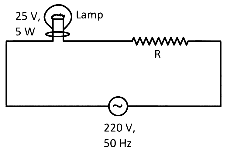
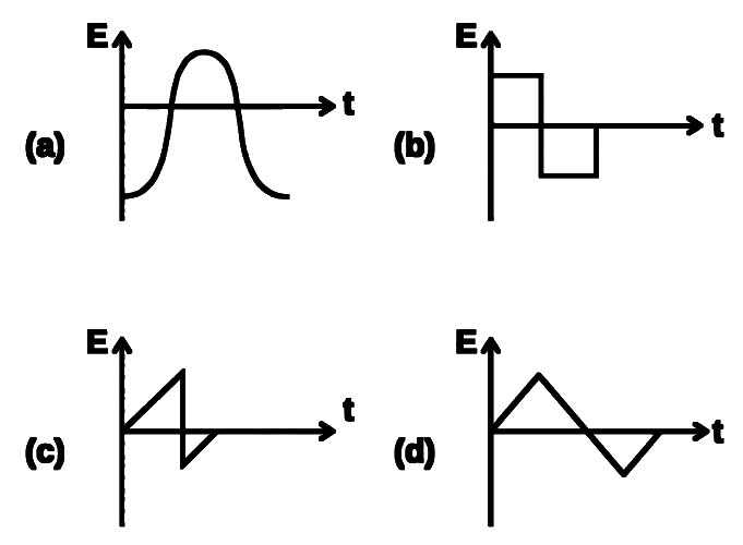
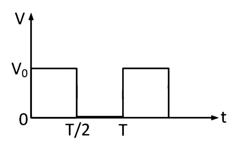
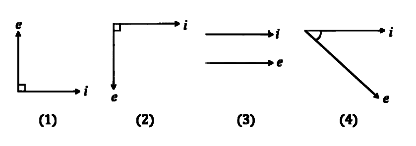
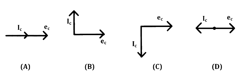
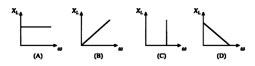
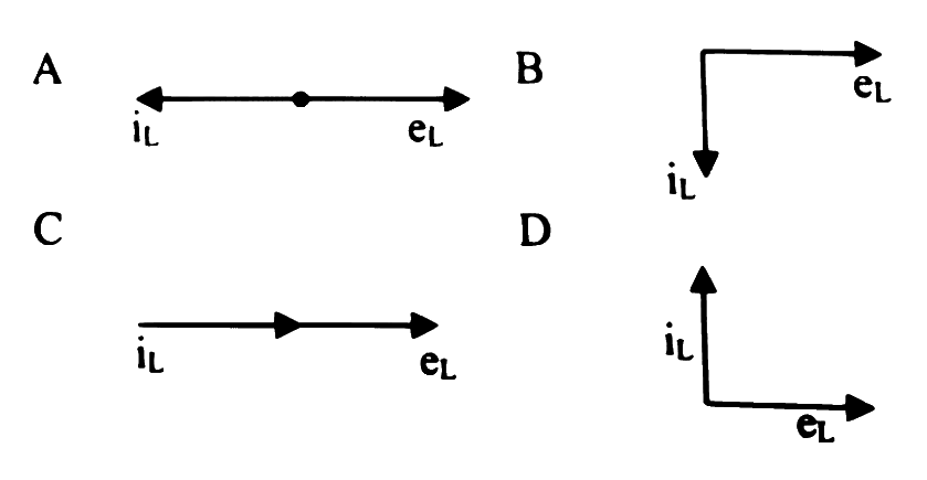
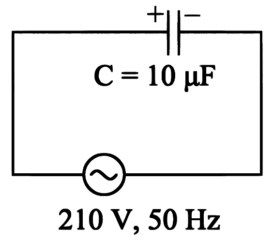
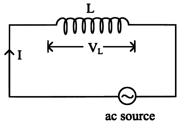
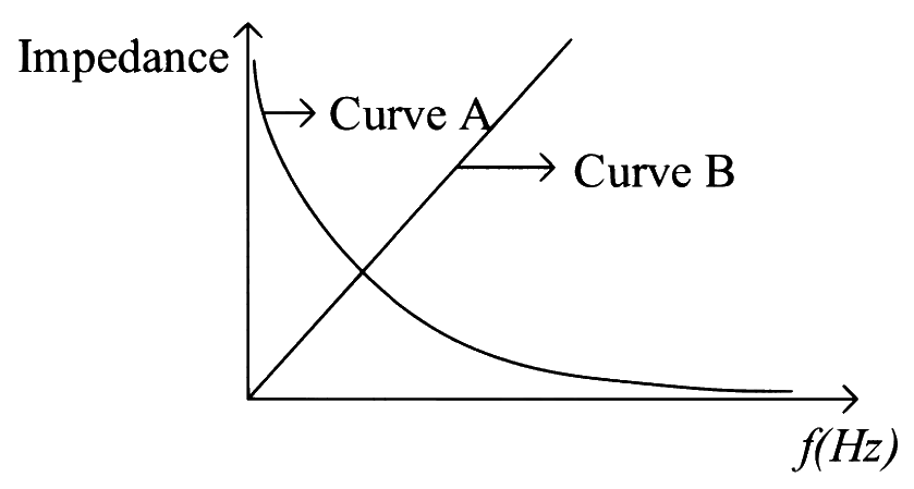
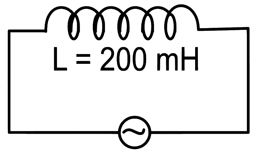
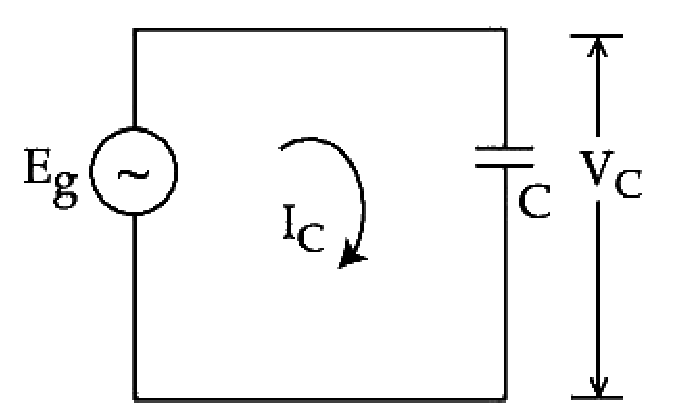
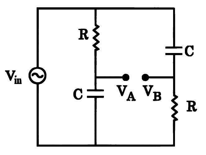
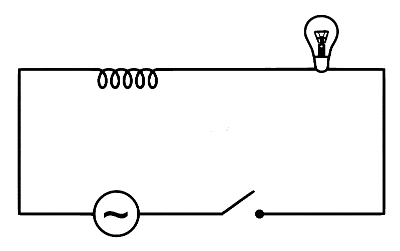
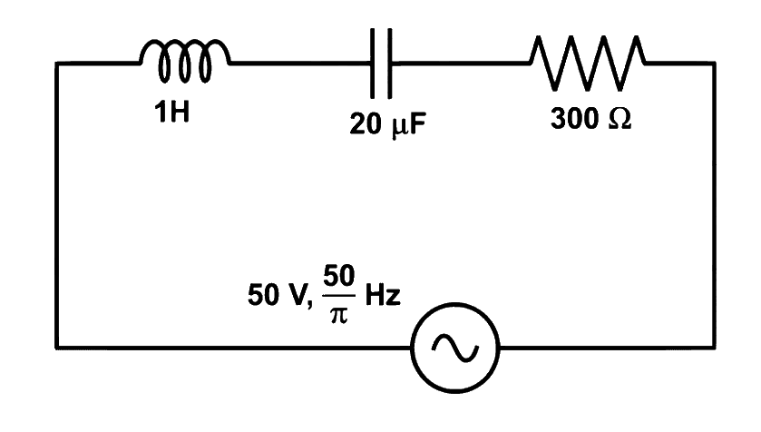
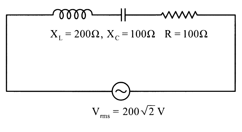
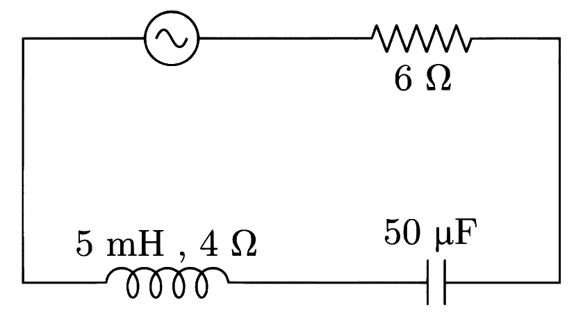
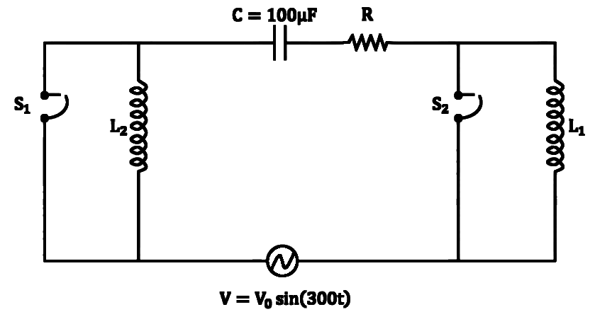
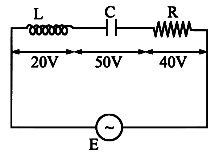
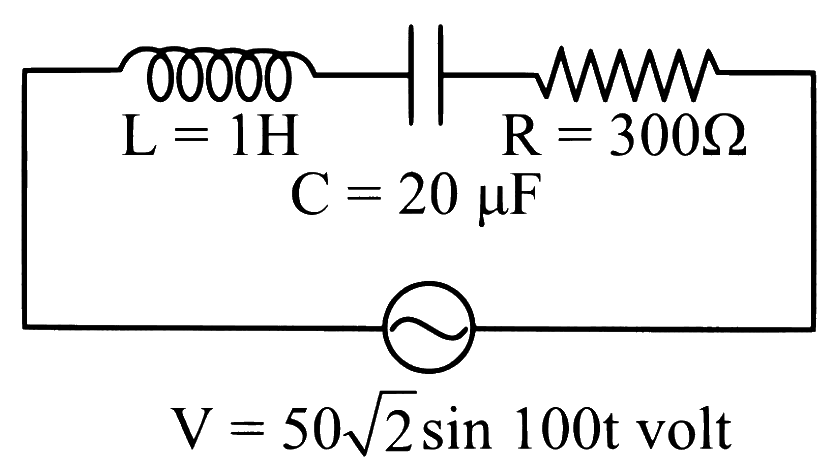
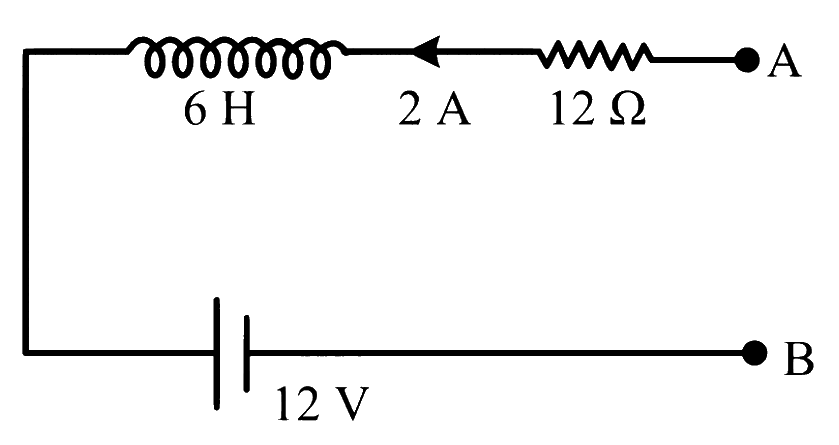
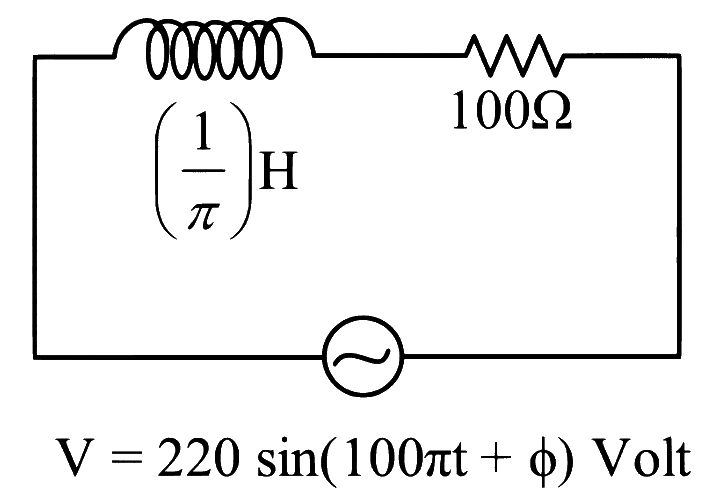
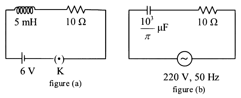
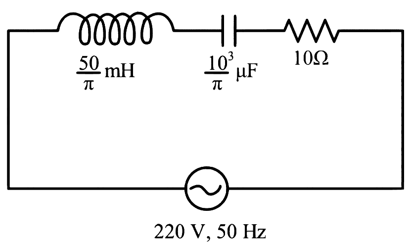
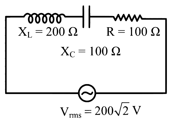
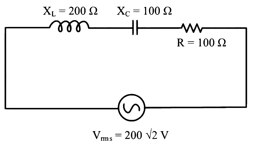
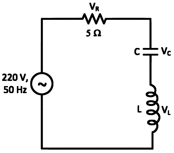
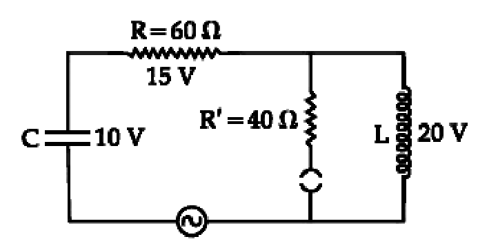
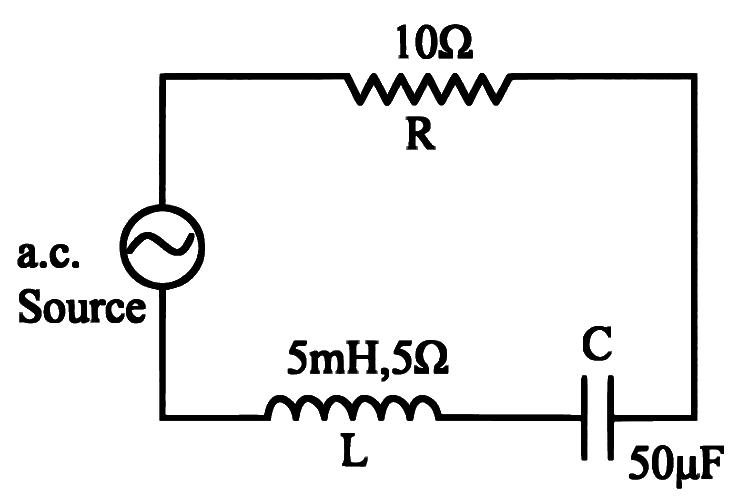
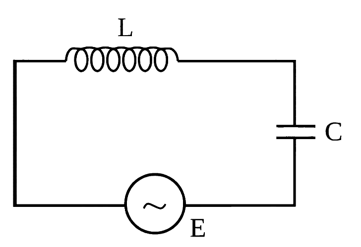
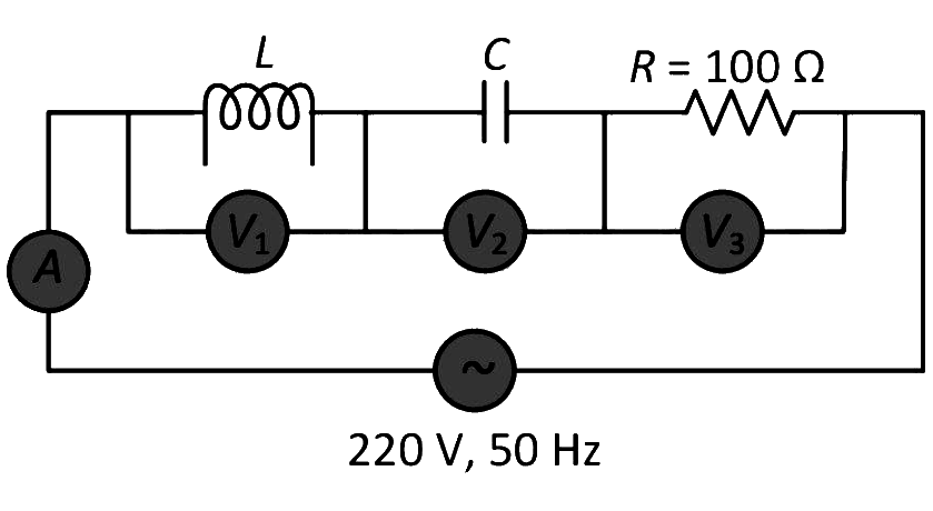
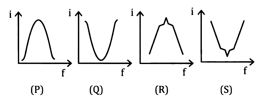
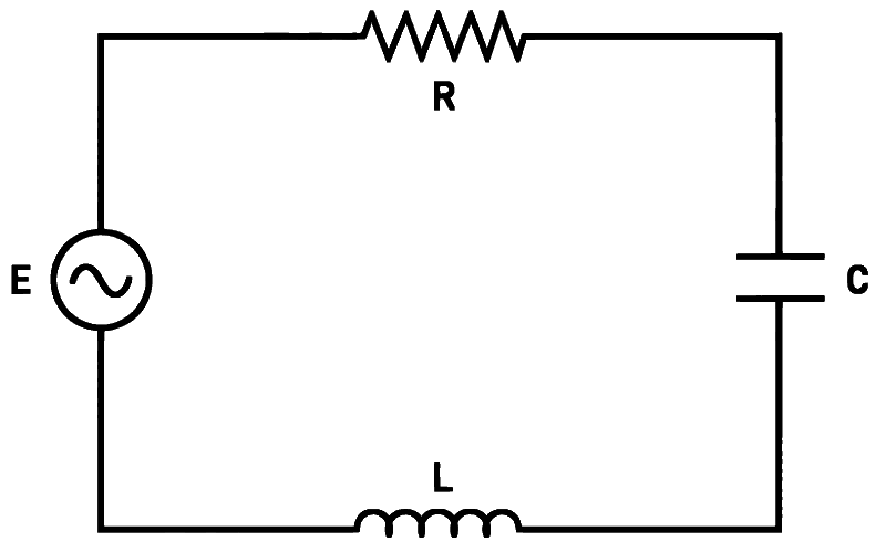
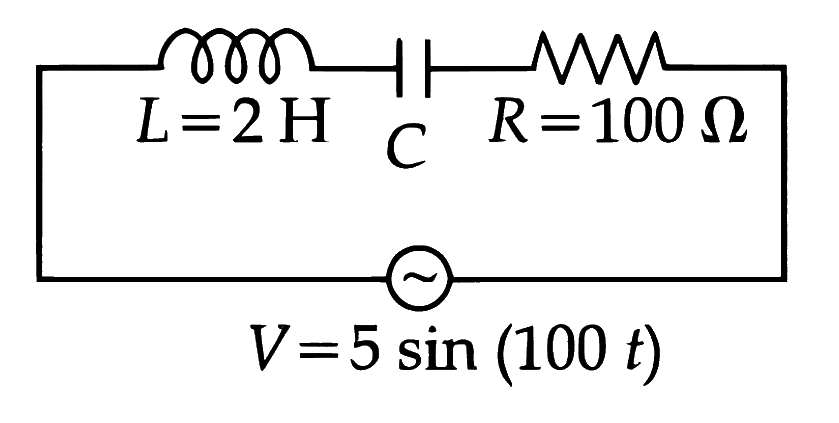
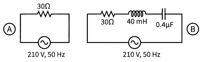
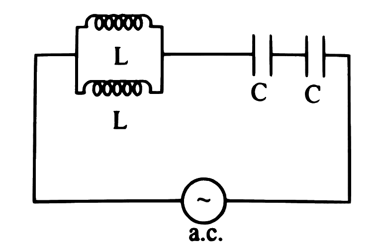
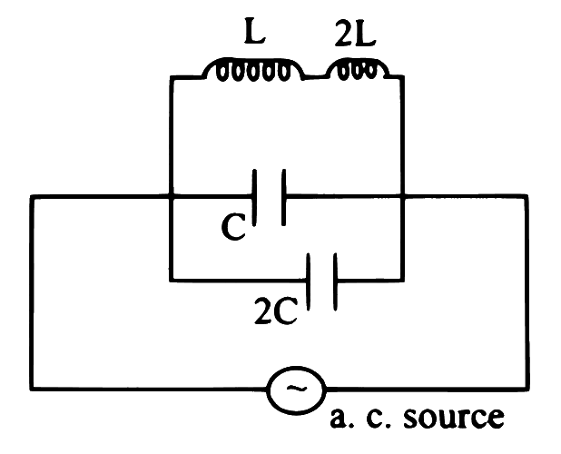
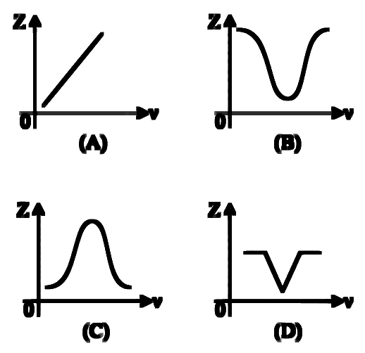
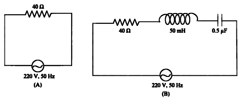
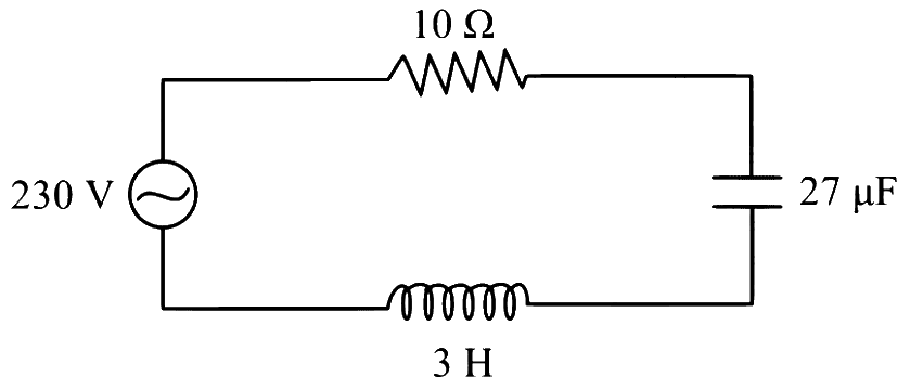
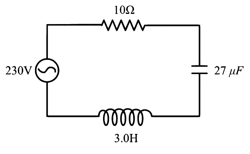
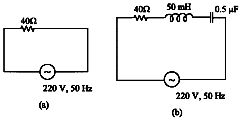
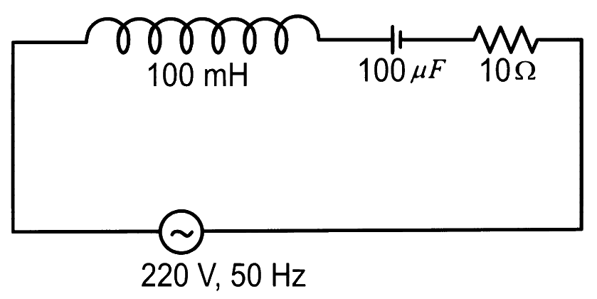
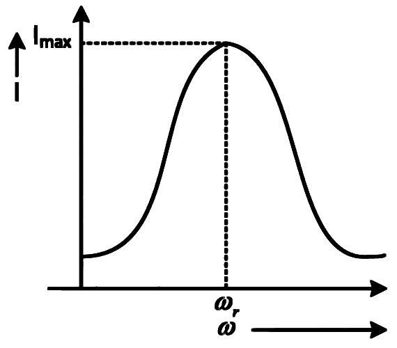 Choose the most appropriate answer from the options given below: