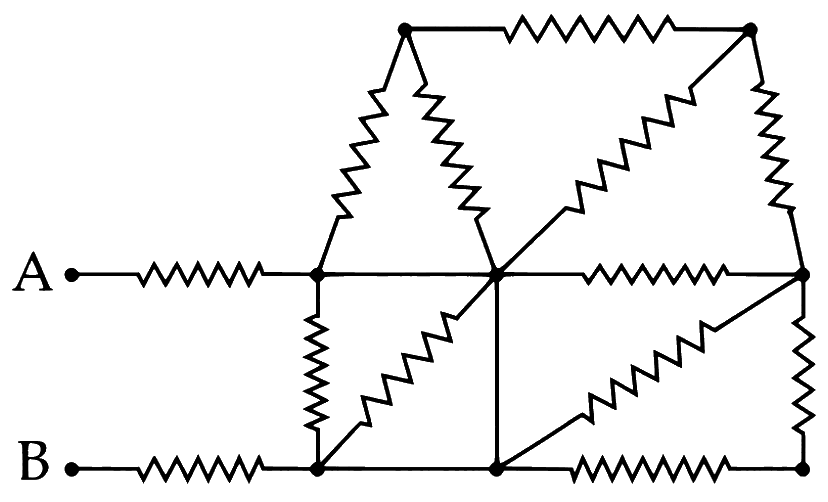
Electric Current, Drift Velocity & Current Density · Mobility & current density
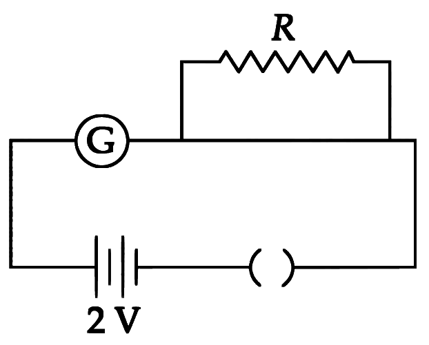
A cylindrical conductor of length 2 m and area of cross-section 0.2 mm2 carries an electric current of 1.6 A when its ends are connected to a 2 V battery. Mobility of electrons in the conductor is α×10−3 m2/V s. The value of α is:
(electron concentration =5×1028 /m3 and electron charge =1.6×10⁻¹⁹ C)
Numerical answer type. Work it out, then open the answer.
Electric Current, Drift Velocity & Current Density · Current & charge flow
The electric current through a wire varies with time as I=I0+βt, where I0=20 A and β=3 A/s. The amount of electric charge crossed through a section of the wire in 20 s is:
Electric Current, Drift Velocity & Current Density · Current & charge flow
The current in a conductor is expressed as I=3t2+4t3, where I is in Ampere and t is in second. The amount of electric charge that flows through a section of the conductor during t=1 s to t=2 s is __________ C.
Numerical answer type. Work it out, then open the answer.
Electric Current, Drift Velocity & Current Density · Drift velocity & relaxation time
A uniform wire of diameter d carries a current of 100 mA when the mean drift velocity of electrons in the wire is v. For a wire of diameter 2d of the same material to carry a current of 200 mA, the mean drift velocity of electrons in the wire is
Electric Current, Drift Velocity & Current Density · Drift velocity & relaxation time
A copper wire of radius 1 mm contains 1022 free electrons per cubic metre. The drift velocity for free electrons when 10 A current flows through the wire will be (Given, charge on electron =1.6×10⁻¹⁹ C):
Electric Current, Drift Velocity & Current Density · Drift velocity & relaxation time
In a metallic conductor, under the effect of applied electric field, the free electrons of the conductor
Show answer and solution
Answer: (d)
Electrons carry negative charge, so the force −eE pushes them opposite to E, i.e. from lower to higher potential.
Between collisions they accelerate under this force, and collisions keep changing their direction, so the paths are curved, not straight lines at uniform velocity.
Electric Current, Drift Velocity & Current Density · Drift velocity & relaxation time
The number density of free electrons in copper is nearly 8×1028 m−3. A copper wire has its area of cross section =2×10⁻⁶ m2 and is carrying a current of 3.2 A. The drift speed of the electrons is ___________ ×10−6 m s−1
Numerical answer type. Work it out, then open the answer.
Electric Current, Drift Velocity & Current Density · Drift velocity & relaxation time
A current of 2 A flows through a wire of cross-sectional area 25.0 mm2. The number of free electrons in a cubic meter are 2.0×1028. The drift velocity of the electrons is __________ ×10−6 m s−1 (given, charge on electron =1.6×10⁻¹⁹ C ).
Numerical answer type. Work it out, then open the answer.
Electric Current, Drift Velocity & Current Density · Drift velocity & relaxation time
The drift velocity of electrons for a conductor connected in an electrical circuit is Vd. The conductor is now replaced by another conductor with same material and same length but double the area of cross section. The applied voltage remains same. The new drift velocity of electrons will be
Show answer and solution
Answer: (b)
vd=meEτ=mleVτ
Same material (τ), same V and same l, so vd does not depend on the area.
Electric Current, Drift Velocity & Current Density · Drift velocity & relaxation time
(A) The drift velocity of electrons decreases with the increase in the temperature of conductor. (B) The drift velocity is inversely proportional to the area of cross-section of given conductor. (C) The drift velocity does not depend on the applied potential difference to the conductor. (D) The drift velocity of electron is inversely proportional to the length of the conductor. (E) The drift velocity increases with the increase in the temperature of conductor. Choose the correct answer from the options given below:
Show answer and solution
Answer: (b)
vd=meEτ=mleVτ
(A) True: τ falls as temperature rises, so vd decreases. (E) is therefore false.
(B) False: for a given V, vd does not depend on area. (C) False: vd∝V.
Electric Current, Drift Velocity & Current Density · Mobility & current density
A copper wire of length 10 m and radius (π10−2) m has electrical resistance of 10 Ω. The current density in the wire for an electric field strength of 10 (V/m) is
Electric Current, Drift Velocity & Current Density · Drift velocity & relaxation time
A 1 m long copper wire carries a current of 1 A. If the cross section of the wire is 2.0 mm2 and the resistivity of copper is 1.7×10⁻⁸Ω m, the force experienced by moving electron in the wire is ____________ ×10−23 N.
(charge on electron =1.6×10⁻¹⁹ C)
Numerical answer type. Work it out, then open the answer.
Electric Current, Drift Velocity & Current Density · Mobility & current density
The current density in a cylindrical wire of radius r = 4.0 mm is 1.0 × 10⁶ A/m2. The current through the outer portion of the wire between radial distances 2r and r is xπ A; where x is __________.
Numerical answer type. Work it out, then open the answer.
Electric Current, Drift Velocity & Current Density · Mobility & current density
The current density in a cylindrical wire of radius 4 mm is 4 × 10⁶ Am−2. The current through the outer portion of the wire between radial distances 2R and R is ____________ π A.
Numerical answer type. Work it out, then open the answer.
Electric Current, Drift Velocity & Current Density · Drift velocity & relaxation time
A current of 10A exists in a wire of cross-sectional area of 5 mm2 with a drift velocity of 2 × 10⁻³ ms−1. The number of free electrons in each cubic meter of the wire is ___________.
Electric Current, Drift Velocity & Current Density · Drift velocity & relaxation time
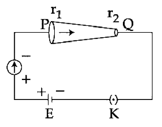
In the given figure, a battery of emf E is connected across a conductor PQ of length 'l' and different area of cross-sections having radii r1 and r2 (r2 < r1).
Choose the correct option as one moves from P to Q:
Show answer and solution
Answer: (a)
The current I is the same at every section of PQ (series path), so (c) is wrong.
From P to Q the area falls (r2<r1), so J=AI increases.
vd=neJ increases and E=ρJ also increases, so (b) is wrong.
Electric Current, Drift Velocity & Current Density · Drift velocity & relaxation time
A conducting wire of length 'l', area of cross-section A and electric resistivity ρ is connected between the terminals of a battery. A potential difference V is developed between its ends, causing an electric current.
If the length of the wire of the same material is doubled and the area of cross-section is halved, the resultant current would be:
Electric Current, Drift Velocity & Current Density · Mobility & current density
A current of 5 A is passing through a non-linear magnesium wire of cross-section 0.04 m2. At every point the direction of current density is at an angle of 60∘ with the unit vector of area of cross- section. The magnitude of electric field at every point of the conductor is:
Electric Current, Drift Velocity & Current Density · Mobility & current density
A cylindrical wire of radius 0.5 mm and conductivity 5 × 10⁷ S/m is subjected to an electric field of 10 mV/m. The expected value of current in the wire will be x3π mA. The value of x is _________.
Numerical answer type. Work it out, then open the answer.
Electric Current, Drift Velocity & Current Density · Drift velocity & relaxation time
Drift speed of electrons, when 1.5 A of current flows in a copper wire of cross section 5 mm2, is v. If the electron density in copper is 9 × 1028/m3 the value of v. in mm/s is close to (Take charge of electron to be = 1.6 × 10⁻¹⁹C)
Electric Current, Drift Velocity & Current Density · Drift velocity & relaxation time
In a conductor, if the number of conduction electrons per unit volume is 8.5 × 1028 m–3 and mean free time is 25ƒs (femto second), it's approximate resistivity is :-
Electric Current, Drift Velocity & Current Density · Mobility & current density
A current of 5 A passes through a copper conductor (resistivity = 1.7 × 10⁻⁸ Ωm) of radius of cross- section 5 mm. Find the mobility of the charges if their drift velocity is 1.1 × 10⁻³ m/s.
Electric Current, Drift Velocity & Current Density · Drift velocity & relaxation time
A copper rod of cross-sectional area A carries a uniform current I through it. At temperature T, if the volume charge density of the rod is ρ, how long will the charges take to travel a distance d?
Show answer and solution
Answer: (c)
Here ρ is the charge per unit volume, so I=ρAv and v=ρAI
Electric Current, Drift Velocity & Current Density · Drift velocity & relaxation time
Across a metallic conductor of non-uniform cross section a constant potential difference is applied. The quantity which remains constant along the conductor is
Show answer and solution
Answer: (d)
The conductor is a single series path, so the same charge passes every section per second: current I is constant.
J=I/A, vd=I/(neA) and E=ρJ all change with area A.
Electric Current, Drift Velocity & Current Density · Drift velocity & relaxation time
When 5 V potential difference is applied across a wire of length 0.1 m, the drift speed of electrons is 2.5×10⁻⁴ m s−1. If the electron density in the wire is 8×1028 m−3, the resistivity of the material is close to:
Electric Current, Drift Velocity & Current Density · Drift velocity & relaxation time
−8
The mean free path of electrons in a metal is 4 × 10 m. The electric field which can give on an average 2 eV energy to an electron in the metal will be in units V/m
Ohm's Law, Resistivity & Temperature · Resistivity: R = ρl/A
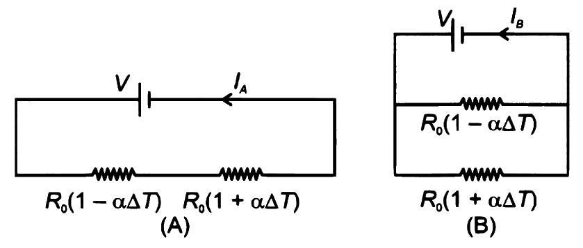
Consider two circuits, (A) and (B), each having two resistors. One of them has a positive temperature coefficient of resistance, +α, while the other one has a negative temperature coefficient, −α, as shown in the figure. The currents through these circuits are denoted by IA and IB. At initial temperature, the resistance of the two resistors is R0. As the temperature is increased, the correct option that describes the variation of current in these circuits is:
Show answer and solution
Answer: (b)
Circuit A (series): RA=R0(1−αΔT)+R0(1+αΔT)=2R0, independent of temperature.
So IA=V/2R0 stays constant.
Circuit B (parallel): RB=2R0R02(1−α2ΔT2)=2R0(1−α2ΔT2), which decreases as ΔT rises.
Ohm's Law, Resistivity & Temperature · Temperature dependence of resistance
At room temperature (27∘C), the resistance of a heating element is 50Ω. The temperature coefficient of the material is 2.4×10⁻⁴∘C−1. The temperature of the element, when its resistance is 62Ω, is __________ ∘C.
Numerical answer type. Work it out, then open the answer.
Ohm's Law, Resistivity & Temperature · Ohm's law & V–I graphs
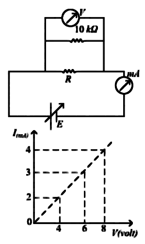
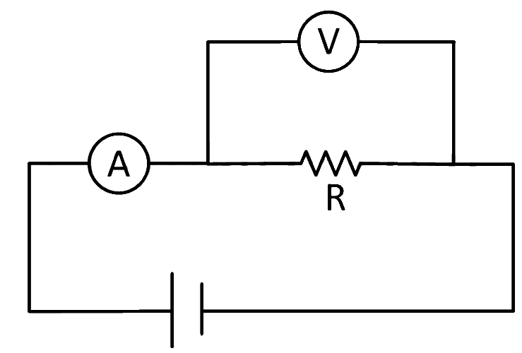
To determine the resistance (R) of a wire, a circuit is designed below. The V-I characteristic curve for this circuit is plotted for the voltmeter and the ammeter readings as shown in figure. The value of R is _________ Ω.
Numerical answer type. Work it out, then open the answer.
Show answer and solution
Answer: 2500
The voltmeter reads the voltage across R in parallel with 10 kΩ; the mA meter reads the total current.
Ohm's Law, Resistivity & Temperature · Resistivity: R = ρl/A
Two wires A and B are made up of the same material and have the same mass. Wire A has radius of 2.0 mm and wire B has radius of 4.0 mm. The resistance of wire B is 2Ω. The resistance of wire A is ________ Ω.
Numerical answer type. Work it out, then open the answer.
Show answer and solution
Answer: 32
Same material and mass, so same volume V=lA; then R=ρl/A=ρV/A2∝1/r4.
Ohm's Law, Resistivity & Temperature · Stretching & reshaping a wire
A wire of resistance R and radius r is stretched till its radius became r/2. If new resistance of the stretched wire is xR, then value of x is ________.
Numerical answer type. Work it out, then open the answer.
Ohm's Law, Resistivity & Temperature · Temperature dependence of resistance
Two conductors have the same resistances at 0∘C but their temperature coefficients of resistance are α1 and α2. The respective temperature coefficients for their series and parallel combinations are:
Show answer and solution
Answer: (b)
Series: Rs=R0(1+α1t)+R0(1+α2t)=2R0(1+2α1+α2t), so αs=2α1+α2.
Ohm's Law, Resistivity & Temperature · Temperature dependence of resistance
An electric toaster has resistance of 60Ω at room temperature (27∘C). The toaster is connected to a 220 V supply. If the current flowing through it reaches 2.75 A, the temperature attained by toaster is around: ( if α=2×10⁻⁴/∘C)
Ohm's Law, Resistivity & Temperature · Resistivity: R = ρl/A
A certain wire A has resistance 81Ω. The resistance of another wire B of same material and equal length but of diameter thrice the diameter of A will be:
Ohm's Law, Resistivity & Temperature · Resistivity: R = ρl/A
A rectangular parallelopiped is measured as 1 cm×1 cm×100 cm. If its specific resistance is 3×10⁻⁷Ω m, then the resistance between its two opposite rectangular faces will be ___________ ×10−7Ω.
Numerical answer type. Work it out, then open the answer.
Show answer and solution
Answer: 3
The rectangular faces are 1 cm×100 cm; the distance between opposite rectangular faces is 1 cm.
Ohm's Law, Resistivity & Temperature · Resistivity: R = ρl/A
A uniform metallic wire carries a current 2 A, when 3.4 V battery is connected across it. The mass of uniform metallic wire is 8.92 × 10⁻³ kg, density is 8.92 × 10³ kg/m3 and resistivity is 1.7 × 10⁻⁸Ω⋅m. The length of wire is:
Ohm's Law, Resistivity & Temperature · Resistivity: R = ρl/A
The current flowing through a conductor connected across a source is 2 A and 1.2 A at 0∘C and 100∘C respectively. The current flowing through the conductor at 50∘C will be ___________ ×102 mA.
Numerical answer type. Work it out, then open the answer.
Ohm's Law, Resistivity & Temperature · Resistivity: R = ρl/A
A hollow cylindrical conductor has length of 3.14 m, while its inner and outer diameters are 4 mm and 8 mm respectively. The resistance of the conductor is n×10−3Ω. If the resistivity of the material is 2.4×10⁻⁸Ω m, the value of n is ___________.
Numerical answer type. Work it out, then open the answer.
Ohm's Law, Resistivity & Temperature · Stretching & reshaping a wire
The length of a metallic wire is increased by 20% and its area of cross section is reduced by 4%. The percentage change in resistance of the metallic wire is __________.
Numerical answer type. Work it out, then open the answer.
Ohm's Law, Resistivity & Temperature · Stretching & reshaping a wire
A wire of resistance R1 is drawn out so that its length is increased by twice of its original length. The ratio of new resistance to original resistance is:
Show answer and solution
Answer: (a)
Length increased by twice its original length: l′=l+2l=3l.
Ohm's Law, Resistivity & Temperature · Stretching & reshaping a wire
The length of a given cylindrical wire is increased to double of its original length. The percentage increase in the resistance of the wire will be ____________ %.
Numerical answer type. Work it out, then open the answer.
Ohm's Law, Resistivity & Temperature · Temperature dependence of resistance
Given below are two statements: one is labelled as Assertion A and the other is labelled as Reason R.
Assertion A: Alloys such as constantan and manganin are used in making standard resistance coils. Reason R: Constantan and manganin have very small value of temperature coefficient of resistance. In the light of the above statements, choose the correct answer from the options given below.
Show answer and solution
Answer: (a)
Assertion: constantan and manganin are used for standard resistance coils. True.
Reason: they have a very small temperature coefficient of resistance, so their resistance stays nearly constant. True.
This small α is exactly why they are chosen, so R explains A.
Ohm's Law, Resistivity & Temperature · Temperature dependence of resistance
Resistance of the wire is measured as 2 Ω and 3 Ω at 10∘C and 30∘C respectively. Temperature co- efficient of resistance of the material of the wire is:
Ohm's Law, Resistivity & Temperature · Resistivity: R = ρl/A
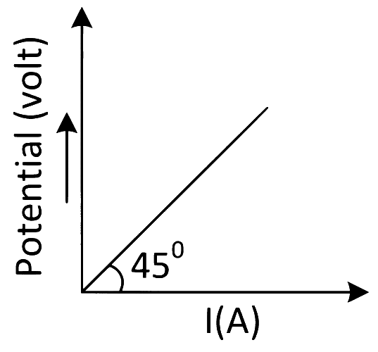
The variation of applied potential and current flowing through a given wire is shown in figure. The length of wire is 31.4 cm. The diameter of wire is measured as 2.4 cm. The resistivity of the given wire is measured as x × 10−3 Ω cm. The value of x is ____________. [Take π = 3.14]
Numerical answer type. Work it out, then open the answer.
Ohm's Law, Resistivity & Temperature · Stretching & reshaping a wire
A 1 m long wire is broken into two unequal parts X and Y. The X part of the wire is streched into another wire W. Length of W is twice the length of X and the resistance of W is twice that of Y. Find the ratio of length of X and Y.
Show answer and solution
Answer: (b)
Let lengths be x (X) and y (Y); same wire, so R=kl before stretching: RX=kx, RY=ky.
Stretching X to twice its length (volume constant) multiplies resistance by 22: RW=4kx.
Ohm's Law, Resistivity & Temperature · Resistivity: R = ρl/A
Two solid conductors are made up of same material, have same length and same resistance. One of them has a circular cross section of area A1 and the other one has a square cross section of area A2. The ratio A1/A2 is
Show answer and solution
Answer: (c)
R=Aρl⇒A=Rρl
Same ρ, same l and same R, so the areas are equal whatever the shape.
Ohm's Law, Resistivity & Temperature · Resistivity: R = ρl/A
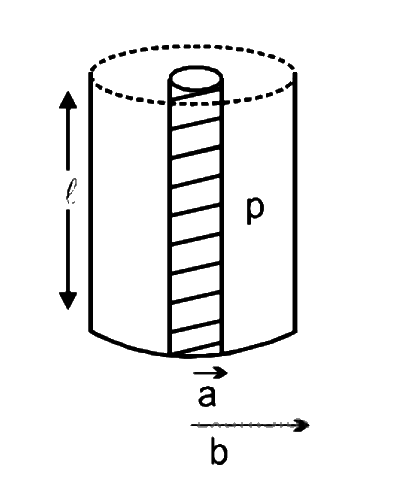
Model a torch battery of length l to be made up of a thin cylindrical bar of radius ‘a’ and a concentric thin cylindrical shell of radius ‘b’ filled in between with an electrolyte of resistivity ρ (see figure). If the battery is connected to a resistance of value R, the maximum Joule heating in R will take place for:
Show answer and solution
Answer: (c)
Internal resistance: current flows radially through shells of area 2πrl, so rint=∫ab2πrlρdr=2πlρlnab.
Power in R is maximum when R=rint (maximum power transfer).
Ohm's Law, Resistivity & Temperature · Temperature dependence of resistance
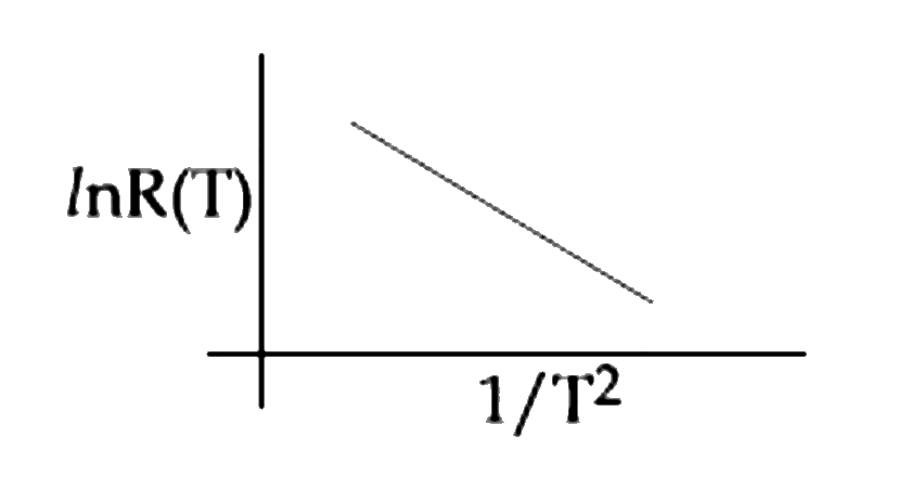
In an experiment, the resistance of a material is plotted as a function of temperature (in some range). As shown in the figure, it is a straight line. One may conclude that:
Show answer and solution
Answer: (d)
Graph: lnR vs 1/T2 is a straight line with negative slope.
Ohm's Law, Resistivity & Temperature · Resistivity: R = ρl/A
Space between two concentric conducting spheres of radii a and b (b > a) is filled with a medium of resistivity ρ. The resistance between the two spheres will be:
Show answer and solution
Answer: (d)
Current flows radially through spherical shells of area 4πr2: dR=4πr2ρdr.
Ohm's Law, Resistivity & Temperature · Temperature dependence of resistance
A heating element has a resistance of 100 Ω at room temperature. When it is connected to a supply of 220 V, a steady current of 2 A passes in it and temperature is 500oC more than room temperature. What is the temperature coefficient of resistance of the heating element?
Ohm's Law, Resistivity & Temperature · Temperature dependence of resistance
The resistance of an electrical toaster has a temperature dependence given by R(T) = R0 [1 + α(T − T0)] in its range of operation. At T0 = 300 K, R = 100 Ω and at T = 500 K, R = 120 Ω. The toaster is connected to a voltage source at 200 V and its temperature is raised at a constant rate from 300 to 500 K in 30 s. The total work done in raising the temperature is:
Ohm's Law, Resistivity & Temperature · Ohm's law & V–I graphs
Suppose the drift velocity vd in a material varied with the applied electric field E as vd ∝E. Then V - I graph for a wire made of such a material is best given by:
Show answer and solution
Answer: (c)
I=neAvd, so I∝vd∝E.
E=V/l⇒I∝V⇒V∝I2
The V–I graph is a parabola through the origin, bending upward.
Ohm's Law, Resistivity & Temperature · Temperature dependence of resistance
Two conductors have the same resistance at 0∘C but their temperature coefficients of resistance are α1 and α2. The respective temperature coefficients of their series and parallel combinations are nearly
Ohm's Law, Resistivity & Temperature · Temperature dependence of resistance
Statement - 1: The temperature dependence of resistance is usually given as R=R0(1+αΔt). The resistance of wire changes from 100Ω to 150Ω when its temperature is increased from 27∘C to 227∘C. This implies that α=2.5×10⁻³/C.
Statement - 2: R=R0(1+αΔt) is valid only when the change in the temperature ΔT is small and ΔR=(R−R0)≪R0.
Show answer and solution
Answer: (c)
Statement 2: the linear law R=R0(1+αΔt) is an approximation valid only for small changes, ΔR≪R0. True.
Statement 1: here ΔR=50Ω is half of R0, not small, so the linear formula cannot be applied to get α reliably. False.
Ohm's Law, Resistivity & Temperature · Resistivity: R = ρl/A
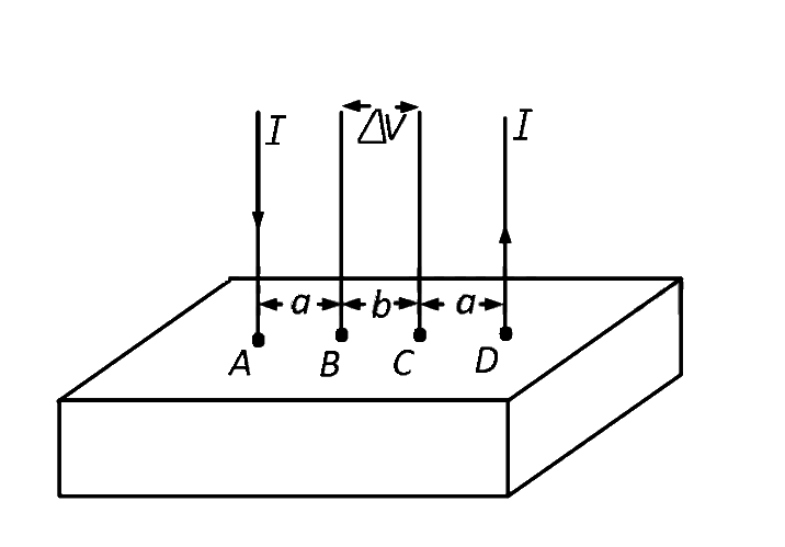
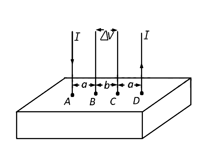
Consider a block of conducting material of resistivity ’ρ’ shown in the figure. Current ’I’ enters at ’A’ and leaves from ’D’. We apply superposition principle to find voltage ’ΔV’ developed between ’B’ and ’C’. The calculation is done in the following steps:
(i) Take current ’I’ entering from ’A’ and assume it to spread over a hemispherical surface in the block.
(ii) Calculate field E(r) at distance ’r’ from A by using Ohm's law E=ρj, where j is the current per unit area at ’r’.
(iii) From the ’r’ dependence of E(r), obtain the potential V(r) at r.
(iv) Repeat (i), (ii) and (iii) for current ’I’ leaving ’D’ and superpose results for ’A’ and ’D’.
ΔV measured between B and C is
Show answer and solution
Answer: (a)
Current I at A spreads over a hemisphere: j=2πr2I, E=ρj, so V(r)=2πrρI.
Due to A: VB−VC=2πρI(a1−a+b1).
Due to D (current leaving, V=−2πrρI; B is at a+b, C at a from D): VB−VC=2πρI(a1−a+b1).
Ohm's Law, Resistivity & Temperature · Resistivity: R = ρl/A
Consider a block of conducting material of resistivity ’ρ’ shown in the figure. Current ’I’ enters at ’A’ and leaves from ’D’. We apply superposition principle to find voltage ’ΔV’ developed between ’B’ and ’C’. The calculation is done in the following steps:
(i) Take current ’I’ entering from ’A’ and assume it to spread over a hemispherical surface in the block.
(ii) Calculate field E(r) at distance ’r’ from A by using Ohm's law E=ρj, where j is the current per unit area at ’r’.
(iii) From the ’r’ dependence of E(r), obtain the potential V(r) at r.
(iv) Repeat (i), (ii) and (iii) for current ’I’ leaving ’D’ and superpose results for ’A’ and ’D’.
For current entering at A, the electric field at a distance ’r’ from A is
Show answer and solution
Answer: (c)
Current from A spreads over a hemisphere of area 2πr2 (the block surface is flat).
Ohm's Law, Resistivity & Temperature · Resistivity: R = ρl/A
A material 'B' has twice the specific resistance of 'A'. A circular wire made of 'B' has twice the diameter of a wire made of 'A'. Then for the two wires to have the same resistance, the ratio ℓB/ℓA of their respective lengths must be
Ohm's Law, Resistivity & Temperature · Temperature dependence of resistance
The resistance of bulb filament is 100Ω at a temperature of 100∘C. If its temperature coefficient of resistance be 0.005 per ∘C, its resistance will become 200Ω at a temperature of
Ohm's Law, Resistivity & Temperature · Resistivity: R = ρl/A
A material ′B′ has twice the specific resistance of ′A′. A circular wire made of ′B′ has twice the diameter of a wire made of ′A′. Then for the two wires to have the same resistance, the ratio lB/lA of their respective lengths must be
Ohm's Law, Resistivity & Temperature · Stretching & reshaping a wire
The length of a given cylindrical wire is increased by 100%. Due to the consequent decrease in diameter the change in the resistance of the wire will be
Combination of Resistors · Wires bent into loops & polygons
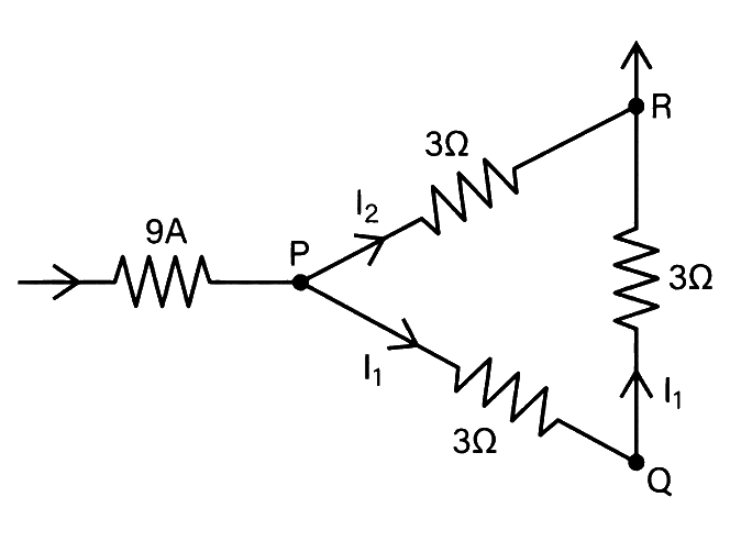
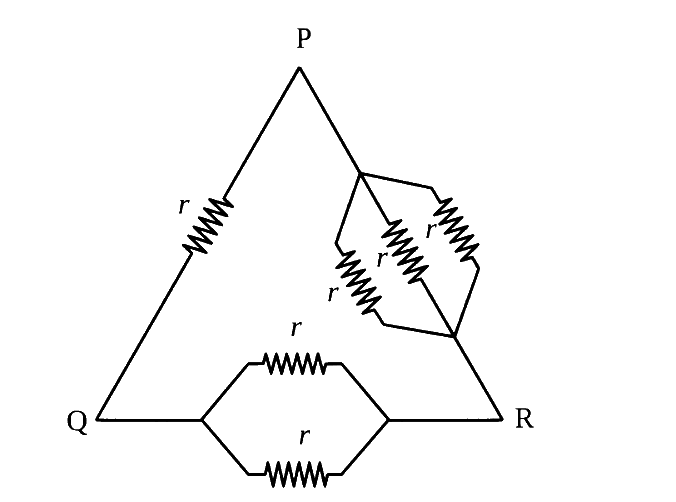
A current of 9A enters point P of an equilateral triangle PQR having three wires of 3Ω each and leaves by point R. The currents I1 and I2 are respectively
Show answer and solution
Answer: (b)
From P to R: direct path PR (3Ω) carries I2; path PQR (6Ω) carries I1.
Current divides inversely as resistance: I1=9×93=3 A, I2=9×96=6 A
Combination of Resistors · Wires bent into loops & polygons
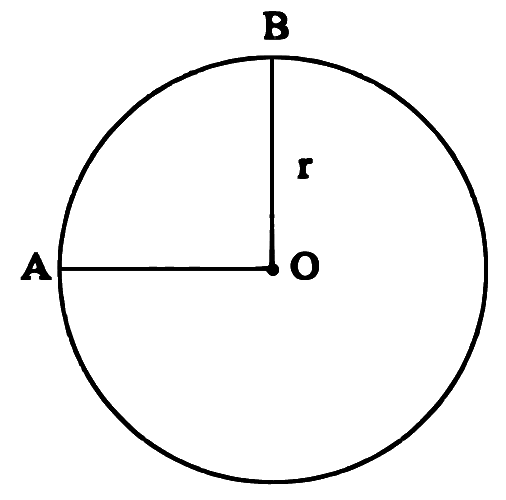
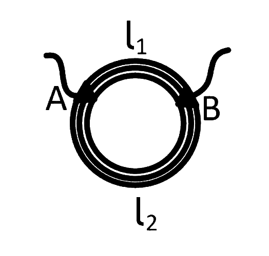
A wire of uniform resistance λΩ/m is bent into a circle of radius r and another piece of wire with length 2r is connected between points A and B(AOB) as shown in figure. The equivalent resistance between points A and B is ΩΩ.
Show answer and solution
Answer: (b)
A and B are 90∘ apart, so three paths join A and B in parallel.
Minor arc: 2πrλ; major arc: 23πrλ; straight wire AOB: 2rλ.
Combination of Resistors · Networks, symmetry & infinite ladders
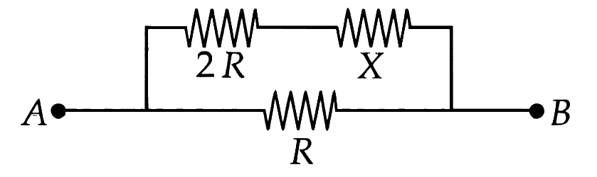
Two known resistances of RΩ and 2RΩ and one unknown resistance XΩ are connected in a circuit as shown in the figure. If the equivalent resistance between points A and B in the circuit is XΩ, then the value of X is __________ Ω.
Combination of Resistors · Wires bent into loops & polygons
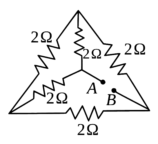
A regular hexagon is formed by six wires each of resistance rΩ and the corners are joined to the centre by wires of same resistance. If the current enters at one corner and leaves at the opposite corner, the equivalent resistance of the hexagon between the two opposite corners will be
Show answer and solution
Answer: (b)
Number corners 1 to 6, current in at 1, out at 4. Take V1=1, V4=0; by symmetry centre =21, V2=V6=x, V3=V5=1−x.
KCL at 2: (x−1)+(x−(1−x))+(x−21)=0⇒x=85
Current from 1 (in units of 1/r): 2(1−85)+21=45
Combination of Resistors · Series & parallel combinations
A wire of resistance R is cut into 8 equal pieces. From these pieces two equivalent resistances are made by adding four of these together in parallel. Then these two sets are added in series. The net effective resistance of the combination is:
Show answer and solution
Answer: (a)
Each piece has resistance R/8.
Four in parallel: 4R/8=32R.
Two such sets in series: 2×32R=16R. The answer is (a).
Combination of Resistors · Series & parallel combinations
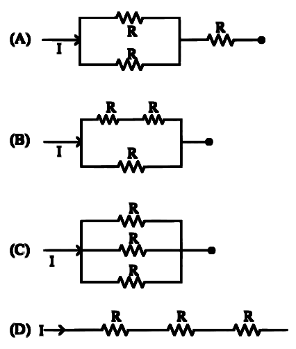
From the combination of resistors with resistances values R1=R2=R3=5Ω and R4=10Ω, which of the following combination is the best circuit to get an equivalent resistance of 6Ω?
Combination of Resistors · Wires bent into loops & polygons
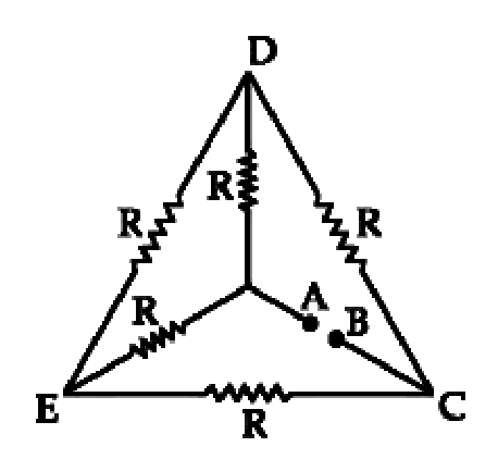
A wire of resistance R is bent into a triangular pyramid as shown in figure with each segment having same length. The resistance between points A and B is R/n. The value of n is:
Show answer and solution
Answer: (c)
The pyramid (tetrahedron) has 6 equal edges, each of resistance r=6R.
By symmetry the other two vertices are at the same potential, so the edge joining them carries no current.
Paths: direct r, plus two paths of 2r each, all in parallel: RAB1=r1+2r1+2r1=r2
Combination of Resistors · Wires bent into loops & polygons
A wire of length 25 m and cross-sectional area 5 mm2 having resistivity of 2×10⁻⁶Ω m is bent into a complete circle. The resistance between diametrically opposite points will be
Combination of Resistors · Wires bent into loops & polygons
A wire of resistance R is bent into an equilateral triangle and an identical wire is bent into a square. The ratio of resistance between the two end points of an edge of the triangle to that of the square is
Combination of Resistors · Networks, symmetry & infinite ladders
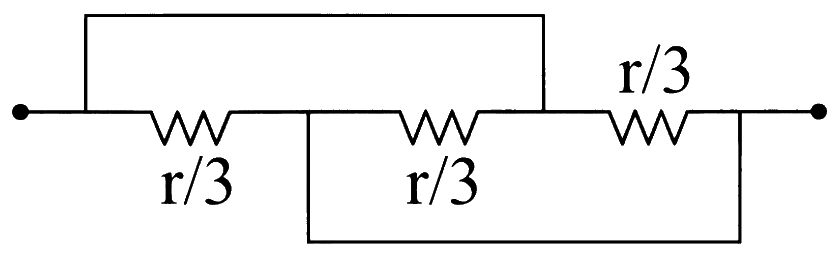
Find the equivalent resistance between two ends of the following circuit
Show answer and solution
Answer: (d)
The top wire joins the left end to the node between the 2nd and 3rd resistors; the bottom wire joins the node between the 1st and 2nd resistors to the right end.
So each of the three 3r resistors is connected directly between the two ends: all three are in parallel.
Combination of Resistors · Series & parallel combinations
A wire of length 'l' and resistance 100Ω is divided into 10 equal parts. The first 5 parts are connected in series while the next 5 parts are connected in parallel. The two combinations are again connected in series. The resistance of this final combination is:
Show answer and solution
Answer: (b)
Each part has 10100=10Ω.
5 parts in series: 50Ω. 5 parts in parallel: 510=2Ω.
Combination of Resistors · Series & parallel combinations
A wire of resistance 20Ω is divided into 10 equal parts, resulting pairs. A combination of two parts are connected in parallel and so on. Now resulting pairs of parallel combination are connected in series. The equivalent resistance of final combination is _________ Ω.
Numerical answer type. Work it out, then open the answer.
Combination of Resistors · Wires bent into loops & polygons
A uniform metal wire of length l has 10Ω resistance. Now this wire is stretched to a length 2l and then bent to form a perfect circle. The equivalent resistance across any arbitrary diameter of that circle is
Show answer and solution
Answer: (a)
Stretching to 2l (volume constant): R∝l2, so R′=4×10=40Ω.
Combination of Resistors · Networks, symmetry & infinite ladders
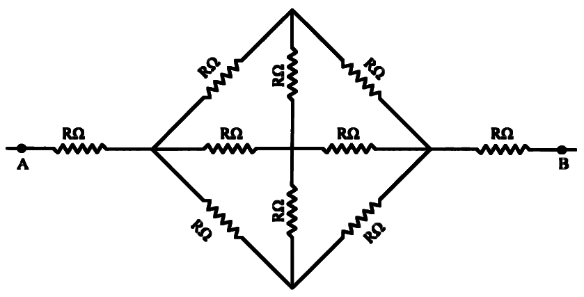
The effective resistance between A and B, if resistance of each resistor is R, will be:
Show answer and solution
Answer: (a)
Between the left and right corners of the diamond, the top, centre and bottom nodes are each joined by R to both corners, so all three are at the same potential.
The two vertical resistors therefore carry no current; three paths of 2R remain in parallel: 32R.
Combination of Resistors · Networks, symmetry & infinite ladders
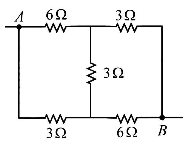
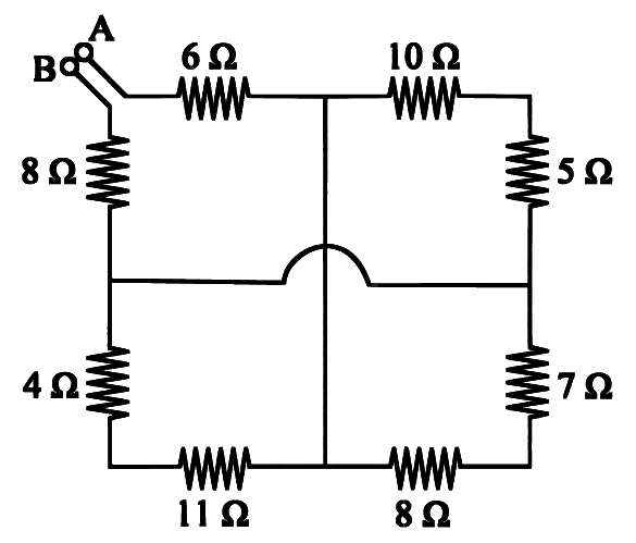
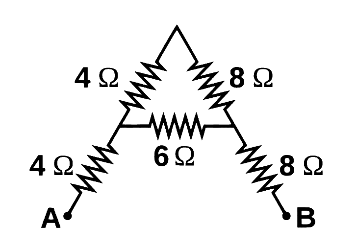
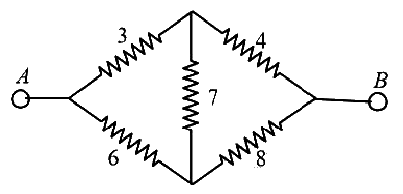
The equivalent resistance between A and B is:
Show answer and solution
Answer: (c)
A goes to the 6Ω, B to the 8Ω. The vertical middle wire makes the top-middle and bottom-middle points one node X; the horizontal middle wire (it jumps over the vertical one) makes the two side midpoints one node Y.
Between X and Y: 10+5=15, 7+8=15 and 11+4=15Ω, all in parallel =5Ω.
Combination of Resistors · Networks, symmetry & infinite ladders
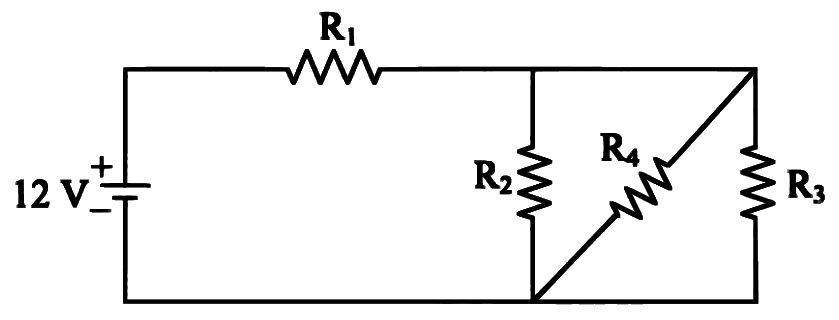
In the given figure R1=10Ω,R2=8Ω,R3=4Ω and R4=8Ω. Battery is ideal with emf 12 V. Equivalent resistance of the circuit and current supplied by battery are respectively:
Show answer and solution
Answer: (d)
R2, R4 and R3 all connect the same top node to the same bottom wire, so they are in parallel.
Combination of Resistors · Wires bent into loops & polygons
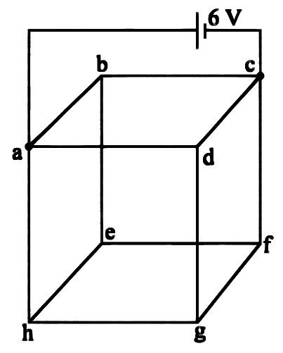
Twelve wires each having resistance 2Ω are joined to form a cube. A battery of 6 V emf is joined across point a and c. The voltage difference between e and f is ________ V.
Numerical answer type. Work it out, then open the answer.
Show answer and solution
Answer: 1
Battery across face diagonal a–c: take Va=6, Vc=0. By symmetry b, d, e, g are all at 3 V; let Vh=y and Vf=6−y.
KCL at h (neighbours a, e, g; equal resistances): (y−6)+(y−3)+(y−3)=0⇒y=4 V, so Vf=2 V.
Combination of Resistors · Series & parallel combinations
10 resistors, each of resistance R are connected in series to a battery of emf E and negligible internal resistance. Then those are connected in parallel to the same battery, the current is increased n times. The value of n is:
Combination of Resistors · Series & parallel combinations
10 resistors each of resistance 10 Ω can be connected in such as to get maximum and minimum equivalent resistance. The ratio of maximum and minimum equivalent resistance will be ___________.
Numerical answer type. Work it out, then open the answer.
Combination of Resistors · Networks, symmetry & infinite ladders
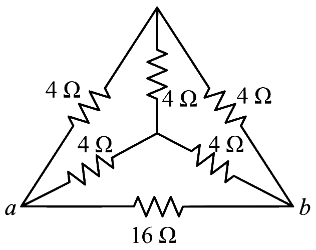
The equivalent resistance of the circuit shown below between points a and b is:
Show answer and solution
Answer: (c)
By symmetry the top vertex and the centre are both midway in potential between a and b (each joined by 4Ω to a and to b), so the vertical 4Ω carries no current.
Paths: a–top–b =8Ω, a–centre–b =8Ω, direct 16Ω, all in parallel.
Combination of Resistors · Networks, symmetry & infinite ladders
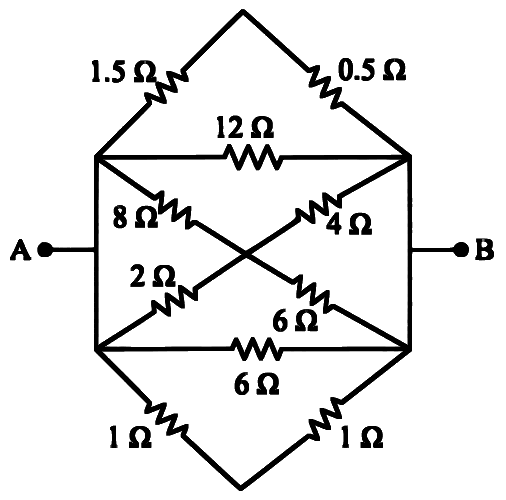
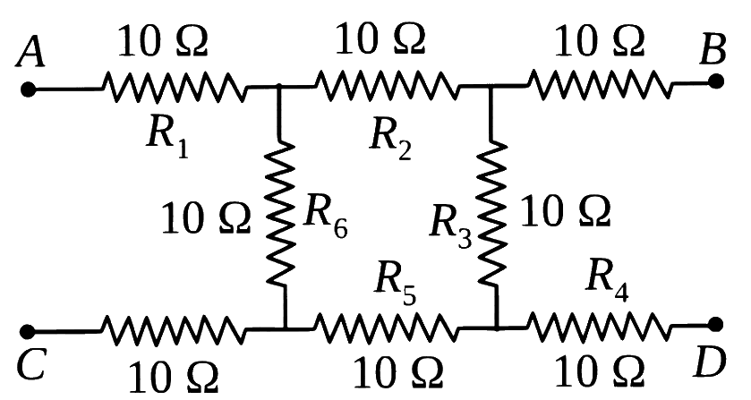
The equivalent resistance between A and B is _________.
Show answer and solution
Answer: (b)
The left vertical wire makes both left corners one node (A); the right vertical wire makes both right corners one node (B). Every branch then runs from A to B.
Branches: top 1.5+0.5=2, 12, diagonal 8+6=14, diagonal 2+4=6, 6, bottom 1+1=2Ω, all in parallel.
Combination of Resistors · Networks, symmetry & infinite ladders
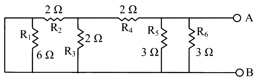
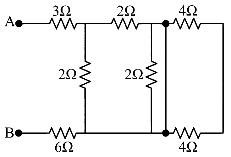
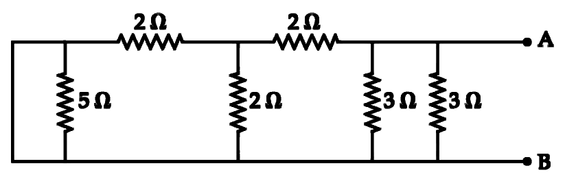
In the given circuit, the equivalent resistance between the terminal A and B is __________ Ω.
Numerical answer type. Work it out, then open the answer.
Show answer and solution
Answer: 10
The thick vertical wire joins the two right-hand dots, so the 4Ω loop is shorted and the node after the top 2Ω is at the bottom-rail potential; the second vertical 2Ω is shorted too.
From the node after 3Ω to the bottom rail: 2Ω (vertical) ∥2Ω (top) =1Ω.
Combination of Resistors · Series & parallel combinations
Two metallic wires of identical dimensions are connected in series. If σ1 and σ2 are the conductivities of these wires respectively, the effective conductivity of the combination is:
Show answer and solution
Answer: (b)
R=σAl. In series the combination has length 2l and area A.
Combination of Resistors · Series & parallel combinations
Given below are two statements:
Statement I: A uniform wire of resistance 80Ω is cut into four equal parts. These parts are now connected in parallel. The equivalent resistance of the combination will be 5Ω.
Statement II: Two resistances 2R and 3R are connected in parallel in an electric circuit. The value of thermal energy developed in 3R and 2R will be in the ratio 3:2.
In the light of the above statements, choose the most appropriate answer from the option given below
Show answer and solution
Answer: (c)
Statement I: each part is 20Ω; four in parallel give 420=5Ω. True.
Statement II: in parallel V is the same, so H=RV2t∝R1.
Combination of Resistors · Series & parallel combinations
An electric cable of copper has just one wire of radius 9 mm. Its resistance is 14 Ω. If this single copper wire of the cable is replaced by seven identical well insulated copper wires each of radius 3 mm connected in parallel, then the new resistance of the combination will be:
Combination of Resistors · Series & parallel combinations
Eight copper wire of length l and diameter d are joined in parallel to form a single composite conductor of resistance R. If a single copper wire of length 2l have the same resistance (R) then its diameter will be ____________ d.
Numerical answer type. Work it out, then open the answer.
Show answer and solution
Answer: 4
One wire: r0=πd24ρl; eight in parallel: R=8r0=2πd2ρl.
Combination of Resistors · Networks, symmetry & infinite ladders
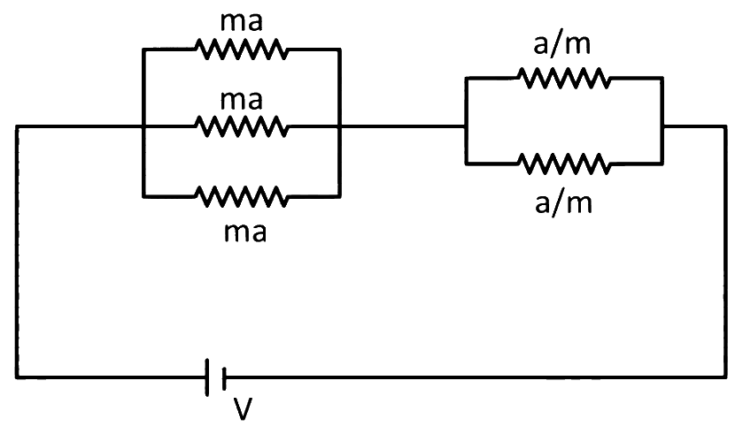
In the given circuit 'a' is an arbitrary constant. The value of m for which the equivalent circuit resistance is minimum, will be 2x. The value of x is __________.
Numerical answer type. Work it out, then open the answer.
Show answer and solution
Answer: 3
Three ma in parallel give 3ma; two ma in parallel give 2ma.
Combination of Resistors · Series & parallel combinations
The effective resistance of a parallel connection that consists of four wires of equal length, equal area of cross-section and same material is 0.25Ω. What will be the effective resistance if they are connected in series?
Combination of Resistors · Series & parallel combinations
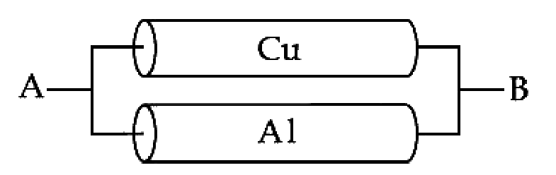
A Copper (Cu) rod of length 25 cm and cross-sectional area 3 mm2 is joined with a similar Aluminium (Al) rod as shown in figure. Find the resistance of the combination between the ends A and B.
(Take Resistivity of Copper = 1.7 × 10⁻⁸ Ωm and Resistivity of Aluminium = 2.6 × 10⁻⁸ Ωm)
Show answer and solution
Answer: (c)
The rods are in parallel. R=Aρl with l=0.25 m, A=3×10⁻⁶m2.
Combination of Resistors · Series & parallel combinations
Two wires of same length and thickness having specific resistances 6Ω cm and 3Ω cm respectively are connected in parallel. The effective resistivity is ρΩ cm. The value of ρ, to the nearest integer, is ____________.
Numerical answer type. Work it out, then open the answer.
Show answer and solution
Answer: 4
Same l and A, so R∝ρ. Parallel combination has length l and area 2A.
Combination of Resistors · Series & parallel combinations
The equivalent resistance of series combination of two resistors is 's'. When they are connected in parallel, the equivalent resistance is 'p'. If s = np, then the minimum value for n is ____________. (Round off to the Nearest Integer)
Numerical answer type. Work it out, then open the answer.
Show answer and solution
Answer: 4
n=ps=R1R2(R1+R2)2.
Since (R1+R2)2≥4R1R2, n≥4, with equality for R1=R2.
Combination of Resistors · Wires bent into loops & polygons
A square shaped wire with resistance of each side 3Ω is bent to form a complete circle. The resistance between two diametrically opposite points of the circle in unit of Ω will be ___________.
Numerical answer type. Work it out, then open the answer.
Show answer and solution
Answer: 3
Total resistance of the wire =4×3=12Ω.
Diametrically opposite points: two halves of 6Ω in parallel.
Combination of Resistors · Wires bent into loops & polygons
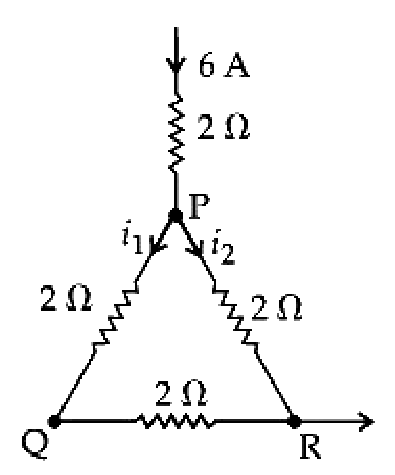
A current of 6A enters one corner P of an equilateral triangle PQR having 3 wires of resistance 2Ω each and leaves by the corner R. The currents i1 in ampere is _________.
Numerical answer type. Work it out, then open the answer.
Show answer and solution
Answer: 2
From P to R: path PQR (2+2=4Ω) carries i1; direct PR (2Ω) carries i2.
Current divides inversely as resistance: i1=6×4+22=2 A
Combination of Resistors · Networks, symmetry & infinite ladders
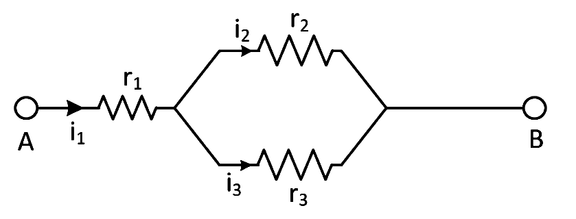
Three resistors having resistances r1, r2 and r3 are connected as shown in the given circuit. The ratio i1i3 of currents in terms of resistances used in the circuit is:
Show answer and solution
Answer: (c)
i1 through r1 divides between r2 and r3 in parallel.
Combination of Resistors · Networks, symmetry & infinite ladders
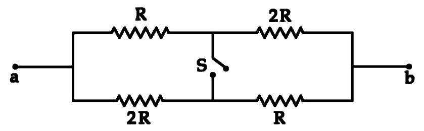
The ratio of the equivalent resistance of the network (shown in figure) between the points a and b when switch is open and switch is closed is x: 8. The value of x is ___________.
Numerical answer type. Work it out, then open the answer.
Show answer and solution
Answer: 9
Switch open: two paths each R+2R=3R in parallel: Ropen=1.5R.
Combination of Resistors · Networks, symmetry & infinite ladders
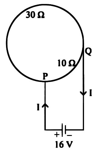
A circular coil of radius R has a resistance of 40Ω. Figure shows two points P and Q on the circumference separated by a distance 2πR which are connected to a 16 V battery with internal resistance of 0.5Ω. What is the value of current I flowing through the circuit?
Show answer and solution
Answer: (b)
Resistance is proportional to arc length. From the figure the two arcs between P and Q are 30Ω and 10Ω.
Combination of Resistors · Wires bent into loops & polygons
A uniform metallic wire has a resistance of 18 Ω and is bent into an equilateral triangle. Then, the resistance between any two vertices of the triangle is -
Combination of Resistors · Wires bent into loops & polygons
A metal wire of resistance 3 Ω is elongated to make a uniform wire of double its previous length. This new wire is now bent and the ends joined to make a circle. If two points on this circle make an angle 60° at the centre, the equivalent resistance between these two points will be :-
Show answer and solution
Answer: (d)
Doubling length (volume constant): R′=4×3=12Ω.
A 60∘ arc is 61 of the circle: 2Ω; the rest is 10Ω.
Combination of Resistors · Networks, symmetry & infinite ladders
In the given circuit all resistances are of value R ohm each. The equivalent resistance between A and B is:
Show answer and solution
Answer: (a)
Find the plain wires: the middle horizontal wire, the central vertical wire and the lower-left horizontal wire join the left-middle, centre, bottom-left and bottom-centre dots into one node.
So the resistor from A and the resistor from B both end on this same node; the rest of the network is attached only to that one node, so it carries no current.
Only the two series resistors at A and at B remain: RAB=R+R=2R.
Combination of Resistors · Networks, symmetry & infinite ladders
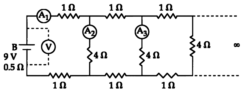
A 9 V battery with internal resistance of 0.5 Ω is connected across an infinite network as shown in the figure. All ammeters A1, A2,3 and voltmeter V are ideal.
Choose correct statement.
Show answer and solution
Answer: (a)
Each section of the ladder is 1Ω+1Ω in series with a 4Ω shunt. For an infinite ladder, adding one section does not change R∞.
R∞=2+4+R∞4R∞⇒R∞2−2R∞−8=0⇒R∞=4Ω
I=4+0.59=2 A, so A1 reads 2 A.
Voltmeter reads terminal voltage V=9−2×0.5=8 V, so (c) and (d) are wrong.
Combination of Resistors · Series & parallel combinations
Two metal wires of identical dimensions are connected in series. If σ1 and σ2 are their conductivities, the effective conductivity of the combination is
Show answer and solution
Answer: (c)
R=σAl. In series the combination has length 2l and area A.
Combination of Resistors · Wires bent into loops & polygons
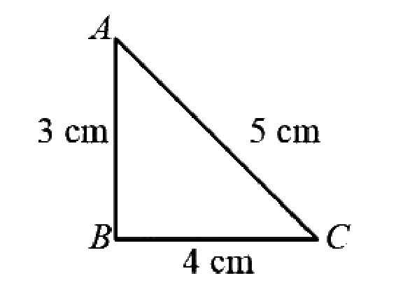
A 12 cm wire is given a shape of a right angled triangle ABC having sides 3 cm, 4 cm and 5 cm as shown in the figure. The resistance between two ends (AB, BC, CA) of the respective sides are measured one by one. Their ratio is
Show answer and solution
Answer: (b)
Let resistance per cm be r. Across a side of length x: x is in parallel with 12−x.
Combination of Resistors · Wires bent into loops & polygons
A letter 'A' is constructed of a uniform wire with resistance 1.0Ω per cm. The sides of the letter are 20 cm and the cross piece in the middle is 10 cm long. The apex angle is 60°. The resistance between the ends of the legs is close to:
Show answer and solution
Answer: (d)
With apex angle 60∘, the 10 cm cross piece joins the midpoints of the 20 cm legs. Each half-leg =10Ω, cross piece =10Ω.
Between the midpoints: cross piece 10Ω in parallel with the upper halves 10+10=20Ω: 3010×20=320Ω.
Combination of Resistors · Wires bent into loops & polygons
A ring is made of a wire having a resistance R0 = 12 Ω. Find the points A and B, as shown in the figure, at which a current carrying conductor should be connected so that the resistance R of the sub circuit between these point is equal to 38Ω.
Show answer and solution
Answer: (d)
Let the arcs be R1 and R2: R1+R2=12 and 12R1R2=38, so R1R2=32.
Combination of Resistors · Wires bent into loops & polygons
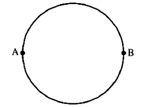
A wire of resistance 12 ohms per meter is bent to form a complete circle of radius 10 cm. The resistance between its two diametrically opposite points, A and B as shown in the figure is
Show answer and solution
Answer: (d)
Length =2πr=2π×0.1=0.2π m, so total R=12×0.2π=2.4πΩ.
Diametrically opposite points: two halves in parallel, RAB=4R.
Combination of Resistors · Wires bent into loops & polygons
When a wire of uniform cross-section a length l and resistance R is bent into a complete circle. resistance between any two of diametrically opposite points will be
Show answer and solution
Answer: (a)
Diametrically opposite points split the circle into two halves of 2R each.
Combination of Resistors · Series & parallel combinations
Resistance n, each of r ohm, when connected in parallel give an equivalent resistance of R ohm. If these resistances were connected in series, the combination would have a resistance in ohms, equal to
Combination of Resistors · Series & parallel combinations
The resistance of the series combination of two resistances is S. When they are joined in parallel the total resistance is P. If S=nP then the minimum possible value of n is
Show answer and solution
Answer: (c)
S=R1+R2, P=R1+R2R1R2, so n=PS=R1R2(R1+R2)2.
By AM–GM, (R1+R2)2≥4R1R2, so n≥4 (equality when R1=R2).
Combination of Resistors · Series & parallel combinations
An electric current is passed through a circuit containing two wires of the same material, connected in parallel. If the lengths and radii are in the ratio of 34 and 32, then the ratio of the current passing through the wires will be
Combination of Resistors · Networks, symmetry & infinite ladders
Five equal resistances each of resistances R are connected as shown in the figure. A battery of V volts is connected between A and B. The current flowing in AFCEB will be
Show answer and solution
Answer: (c)
A is joined to F and B to E. Between F and E there are two paths, F–C–E and F–D–E, each 2R, with CD as a bridge.
By symmetry C and D are at the same potential (balanced bridge), so CD carries no current.
Each path gets voltage V, so current in FCE =2RV.
Combination of Resistors · Series & parallel combinations
Two wires of the same metal have same length, but their cross-sections are in the ratio 3:1. They are joined in series. The resistance of thicker wire is 10Ω. The total resistance of the combination will be
Combination of Resistors · Wires bent into loops & polygons
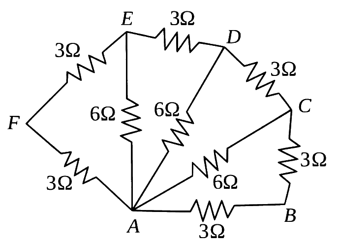
Six resistors of 3Ω each are connected along the sides of a hexagon and three resistors of 6Ω each are connected along AC,AD and AE as shown in the figure. The equivalent resistance between A and B is equal to
Show answer and solution
Answer: (a)
Start from F: AF+FE=6Ω, in parallel with AE=6Ω gives 3Ω between A and E.
Add ED: 3+3=6, parallel with AD=6 gives 3Ω between A and D.
Add DC: 3+3=6, parallel with AC=6 gives 3Ω between A and C.
Combination of Resistors · Series & parallel combinations
You are given several identical resistances each of value R=10Ω and each capable of carrying a maximum current of one ampere. It is required to make a suitable combination of these resistances of 5Ω which can carry a current of 4 ampere. The minimum number of resistances of the type R that will be required for this job is
Show answer and solution
Answer: (c)
Each resistor carries at most 1 A, so 4 A needs 4 parallel branches carrying 1 A each.
4 equal branches give 5Ω if each branch is 4×5=20Ω, i.e. two 10Ω in series.
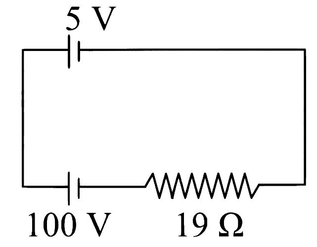
A resistor is connected to a battery of 12 V emf and internal resistance 2Ω. If the current in the circuit is 0.6 A, the terminal voltage of the battery is:
When an external resistance of 5Ω is connected across terminals of a cell, a current of 0.25 A flows through it. When the 5Ω resistor is replaced by a 2Ω resistor, a current of 0.5 A flows through it. The internal resistance of the cell is Ω.
Numerical answer type. Work it out, then open the answer.
Cells: EMF, Internal Resistance & Combinations · Cells in series & parallel
For the two cells having same EMF E and internal resistance r, the current passing through the external resistor 6Ω is same when both the cells are connected either in parallel or in series. The value of internal resistance r is Ω.
Cells: EMF, Internal Resistance & Combinations · Cells in series & parallel
Two cells of emfs 1 V and 2 V and internal resistance 2Ω and 1Ω, respectively connected in parallel, gave a current of 1 A through an external resistance. If the polarity of one cell is reversed, then value of current through the external resistance will be 5α A. The value of α is ______.
Numerical answer type. Work it out, then open the answer.
Cells: EMF, Internal Resistance & Combinations · Cells in series & parallel
Two cells of emfs 1 V and 2 V and internal resistances 2Ω and 1Ω, respectively, are connected in series with an external resistance of 6Ω. The total current in the circuit is I1. Now the same two cells in parallel configuration are connected to same external resistance. In this case, the total current drawn is I2. The value of (I2I1) is 3x. The value of x is___________.
Numerical answer type. Work it out, then open the answer.
Cells: EMF, Internal Resistance & Combinations · Cells in series & parallel
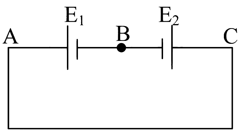
Two cells E1 and E2 having equal e.m.f ' E ' and internal resistances r1 and r2(r1>r2) respectively are connected in series. This combination is connected to an external resistance ' R '. It is observed that the potential difference across the cell E1 becomes zero. The value of R will be
Cells: EMF, Internal Resistance & Combinations · Cells in series & parallel
Given below are two statements:
Statement-I: The equivalent emf of two nonideal batteries connected in parallel is smaller than either of the two emfs.
Statement-II: The equivalent internal resistance of two nonideal batteries connected in parallel is smaller than the internal resistance of either of the two batteries.
In the light of the above statements, choose the correct answer from the options given below.
Show answer and solution
Answer: (a)
Statement I: Eeq=r1+r2E1r2+E2r1 is a weighted average, so it lies between E1 and E2, not below both. False.
Statement II: req=r1+r2r1r2 is smaller than each of r1, r2. True.
So the answer is (a) Statement-I is false but Statement-II is true.
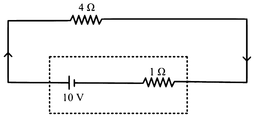
The terminal voltage of the battery, whose emf is 10 V and internal resistance 1Ω, when connected through an external resistance of 4Ω as shown in the figure is:
Cells: EMF, Internal Resistance & Combinations · Cells in series & parallel
Two cells are connected in opposition as shown. Cell E1 is of 8 V emf and 2Ω internal resistance; the cell E2 is of 2 V emf and 4Ω internal resistance. The terminal potential difference of cell E2 is __________ V.
Numerical answer type. Work it out, then open the answer.
Show answer and solution
Answer: 6
Cells in opposition, no external resistor: I=r1+r2E1−E2=2+48−2=1 A.
Current enters E2 at its positive terminal, so E2 is being charged.
Cells: EMF, Internal Resistance & Combinations · Cells in series & parallel
Two cells E1 and E2 having equal EMF 'E' and internal resistances r1 and r2(r1>r2) respectively are connected in series. This combination is connected to an external resistance 'R'. It is observed that the potential difference across the cell E1 becomes zero. The value of 'R' will be
Cells: EMF, Internal Resistance & Combinations · Cells in series & parallel
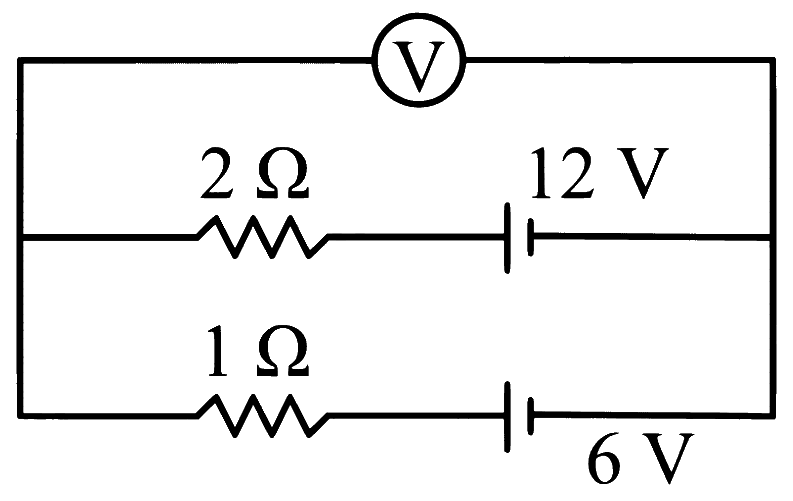
Two batteries, one of e.m.f. 12 V and internal resistance 2Ω and other of e.m.f. 6 V and internal resistance 1Ω, are connected as shown in the figure. What will be the reading of the voltmeter 'V'?
Show answer and solution
Answer: (b)
From the figure both batteries have their positive terminals on the same side, so they are in parallel.
Cells: EMF, Internal Resistance & Combinations · Cells in series & parallel
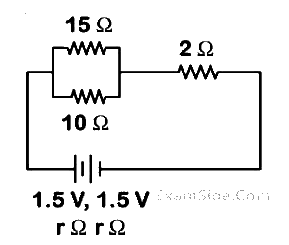
Two identical cells each of emf 1.5 V are connected in series across a 10Ω resistance. An ideal voltmeter connected across 10Ω resistance reads 1.5 V. The internal resistance of each cell is __________ Ω.
Numerical answer type. Work it out, then open the answer.
Cells: EMF, Internal Resistance & Combinations · Cells in series & parallel
Two identical cells, when connected either in parallel or in series gives same current in an external resistance 5Ω. The internal resistance of each cell will be ___________ Ω.
Numerical answer type. Work it out, then open the answer.
Cells: EMF, Internal Resistance & Combinations · Cells in series & parallel
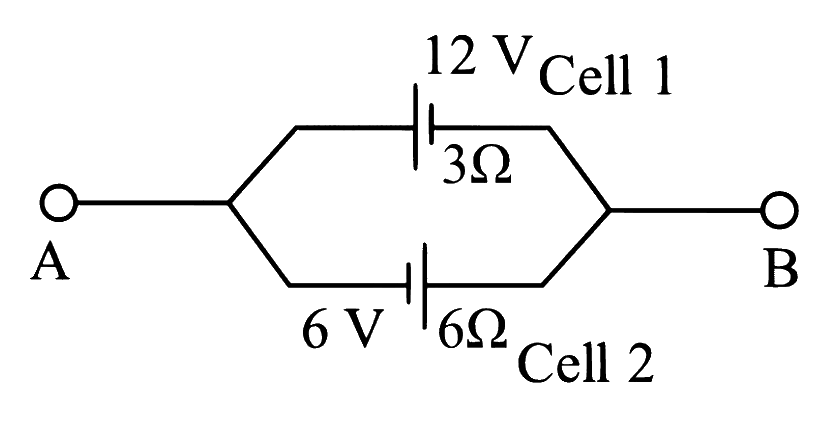
Two cells are connected between points A and B as shown. Cell 1 has emf of 12 V and internal resistance of 3Ω. Cell 2 has emf of 6V and internal resistance of 6Ω. An external resistor R of 4Ω is connected across A and B. The current flowing through R will be ____________ A.
Numerical answer type. Work it out, then open the answer.
Show answer and solution
Answer: 1
From the figure the two cells are in parallel with opposite polarity.
Eeq=1/r1+1/r2E1/r1−E2/r2=1/3+1/612/3−6/6=1/23=6 V
Cells: EMF, Internal Resistance & Combinations · Cells in series & parallel
Two sources of equal emfs are connected in series. This combination is connected to an external resistance R. The internal resistances of the two sources are r1 and r2(r1>r2). If the potential difference across the source of internal resistance r1 is zero, then the value of R will be:
Cells: EMF, Internal Resistance & Combinations · Cells in series & parallel
The combination of two identical cells, whether connected in series or parallel combination provides the same current through an external resistance of 2Ω. The value of internal resistance of each cell is
Show answer and solution
Answer: (a)
Series: I=2+2r2E; parallel: I=2+r/2E
Equal: 2(2+2r)=2+2r⇒4+r=2+2r
r=2Ω. So the answer is (a). (In general, equal currents need r=R.)
Cells: EMF, Internal Resistance & Combinations · Cells in series & parallel
Two cells of same emf but different internal resistances r1 and r2 are connected in series with a resistance R. The value of resistance R, for which the potential difference across second cell is zero, is:
Show answer and solution
Answer: (a)
Series cells: I=R+r1+r22E.
Terminal p.d. of second cell is zero: E−Ir2=0⇒I=r2E.
Cells: EMF, Internal Resistance & Combinations · Cells in series & parallel
Two identical cells each of emf 1.5 V are connected in parallel across a parallel combination of two resistors each of resistance 20 Ω. A voltmeter connected in the circuit measures 1.2 V. The internal resistance of each cell is:
Show answer and solution
Answer: (c)
Two identical cells in parallel: Eeq=1.5 V, req=2r.
External resistance =20∥20=10Ω, so I=RV=101.2=0.12 A.
Cells: EMF, Internal Resistance & Combinations · Maximum power transfer
A cell sends a current through a resistance 4Ω for time t and sends current through another resistance 16Ω for the same time t. If the same amount of heat is developed in both the resistances, then the internal resistance of the cell is _____ Ω
Numerical answer type. Work it out, then open the answer.
Show answer and solution
Answer: 8
Heat =I2Rt=(R+r)2E2Rt; equal heat for R1 and R2 gives r=R1R2.
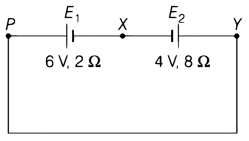
A cell E1 of emf 6V and internal resistance 2Ω is connected with another cell E2 of emf 4V and internal resistance 8Ω (as shown in the figure). The potential difference across points X and Y is:
Show answer and solution
Answer: (c)
From the figure both negative terminals face X, so the cells oppose: Enet=6−4=2 V.
I=2+82=0.2 A, driven by E1.
Across E1 (discharging): VP−VX=6−0.2×2=5.6 V, and VP=VY (same wire).
Check with E2 (being charged): 4+0.2×8=5.6 V. So the answer is (c) 5.6 V.
In an electric circuit, a cell of certain emf provides a potential difference of 1.25 V across a load resistance of 5Ω. However, it provides a potential difference of 1 V across a load resistance of 2Ω. The emf of the cell is given by 10x V. Then the value of x is ______________.
Numerical answer type. Work it out, then open the answer.
Cells: EMF, Internal Resistance & Combinations · Cells in series & parallel
Five identical cells each of internal resistance 1Ω and emf 5V are connected in series and in parallel with an external resistance 'R'. For what value of 'R', current in series and parallel combination will remain the same?
Cells: EMF, Internal Resistance & Combinations · Cells in series & parallel
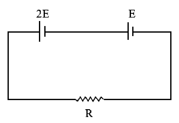
Two cells of emf 2E and E with internal resistance r1 and r2 respectively are connected in series to an external resistor R (see figure). The value of R, at which the potential difference across the terminals of the first cell becomes zero is
Show answer and solution
Answer: (b)
Both cells aid each other: I=R+r1+r23E.
Terminal p.d. of first cell is zero: 2E−Ir1=0⇒I=r12E.
Cells: EMF, Internal Resistance & Combinations · Cells in series & parallel
First, a set of n equal resistors of 10 Ω each are connected in series to a battery of emf 20V and internal resistance 10Ω. A current I is observed to flow. Then, the n resistors are connected in parallel to the same battery. It is observed that the current is increased 20 times, then the value of n is ................
Numerical answer type. Work it out, then open the answer.
Cells: EMF, Internal Resistance & Combinations · Cells in series & parallel
The series combination of two batteries, both of the same emf 10 V, but different internal resistance of 20Ω and 5Ω, is connected to the parallel combination of two resistors 30Ω and R Ω. The voltage difference across the battery of internal resistance 20Ω is zero, the value of R (in Ω) is: _______
Numerical answer type. Work it out, then open the answer.
Show answer and solution
Answer: 30
P.d. across the 20Ω battery is zero: 10−20I=0⇒I=0.5 A.
Cells: EMF, Internal Resistance & Combinations · Maximum power transfer
A battery of 3.0 V is connected to a resistor dissipating 0.5 W of power. If the terminal voltage of the battery is 2.5 V, the power dissipated within the internal resistance is:
Show answer and solution
Answer: (c)
Power in load P=VI⇒I=2.50.5=0.2 A.
Drop across internal resistance =E−V=3.0−2.5=0.5 V.
Cells: EMF, Internal Resistance & Combinations · Maximum power transfer
A cell of internal resistance r drives current through an external resistance R. The power delivered by the cell to the external resistance will be maximum when :-
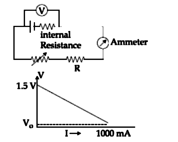
To verify Ohm's law, a student connects the voltmeter across the battery as, shown in the figure. The measured voltage is plotted as a function of the current, and the following graph is obtained:
If V0 is almost zero, identify the correct statement:
Show answer and solution
Answer: (b)
Voltmeter across the battery reads V=E−Ir.
Intercept at I=0: E=1.5 V
V≈0 at I=1 A: r=11.5=1.5Ω
So the answer is (b) emf 1.5 V and internal resistance 1.5Ω.
Cells: EMF, Internal Resistance & Combinations · Cells in series & parallel
A set of n equal resistors, of value R each, are connected in series to a battery of emf E and internal resistance R. The current drawn is I. Now, the n resistors are connected in parallel to the same battery. Then the current drawn from battery becomes 10I. The value of n is
Cells: EMF, Internal Resistance & Combinations · Cells in series & parallel
A battery consists of a variable number n of identical cells (having internal resistance r each) which are connected in series. The terminals of the battery are short-circuited and the current I is measured. Which of the graphs shows the correct relationship between I and n?
Show answer and solution
Answer: (a)
Short circuit: I=nrnE=rE
I does not depend on n, so the graph is a horizontal line.
Cells: EMF, Internal Resistance & Combinations · Cells in series & parallel
Two batteries with e.m.f 12 V and 13 V are connected in parallel across a load resistor of 10 Ω. The internal resistances of the two batteries are 1 Ω and 2 Ω respectively. The voltage across the load lies between:
Show answer and solution
Answer: (c)
Cells in parallel with a load (Millman): V=1/r1+1/r2+1/RE1/r1+E2/r2.
Cells: EMF, Internal Resistance & Combinations · Cells in series & parallel
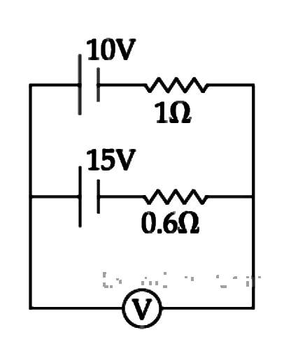
A 10V battery with internal resistance 1Ω and a 15V battery with internal resistance 0.6 Ω are connected in parallel to a voltmeter (see figure). The reading in the voltmeter will be close to:
Show answer and solution
Answer: (c)
An ideal voltmeter draws no current, so it reads the equivalent emf of the parallel cells.
A d.c. main supply of e.m.f. 220 V is connected across a storage battery of e.m.f. 200 V through a resistance of 1 Ω. The battery terminals are connected to an external resistance 'R'. The minimum value of 'R', so that a current passes through the battery to charge it is:
Show answer and solution
Answer: (c)
Battery (200 V) and R are in parallel, fed by 220 V through 1Ω.
At the threshold, battery current is zero and its terminal voltage is 200 V: supply current =1220−200=20 A, all through R.
Charging needs R200<20⇒R>10Ω
The smallest option above 10Ω is 11Ω. So the answer is (c).
A dc source of emf E1=100 V and internal resistance r=0.5Ω, a storage battery of emf E2=90 V and an external resistance R are connected as shown in figure. For what value of R no current will pass through the battery?
Show answer and solution
Answer: (c)
No current in E2 means voltage across R equals E2=90 V.
Current from E1: I=0.5100−90=20 A, all of which flows through R.
A cell having an emf ε and internal resistance r is connected across a variable external resistance R. As the resistance R is increased, the plot of potential difference V across R is given by
Show answer and solution
Answer: (c)
V=IR=R+rεR=1+r/Rε
At R=0, V=0; as R increases V rises and approaches ε asymptotically (curve bending over).
A current of 2 A flows through a 2 Ω resistor when connected across a battery. The same battery supplies a current of 0.5 A when connected across a 9 Ω resistor. The internal resistance of the battery is
A student measures the terminal potential difference (V) of a cell (of emf ε and internal resistance r) as a function of the current (I) flowing through it. The slope, and intercept, of the graph between V and I, then respectively, equal
Cells: EMF, Internal Resistance & Combinations · Cells in series & parallel
Two cells, having the same e.m.f. are connected in series through an external resistance R. Cells have internal resistances r1 and r2 (r1 > r2) respectively. When the circuit is closed, the potential difference across the first cell is zero. The value of R is
Show answer and solution
Answer: (b)
I=R+r1+r22E
P.d. across first cell zero: E=Ir1⇒R+r1+r22Er1=E
Cells: EMF, Internal Resistance & Combinations · Cells in series & parallel
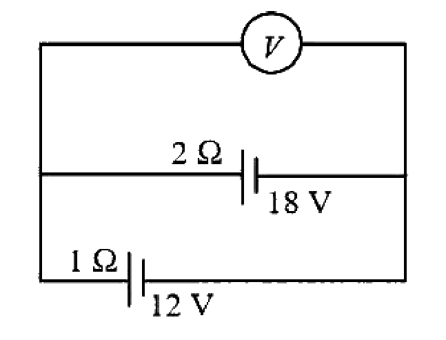
Two batteries, one of emf 18 volts and internal resistance 2 Ω and the other of emf 12 volts and internal resistance 1 Ω, are connected as shown. The voltmeter V will record a reading of
Show answer and solution
Answer: (d)
From the figure both batteries are connected in parallel with like terminals together.
Cells: EMF, Internal Resistance & Combinations · Cells in series & parallel
Two sources of equal emf are connected to an external resistance R. The internal resistances of the two sources are R1 and R2(R2>R1). If the potential difference across the source having internal resistance R2 is zero, then
For a cell terminal potential difference is 2.2V when circuit is open and reduce to 1.8 V when cell is connected to a resistance of R = 5 Ω. Determine internal resistance of cell (r)
A cell has an emf 1.5 V. When connected across an external resistance of 2Ω, the terminal potential difference falls to 1.0 V. The internal resistance of the cell is
Cells: EMF, Internal Resistance & Combinations · Maximum power transfer
A battery of e.m.f 10 V and internal resistance 0.5Ω is connected across a variable resistance R. The value of R for which the power delivered in it is maximum is given by
Show answer and solution
Answer: (a)
Maximum power transfer theorem: power in R is maximum when R=r.
Cells: EMF, Internal Resistance & Combinations · Maximum power transfer
Two identical batteries each of e.m.f 2 V and internal resistance 1Ω are available to produce heat in an external resistance by passing a current through it. The maximum power that can be developed across R using these batteries is
Show answer and solution
Answer: (b)
Maximum power in R occurs when R=req: Pmax=4reqEeq2.
Which one of the following is not a measurable quantity?
Show answer and solution
Answer: (d)
Only differences of potential can be measured (a voltmeter is always connected between two points); absolute potential at a point depends on the chosen zero.
Resistance and voltage difference are measured directly; displacement current is treated as measurable through its magnetic effect.
A galvanometer of resistance 100Ω gives full scale deflection for a current of 1 mA. It is converted into an ammeter of range 0−10 A. The shunt required is:
A voltmeter with internal resistance of xΩ can be used to measure upto 20 V. In order to increase its measuring range to 30 V, the required modification is to ______.
Show answer and solution
Answer: (a)
To raise a voltmeter's range a resistance is added in series: R=RV(VV′−1).
A moving coil galvanometer of resistance 100Ω shows a full scale deflection for a current of 1 mA. The value of resistance required to convert this galvanometer into an ammeter, showing full scale deflection for a current of 5 mA, is Ω
Kirchhoff's Laws & Measuring Instruments · Potential difference between points
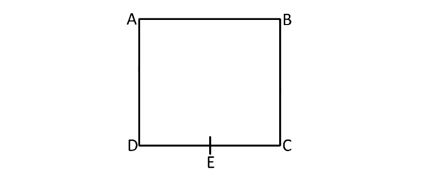
A uniform metallic wire having resistance 4Ω is bent to form a square loop (ABCD) (see figure). A resistance of 2Ω is connected between points B and D and a battery of 2 V is connected across points A and C as shown in the figure. Now the value of current (l) is:
Show answer and solution
Answer: (a)
Each side of the square has 44=1Ω.
AB : BC = AD : DC = 1 : 1, so the bridge is balanced and the 2Ω in BD carries no current.
Two resistors of 100Ω each are connected in series with a 9 V battery. A voltmeter of 400Ω resistance is connected to measure the voltage drop across one of the resistors. The voltmeter reading is ______ V.
By connecting a resistance of 980Ω in series with a galvanometer, it is converted into a voltmeter of a certain range. When the resistance of 470Ω is connected in series, the range is halved. The resistance of the galvanometer is
Show answer and solution
Answer: (b)
Voltmeter range V=Ig(G+R), with the same full-scale current Ig.
With a resistance 'X' connected in series with a galvanometer of resistance 100Ω, it acts as a voltmeter of range 0 - 15 V. To double the range, a resistance of 1500Ω is to be connected in series with 'X'. The value of 'X' in Ω is
The voltmeter has range 10 V and its internal resistance is 50Ω. To increase the range of voltmeter to 15 V, the resistance which is to be connected is
Show answer and solution
Answer: (d)
To raise a voltmeter's range a resistance is added in series: R=G(VV′−1).
Only 4% of the total current in the circuit passes through a galvanometer. If the resistance of the galvanometer is G, then the shunt resistance connected to the galvanometer is
Show answer and solution
Answer: (b)
Galvanometer and shunt are in parallel, so IgG=(I−Ig)S⇒S=I−IgIgG.
A galvanometer having a coil of resistance 30Ω need 20 mA of current for full-scale deflection. If a maximum current of 3 A is to be measured using this galvanometer, the resistance of the shunt to be added to the galvanometer should be X30Ω, where X is
Kirchhoff's Laws & Measuring Instruments · Potential difference between points
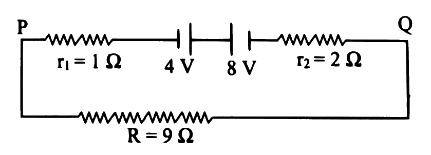
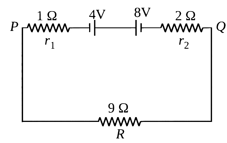
Two batteries of e.m.f 4 V and 8 V with internal resistance 1Ω and 2Ω respectively are connected in a circuit with a resistance of 9Ω as shown in the figure. The current and potential difference between the points ' P ' and ' Q ' is R=9Ω
Show answer and solution
Answer: (b)
The two cells face each other (+ to +), so they oppose: net emf =8−4=4 V.
Kirchhoff's Laws & Measuring Instruments · Potential difference between points
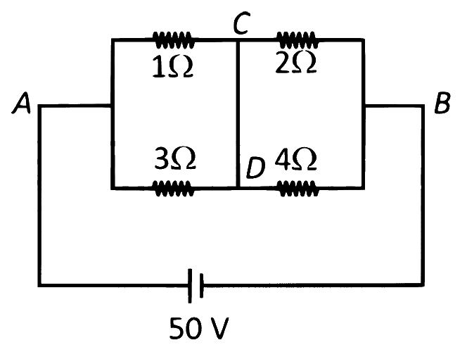
A constant voltage of 50 V is maintained between the points A and B of the circuit shown in the figure. The current through the branch CD of the circuit is:
Show answer and solution
Answer: (d)
1Ω∥3Ω=0.75Ω (between A-side and CD), 2Ω∥4Ω=34Ω (between CD and B-side).
Kirchhoff's Laws & Measuring Instruments · Potential difference between points
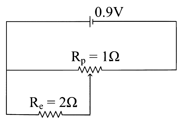
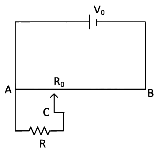
Sliding contact of a potentiometer is in the middle of the potentiometer wire having resistance Rp=1Ω as shown in the figure. An external resistance of Re=2Ω is connected via the sliding contact. The electric current in the circuit is:
Show answer and solution
Answer: (c)
Each half of the potentiometer is 0.5Ω; Re is in parallel with the left half.
When a resistance of 100Ω is connected in series with a galvanometer of resistance ' G ', its range is ' V '. To double its range, a resistance of 1000Ω is connected in series. The value of ' G ' is
Show answer and solution
Answer: (b)
Range V=Ig(G+R) with fixed Ig.
The intended reading is that the 1000Ω replaces the 100Ω: Ig(G+1000)=2Ig(G+100).
With a resistance ' X ' connected in series with a galvanometer of resistance 100Ω, it acts as a voltmeter of range 0−15 V. To double the range, a resistance of 1500Ω is to be connected in series with ' X '. The value of ' X ' in ohm is
The scale of a galvanometer is divided into 160 equal divisions. The galvanometer shows full scale deflection of 16 mA and maximum voltage is 80 mV. Now the range is changed so that galvanometer reads 160 V. The required resistance to be connected is
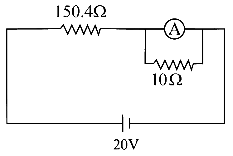
In the figure shown below, a resistance of 150.4Ω is connected in series to an ammeter A of resistance 240Ω. A shunt resistance of 10Ω is connected in parallel with the ammeter. The reading of the ammeter is___________mA.
Numerical answer type. Work it out, then open the answer.
Show answer and solution
Answer: 5
Ammeter and shunt in parallel: 250240×10=9.6Ω
Total resistance =150.4+9.6=160Ω, so I=16020=125 mA
Current through the ammeter coil: IA=125×25010=5 mA
A. The torsional constant in moving coil galvanometer has dimensions [ML2T−2] B. Increasing the current sensitivity may not necessarily increase the voltage sensitivity. C. If we increase number of turns (N) to its double (2N), then the voltage sensitivity doubles. D. MCG can be converted into an ammeter by introducing a shunt resistance of large value in parallel with galvanometer.
E. Current sensitivity of MCG depends inversely on number of turns of coil.
Choose the correct answer from the options given below:
Show answer and solution
Answer: (b)
A: τ=kθ and θ is dimensionless, so [k]=[ML2T−2]. True.
B: Vs=RIs; raising Is by more turns also raises R, so Vs may not rise. True.
C: N→2N doubles both Is and R, so Vs is unchanged. False.
D: an ammeter needs a small shunt, not a large one. False. E: Is=kNAB∝N, not inverse. False.
Two identical galvanometers are converted into an ammeter and into milliammeter. For the same current, the value of shunt of the ammeter as compared to that of milliammeter is
Show answer and solution
Answer: (a)
S=I−IgIgG, so for the same G and Ig a larger range I needs a smaller shunt.
An ammeter has a much larger range than a milliammeter.
In an ammeter, 0.25% of main current passes through the galvanometer. If the resistance of the galvanometer is ' G ', the resistance of ammeter will be
Two identical galvanometers are converted into voltmeter and millivoltmeter. As compared to the series resistance of voltmeter, the series resistance of millivoltmeter will be
Show answer and solution
Answer: (c)
Series resistance R=IgV−G, so it grows with the range V.
A millivoltmeter has a much smaller range than a voltmeter, so it needs a smaller series resistance.
The range of voltmeter of resistance ' G ' Ω is ' V ' volt. The resistance required to be connected in series with it in order to convert it into a voltmeter of range ' nV ' volt, will be
A galvanometer has a coil of resistance 200Ω with a full scale deflection at 20μA. The value of resistance to be added to use it as an ammeter of range (0−20) mA is:
A galvanometer has a resistance of 50Ω and it allows maximum current of 5 mA. It can be converted into voltmeter to measure up to 100 V by connecting in series a resistor of resistance:
A galvanometer having coil resistance 10Ω shows a full scale deflection for a current of 3 mA. For it to measure a current of 8 A, the value of the shunt should be:
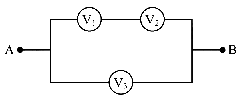
Three voltmeters, all having different internal resistances are joined as shown in figure. When some potential difference is applied across A and B, their readings are V1,V2 and V3. Choose the correct option.
Show answer and solution
Answer: (c)
V1 and V2 are in series, and that pair is in parallel with V3 across A and B.
Two resistances of 100Ω and 200Ω are connected in series with a battery of 4 V and negligible internal resistance. A voltmeter is used to measure voltage across 100Ω resistance, which gives reading as 1 V. The resistance of voltmeter must be _______ Ω.
Numerical answer type. Work it out, then open the answer.
Show answer and solution
Answer: 200
The 200Ω resistor gets 4−1=3 V, so I=2003=0.015 A.
When a resistance of 200Ω is connected in series with a galvanometer of resistance ' G ', its range is ' V '. To triple its range, a resistance of 2000Ω is connected in series. The value of ' G ' is
Show answer and solution
Answer: (d)
Range V=Ig(G+R) with fixed Ig.
The intended reading is that the 2000Ω replaces the 200Ω: G+2000=3(G+200).
When a resistance of 100Ω is connected in series with a galvanometer of resistance G, its range is V. To double its range a resistance of 1000Ω is connected in series. The value of G is
Show answer and solution
Answer: (a)
Range V=Ig(G+R) with fixed Ig.
The intended reading is that the 1000Ω replaces the 100Ω: G+1000=2(G+100).
A galvanometer may be converted into ammeter or a voltmeter. In which of the following cases the resistance of the device so obtained will be the largest?
Show answer and solution
Answer: (d)
An ammeter has a small shunt in parallel, so its resistance is less than G.
A voltmeter has a large series resistance: RV=IgV, which grows with the range.
Largest resistance: voltmeter of the higher range. So the answer is (d) voltmeter of range 10 V.
A galvanometer has resistance 80Ω and it is shunted with resistance 20Ω. If 20% of the main current flows through galvanometer, then what is the value of main current?
Show answer and solution
Answer: (c)
Shunt and galvanometer have the same p.d.: IgG=IsS.
Fraction through galvanometer =G+SS=10020=20%, true for any main current.
So the data cannot fix the main current; the key's value 1 A needs extra data (e.g. Ig=0.2 A).
When a galvanometer is shunted by a resistance ' s ', its current capacity increases ' n ' times. If the same galvanometer is shunted by another resistance ' s1 ', its capacity will increase to ' n1 ' times original current. The value of ' n1 ' is
When a galvanometer is shunted by a resistance ' S ', its current capacity increases ' n ' times. If the same galvanometer is shunted by another resistance S′, its current capacity increases to n′. The value of n′ in terms of n,S and S′ is
A galvanometer of resistance 100Ω when connected in series with 400Ω measures a voltage of upto 10 V. The value of resistance required to convert the galvanometer into ammeter to read upto 10 A is x×10−2Ω. The value of x is:
The deflection in moving coil galvanometer falls from 25 divisions to 5 divisions when a shunt of 24Ω is applied. The resistance of galvanometer coil will be:
Show answer and solution
Answer: (c)
Deflection falls from 25 to 5 divisions, so Ig=5I and the shunt carries 54I.
G and S are in parallel: IgG=(I−Ig)S⇒5IG=54I(24)
A galvanometer of resistance ' G ' is shunted by resistance of 'S' ohm. To keep the main current in the circuit unchanged the resistance to be put in series with Galvanometer is
Show answer and solution
Answer: (a)
Shunted galvanometer: G+SGS; it must still offer resistance G to keep the main current unchanged.
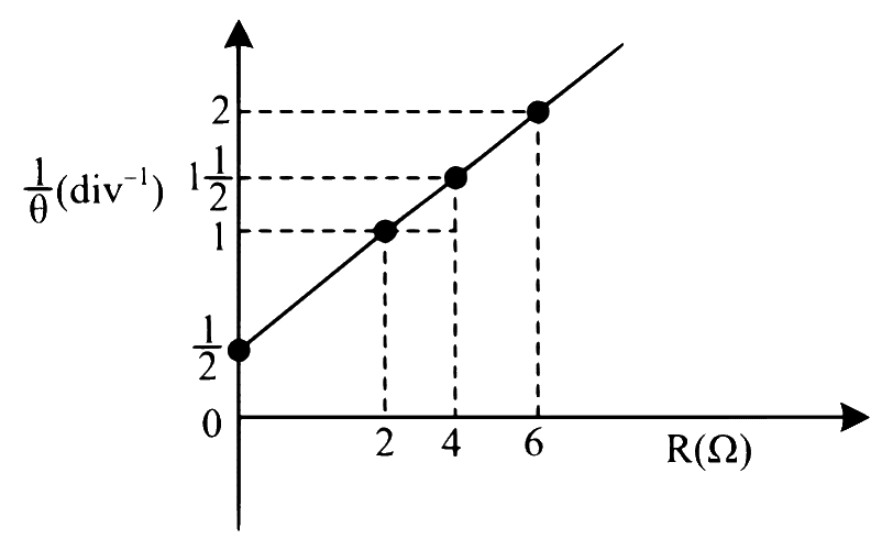
In the experiment to determine the galvanometer resistance by half-deflection method, the plot of 1/θ vs the resistance (R) of the resistance box is shown in the figure. The figure of merit of the galvanometer is _________ ×10−1 A/ division. [The source has emf 2 V]
Numerical answer type. Work it out, then open the answer.
Only 4% of the total current in the circuit passes through a galvanometer. If the resistance of the galvanometer is G, then the shunt resistance connected to the galvanometer is
Kirchhoff's Laws & Measuring Instruments · Potential difference between points
Figure shows a part of an electric circuit. The potentials at points a,b and c are 30 V,12 V and 2 V respectively. The current through the 20Ω resistor will be,
Show answer and solution
Answer: (c)
Let the junction potential be V. KCL: 1030−V=20V−12+30V−2
Kirchhoff's Laws & Measuring Instruments · Potential difference between points
As shown in the figure, a network of resistors is connected to a battery of 24V with an internal resistance of 3 Ω. The currents through the resistors R4 and R5 are I4 and I5 respectively. The values of I4 and I5 are:
Show answer and solution
Answer: (c)
R1∥R2=1Ω, R4∥R5=2520×5=4Ω
Total R=1+2+4+2+3=12Ω, I=1224=2 A
Current divides inversely with resistance: I4=2×255=52 A, I5=2×2520=58 A
Kirchhoff's Laws & Measuring Instruments · Potential difference between points
A network of four resistances is connected to 9 V battery, as shown in figure. The magnitude of voltage difference between the points A and B is __________ V.
Numerical answer type. Work it out, then open the answer.
Show answer and solution
Answer: 3
Each side of the bridge gets the full 9 V across 2+4=6Ω.
Drop from the left node to A (across 2Ω): 9×62=3 V
Drop from the left node to B (across 4Ω): 9×64=6 V
Given below are two statements: One is labelled as Assertion A and the other is labelled as Reason R.
Assertion A: For measuring the potential difference across a resistance of 600Ω, the voltmeter with resistance 1000Ω will be preferred over voltmeter with resistance 4000Ω.
Reason R: Voltmeter with higher resistance will draw smaller current than voltmeter with lower resistance.
In the light of the above statements, choose the most appropriate answer from the options given below.
Show answer and solution
Answer: (a)
A good voltmeter should draw as little current as possible, so it should have a much larger resistance than the 600Ω resistor.
The 4000Ω voltmeter disturbs the circuit less, so it is preferred: A is false.
For the same p.d., I=V/RV is smaller for larger RV: R is true.
A cell of emf 90 V is connected across series combination of two resistors each of 100Ω resistance. A voltmeter of resistance 400Ω is used to measure the potential difference across each resistor. The reading of the voltmeter will be:
When moving coil galvanometer (MCG) is converted into a voltmeter, the series resistance is 'n' times the resistance of galvanometer. How many times that of MCG the voltmeter is now capable of measuring voltage?
A galvanometer of resistance 20Ω gives a deflection of 5 divisions when 1 mA current flows through it. The galvanometer scale has 50 divisions. To convert the galvanometer into a voltmeter of range 25 volt, we should connect a resistance of
Show answer and solution
Answer: (b)
5 divisions per mA, so full scale (50 divisions) Ig=10 mA=0.01 A.
For designing a voltmeter of range 50 V and an ammeter of range 10 mA using a galvanometer which has a coil of resistance 54Ω showing a full scale deflection for 1 mA as in figure.
(A) for voltmeter R≈50 kΩ
(B) for ammeter r≈0.2Ω
(C) for ammeter r=6Ω
(D) for voltmeter R≈5 kΩ
(E) for voltmeter R≈500Ω
Choose the correct answer from the options given below:
Show answer and solution
Answer: (a)
Voltmeter: series R=IgV−G=10−350−54=49946Ω≈50 kΩ, so (A) is true.
Ammeter: shunt r=I−IgIgG=10−11×54=6Ω, so (C) is true.
When a resistance of 5Ω is shunted with a moving coil galvanometer, it shows a full scale deflection for a current of 250 mA, however when 1050Ω resistance is connected with it in series, it gives full scale deflection for 25 volt. The resistance of galvanometer is ____________ Ω.
Numerical answer type. Work it out, then open the answer.
The current sensitivity of moving coil galvanometer is increased by 25%. This increase is achieved only by changing in the number of turns of coils and area of cross section of the wire while keeping the resistance of galvanometer coil constant. The percentage change in the voltage sensitivity will be:
The number of turns of the coil of a moving coil galvanometer is increased in order to increase current sensitivity by 50%. The percentage change in voltage sensitivity of the galvanometer will be:
Show answer and solution
Answer: (a)
Is=kNAB∝N; coil resistance R∝N (more turns, more wire).
A student is provided with a variable voltage source V, a test resistor RT=10Ω, two identical galvanometers G1 and G2 and two additional resistors, R1=10MΩ and R2=0.001Ω. For conducting an experiment to verify Ohm's law, the most suitable circuit is:
Show answer and solution
Answer: (c)
Voltmeter across RT: galvanometer with the large resistance R1=10 MΩ in series, connected in parallel with RT.
Ammeter in series: galvanometer with the small shunt R2=0.001Ω in parallel.
Circuit (c) has G1+R1 across RT and G2∥R2 in the main line.
A galvanometer of resistance 200Ω is to be converted into an ammeter. The value of shunt resistance which allows 3% of the mains current through the galvanometer is equal to (nearly)
Kirchhoff's Laws & Measuring Instruments · Potential difference between points
The sliding contact C is at one fourth of the length of the potentiometer wire (AB) from A as shown in the circuit diagram. If the resistance of the wire AB is R0, then the potential drop (V) across the resistor R is
Show answer and solution
Answer: (b)
AC has 4R0 and is in parallel with R; CB has 43R0 in series.
RAC∥R=R0/4+R(R0/4)R=R0+4RR0R
Voltage divider: V=V0R0+4RR0R+43R0R0+4RR0R=4R+3(R0+4R)4V0R
Two resistors are connected in series across a battery as shown in figure. If a voltmeter of resistance 2000 Ω is used to measure the potential difference across 500 Ω resistor, the reading of the voltmeter will be ___________ V.
Numerical answer type. Work it out, then open the answer.
A teacher in his physics laboratory allotted an experiment to determine the resistance (G) of a galvanometer. Students took the observations for 31 deflection in the galvanometer. Which of the below is true for measuring value of G?
Show answer and solution
Answer: (b)
With the main current kept the same, 31 deflection means Ig=3I and the shunt carries 32I.
If n represents the actual number of deflections in a converted galvanometer of resistance G and shunt resistance S. Then the total current I when its figure of merit is K will be:
Show answer and solution
Answer: (d)
Current through galvanometer Ig=nK (figure of merit K = current per division).
A 16 Ω wire is bent to form a square loop. A 9V supply having internal resistance of 1Ω is connected across one of its sides. The potential drop across the diagonals of the square loop is _______________ × 10−1 V
Numerical answer type. Work it out, then open the answer.
Q382JEE Main 2021 · 25 JUL · SHIFT 2MediumOld syllabus
Kirchhoff's Laws & Measuring Instruments · Potential difference between points
The given potentiometer has its wire of resistance 10Ω. When the sliding contact is in the middle of the potentiometer wire, the potential drop across 2Ω resistor is:
Show answer and solution
Answer: (c)
Each half of the wire is 5Ω; the 2Ω is in parallel with the half on the A side.
A moving coil galvanometer is converted into an ammeter, reading upto 0.04 A by connecting a shunt of resistance '3r' across it and then into an ammeter reading upto 0.08 A, when a shunt of resistance 'r' is connected across it. What is the maximum current which can be sent through this galvanometer if no shunt is used?
A galvanometer has resistance 'G' Ω and 'Ig' is current flowing through it which produces full scale deflection. 'S1' is the value of shunt which converts it into an ammeter of range 0 to '3I' and 'S2' is the shunt value which converts it into an ammeter of range 0 to '4I', the ratio S2:S1 is
For full scale deflection of total 50 divisions, 50 mV voltage is required in galvanometer. The resistance of galvanometer if its current sensitivity is 2 div/mA will be:
A galvanometer of resistance G is converted into a voltmeter of range 0 – 1 V by connecting a resistance R1 in series with it. The additional resistance that should be connected in series with R1 to increase the range of the voltmeter to 0 – 2 V will be:
A galvanometer having a coil resistance 100 Ω gives a full scale deflection when a current of 1 mA is passed through it. What is the value of the resistance which can convert this galvanometer into a voltmeter giving full scale deflection for a potential difference of 10 V?
Two galvanometers A and B require currents of 4 mA and 7 mA, respectively to produce the same deflection of 20 divisions. If SA and SB are their sensitivities respectively, then
Show answer and solution
Answer: (b)
Current sensitivity S=Iθ (divisions per unit current).
SA=420=5 div/mA, SB=720≈2.86 div/mA.
A needs less current for the same deflection, so it is more sensitive.
A galvanometer is used in laboratory for detecting the null point in electrical experiments. If, on passing a current of 6 mA it produces a deflection of 2°, its figure of merit is close to:
Four resistances 40 Ω, 60 Ω, 90 Ω and 110 Ω make the arms of a quadrilateral ABCD. Across AC is a battery of emf 40 V and internal resistance negligible. The potential difference across BD in V is _______.
Numerical answer type. Work it out, then open the answer.
Show answer and solution
Answer: 2
Path ABC: 40+60=100Ω, current 0.4 A; path ADC: 90+110=200Ω, current 0.2 A.
Kirchhoff's Laws & Measuring Instruments · Potential difference between points
In the circuit, given in the figure currents in different branches and value of one resistor are shown. Then potential at point B with respect to the point A is:
Show answer and solution
Answer: (c)
Take VA=0. Crossing the 1 V cell from − to + towards C: VC=1 V.
At D: 2 A arrives from B, 1 A leaves towards E, so 1 A flows D to C through 2Ω: VD=1+2=3 V.
Crossing the 2 V cell from + (D side) to − (B side): VB=3−2=1 V
Two resistors 400Ω and 800Ω are connected in series across a 6 V battery. The potential difference measured by a voltmeter of 10 kΩ across 400 Ω resistor is close to:
An ammeter of resistance 20Ω gives full scale deflection, when 1 mA current flows through it. What is the maximum current that can be measured by connecting 4 resistors each of 16Ω in parallel with the ammeter?
A galvanometer has resistance of 100Ω and a current of 10 mA produces full scale deflection in it. The resistance to be connected in series, to get a voltmeter of range 50 volt is
A moving coil galvanometer allows a full scale current of 10–4 A. A series resistance of 2 MΩ is required to convert the above galvanometer into a voltmeter of range 0-5 V. Therefore the value of shunt resistance required to convert the above galvanometer into an ammeter of range 0-10 mA is:
Show answer and solution
Answer: (d)
For the voltmeter: Ig(G+R)=5⇒G+R=10−45=5×10⁴Ω.
With R=2 MΩ this gives G=5×10⁴−2×10⁶<0, which is impossible.
So the data is inconsistent and no option fits: the answer is (d) None of the options are correct.
The resistance of a galvanometer is 50 ohm and the maximum current which can be passed through it is 0.002 A. What resistance must be connected to it in order to convert it into an ammeter of range 0 – 0.5 A?
A moving coil galvanometer has resistance 50Ω and it indicates full deflection at 4mA current. A voltmeter is made using this galvanometer and a 5 kΩ resistance. The maximum voltage, that can be measured using this voltmeter, will be close to:
In the given circuit diagram, the currents, I1 = – 0.3 A, I4 = 0.8 A and I5 = 0.4 A, are flowing as shown. The currents I2, I3 and I6, respectively, are:
Kirchhoff's Laws & Measuring Instruments · Potential difference between points
For the circuit shown, with R1 = 1.0 Ω, R2 = 2.0 Ω, E1 = 2 V and E2 = E3 = 4 V, the potential difference between the points 'a' and 'b' is approximately (in V):
Show answer and solution
Answer: (a)
Three branches lie between a and b: (E1=2, 2R1=2Ω), (E2=4, R2=2Ω), (E3=4, 2R1=2Ω), all with + towards a.
The actual value of resistance R, shown in the figure is 30Ω. This is measuered in an experiment as shown using the standard formula R = IV, where V and I are the readings of the voltmeter and ammeter, respectively. If the measured value of R is 5% less, then the internal resistance of the voltmeter is -
Show answer and solution
Answer: (a)
The voltmeter is across R, so the ammeter reads the current through R∥RV; measured value =R+RVRRV.
In the given circuit the internal resistance of the 18 V cell is negligible. If R1 = 400 Ω, R3 = 100 Ω and R4 = 500 Ω and the reading of an ideal voltmeter across R4 is 5V, then the value of R2 will be:
Show answer and solution
Answer: (a)
Current in R3,R4 branch: 5005=0.01 A; branch p.d. =0.01×600=6 V (this is also across R2).
P.d. across R1=18−6=12 V, so total current =40012=0.03 A.
A moving coil galvanometer, having a resistance G, produces full scale deflection when a current Ig flows through it. This galvanometer can be converted into (i) an ammeter of range 0 to I0(I0 > Ig) by connecting a shunt resistance RA to it and (ii) into a voltmeter of range 0 to V (V = GI0) by connecting a series resistance RV to it. Then,
Show answer and solution
Answer: (d)
Ammeter shunt: RA=I0−IgIgG
Voltmeter series resistance: RV=IgV−G=IgGI0−G=IgG(I0−Ig)
A galvanometer, whose resistance is 50 ohm, has 25 divisions in it. When a current of 4 × 10⁻⁴ A passes through it, its needle ( pointer) deflects by one division. To use this galvanometer as a voltmeter of range 2.5 V, it should be connected to a resistance of:
A galvanometer of resistance 100 Ω has 50 divisions on its scale and has sensitivitv of 20 μA/division. It is to be converted to a voltmeter with three ranges of 0-2V, 0-10 V and 0-20 V. The appropriate circuit to do so is
Show answer and solution
Answer: (c)
Ig=50×20μA=1 mA
2 V: total 10−32=2000Ω⇒R1=2000−100=1900Ω
10 V: total 10000Ω⇒R2=10000−2000=8000Ω
20 V: total 20000Ω⇒R3=20000−10000=10000Ω
So the answer is (c) R1=1900, R2=8000, R3=10000Ω.
A galvanometer having a resistance of 20 Ω and 30 divisions on both sides has figure of merit 0.005 ampere/division. The resistance that should be connected in series such that it can be used as a voltmeter upto 15 volt, is:
Show answer and solution
Answer: (c)
Full scale current (30 divisions one side) Ig=30×0.005=0.15 A
The galvanometer deflection, when key K1 is closed but K2 is open, equals θ0 (see figure). On closing K2 also and adjusting R2 to 5Ω, the deflection in galvanometer becomes 5θ0. The resistance of the galvanometer is, then, given by [Neglect the internal resistance of battery]:
A galvanometer with its coil resistance 25 Ω requires a current of 1 mA for its full deflection. In order to construct an ammeter to read upto a current of 2 A, the approximate value of the shunt resistance should be:
In a circuit for finding the resistance of a galvanometer by half deflection method, a 6 V battery and a high resistance of 11 kΩ are used. The figure of merit of the galvanometer is 60 μA/division. In the absence of shunt resistance, the galvanometer produces a deflection of θ = 9 divisions when current flows in the circuit. The value of the shunt resistance that can cause the deflection of θ/2, is closest to:
Show answer and solution
Answer: (d)
No shunt: I=9×60μA=540μA=11000+G6
11000+G=11111⇒G=111Ω
Half deflection method with very large series resistance: S≈G (exact working gives S≈110Ω).
When a current of 5 mA is passed through a galvanometer having a coil of resistance 15Ω, it shows full scale deflection. The value of the resistance to be put in series with the galvanometer to convert it into a voltmeter of range 0 – 10V is:
A galvanometer having a coil resistance of 100Ω gives a full scale deflection, when a currect of 1 mA is passed through it. The value of the resistance, which can convert this galvanometer into ammeter giving a full scale deflection for a current of 10 A, is:
A galvanometer has a 50 division scale. Battery has no internal resistance. It is found that there is deflection of 40 divisions when R = 2400 Ω. Deflection becomes 20 divisions when resistance taken from resistance box is 4900 Ω. Then we can conclude:
Show answer and solution
Answer: (c)
G is in series with R and the 2 V cell, so I=R+G2 and deflection ∝I.
2040=2400+G4900+G⇒4800+2G=4900+G⇒G=100Ω, so (a) is false.
At 40 div: I=25002=0.8 mA, so K=400.8 mA=20μA/div.
Full scale =50×20μA=1 mA (b false); for 10 div, I=0.2 mA, R=10000−100=9900Ω (d false).
A 50 Ω resistance is connected to a battery of 5 V. A galvanometer of resistance 100 Ω is to be used as an ammeter to measure current through the resistance, for this a resistance rs is connected to the galvanometer. Which of the following connections should be employed if the measured current is within 1% of the current without the ammeter in the circuit?
Show answer and solution
Answer: (a)
True current I=505=0.1 A. To stay within 1%, 50+RA50≥0.99⇒RA≤0.505Ω.
An ammeter needs a small shunt in parallel with the galvanometer.
With rs=0.5Ω in parallel: RA=100.5100×0.5≈0.497Ω, which works.
Kirchhoff's Laws & Measuring Instruments · Potential difference between points
In the electric network shown, when no current flows through the 4 Ω resistor in the arm EB, the potential difference between the points A and D will be:
Show answer and solution
Answer: (c)
No current in EB, so there is no drop across 4Ω: VE−VB=4 V (cell's + at E).
A, B and C are voltmeters of resistance R, 1.5 R and 3R respectively as shown in the figure. When some potential difference is applied between X and Y, the voltmeter readings are VA, VB and VC respectively, Then
Show answer and solution
Answer: (c)
B and C are in parallel: 4.5R1.5R×3R=R.
This R is in series with A (also R), so the voltage divides equally: VA=VBC.
A circuit contains an ammeter, a battery of 30 V and a resistance 40.8 ohm all connected in series. If the ammeter has a coil of resistance 480 ohm and a shunt of 20 ohm, the reading in the ammeter will be
In the circuit diagrams (A, B, C and D) shown below, R is a high resistance and S is a resistance of the order of galvanometer resistance G. The correct circuit, corresponding to the half deflection method for finding the resistance and figure of merit of galvanometer, is the circuit labelled as:
Show answer and solution
Answer: (d)
Half deflection method: high resistance R in series with G and the cell (key K1).
S (of the order of G) is connected in parallel with G through key K2, so closing K2 shunts G.
Only circuit (d) has R in series and S with K2 across G.
A shunt of resistance 1 Ω is connected across a galvanometer of 120 Ω resistance. A current of 5.5 ampere gives full scale deflection in the galvanometer. The current that will give full scale deflection in the absence of the shunt is nearly:
Show answer and solution
Answer: (d)
With the shunt, current through galvanometer Ig=IS+GS.
Ig=5.5×1+1201=1215.5≈0.045 A
Without the shunt this same Ig gives full scale, so the answer is (d) 0.045 ampere.
This questions has Statement - I and Statement - II. Of the four choices given after the Statements, choose the one that best describes into two Statements.
Statement - I: Higher the range, greater is the resistance of ammeter.
Statement - II: To increase the range of ammeter, additional shunt needs to be used across it.
Show answer and solution
Answer: (d)
Statement I: higher range needs a smaller shunt, S=I−IgIgG, so the ammeter resistance becomes smaller. False.
Statement II: a shunt (or extra shunt) in parallel diverts more current and increases the range. True.
To find the resistance of a galvanometer by the half deflection method, the following circuit is used with resistances R1=9970Ω,R2=30Ω and R3=0. The deflection in the galvanometer is d. With R3=107Ω, the deflection changed to 2d. The galvanometer resistance is approximately:
Show answer and solution
Answer: (d)
R1 is very large, so the main current i stays almost constant.
Kirchhoff's Laws & Measuring Instruments · Potential difference between points
In the circuit shown, the current through the 4 Ω resistor is 1 amp when the points P and M are connected to a d.c. voltage source. The potential difference between the points M and N is
Show answer and solution
Answer: (b)
4Ω and 3Ω are in parallel between P and M: VPM=1×4=4 V.
Lower branch: 0.5∥0.5=0.25Ω, plus 1Ω, total 1.25Ω across the same 4 V.
In the circuit, the galvanometer G shows zero deflection. If the batteries A and B have negligible internal resistance, the value of the resistor R will be -
Show answer and solution
Answer: (a)
Zero deflection means no current in G, so the p.d. across R equals the 2 V of battery A.
The 12 V battery drives current through 500 Ω and R in series: VR=500+R12R
A moving coil galvanometer has 150 equal divisions. Its current sensitivity is 10- divisions per milliampere and voltage sensitivity is 2 divisions per millivolt. In order that each division reads 1 volt, the resistance in ohms needed to be connected in series with the coil will be -
Show answer and solution
Answer: (c)
G=VsIs=2 div/mV10 div/mA=5Ω
Full scale current Ig=10150=15 mA; full scale voltage needed =150×1=150 V
A galvanometer having a resistance of 8 ohm is shunted by a wire of resistance 2 ohm. If the total current is 1 A, the part of it passing through the shunt will be
Show answer and solution
Answer: (b)
Current divides inversely as resistance: IS=IG+SG.
Kirchhoff's Laws & Measuring Instruments · Potential difference between points
Two batteries of emf 4 V and 8 V with internal resistance 1Ω and 2Ω are connected in a circuit with resistance of 9Ω as shown in figure. The current and potential difference between the points P and Q are
Show answer and solution
Answer: (a)
The two cells have their + terminals facing each other, so they oppose: net emf =8−4=4 V.
A metre bridge experiment, the resistance in the left gap is 20Ω and in the right gap is 60Ω. The bridge is balanced. The distance of the null point from the centre of the wire is
In metre bridge experiment, the resistance in the left gap is 15 Ω and in the right gap is 45 Ω. The bridge is balanced. The distance of the null point from the centre of the wire is
Wheatstone Bridge & Metre Bridge · Wheatstone bridge balance
A Wheatstone bridge is initially at room temperature and all arms of the bridge have same value of resistances (R1=R2=R3=R4). When R3 resistance is heated to some temperature, its resistance value has gone up by 10%. The potential difference (Va−Vb) (after R3 is heated) is _________ V.
Show answer and solution
Answer: (b)
Take the bottom node at 0 V and top at 40 V; let each arm be R, with R3=1.1R.
A balanced meter bridge is shown in the circuit diagram. The meter bridge wire has resistance 2cmΩ. The current drawn from the battery is (Internal resistance of the battery is negligible)
Two wires A and B of equal lengths are connected in left and right gap of a metre bridge, null point is obtained at 40 cm from left end. Diameters of the wires A and B are in the ratio 3:1. The ratio of specific resistance of A to that of B is
With resistance x in the left gap and resistance 9Ω in right gap of a meter bridge, the balance point is obtained at 40 cm from left end. In what way and to which resistance 3Ω resistance be connected to obtain the balance point at 50 cm from the left end?
In balanced meter bridge, the resistance of bridge wire is 0.1Ω/cm. Unknown resistance X is connected in the left gap and 6Ω in right gap. Null point divides the wire in the ratio 2:3. The current drawn from the battery of 5V having negligible resistance is
The resistances in two arms of the metre bridge are 5Ω and RΩ respectively, null point is obtained at length l1. When the resistance R is shunted with an equal resistance, the new balance point is at 1.6l1. The resistance R is
Show answer and solution
Answer: (b)
R5=100−l1l1 and, with R→R/2: R10=100−1.6l11.6l1
The resistances in the two gaps of a balanced meter bridge are 'X' Ω and '3X' Ω respectively. If the resistances are interchanged the balance point shifts by
In a meter bridge experiment, the balance point is obtained at length 'l1 ' cm from left hand when resistances in the left gap and right gap are 15Ω and RΩ respectively. When the resistance R is shunted with equal resistance the new balance point is at (1.6l1). The resistance R in ohm is
Two wires A and B of equal lengths are connected in left and right gap respectively of a metre bridge, null point is obtained at 40 cm from left end. Diameters of the wires A and B are in the ratio 3:1 respectively, the ratio of specific resistance of A to that of B is
Two resistors 2Ω and 3Ω are connected in the gaps of bridge as shown in figure. The null point is obtained with the contact of jockey at some point on wire XY. When an unknown resistor is connected in parallel with 3Ω resistor, the null point is shifted by 22.5 cm toward Y. The resistance of unknown resistor is Ω.
Show answer and solution
Answer: (d)
Initially 32=100−ll⇒l=40 cm.
Shunting 3Ω lowers the right resistance, so the null point moves right to 40+22.5=62.5 cm.
A meter bridge with two resistances R1 and R2 as shown in figure was balanced (null point) at 40 cm from the point P. The null point changed to 50 cm from the point P, when 16Ω resistance is connected in parallel to R2. The values of resistances R1 and R2 are ______.
Show answer and solution
Answer: (a)
Initially R2R1=6040=32.
With 16Ω in parallel, balance at 50 cm means R1=16+R216R2.
In a meter bridge experiment to determine the value of unknown resistance, first the resistances 2Ω and 3Ω are connected in the left and right gaps of the bridge and the null point is obtained at a distance l cm from the left. Now when an unknown resistance xΩ is connected in parallel to 3Ω resistance, the null point is shifted by 10 cm to the right of wire. The value of unknown resistance x is
Ω.
Numerical answer type. Work it out, then open the answer.
Show answer and solution
Answer: 6
Initially 32=100−ll⇒l=40 cm.
New null point at 50 cm, so the right gap becomes 2Ω.
In meter bridge experiment, two resistances X and Y in the two gaps give a null point dividing the wire in the ratio 2:3. When each resistance is increased by 30Ω, the null point divides the wire in the ratio 5:6. The resistance X and Y are respectively
In a metre bridge experiment the balance point is obtained if the gaps are closed by 2Ω and 3Ω. A shunt of XΩ is added to 3Ω resistor to shift the balancing point by 22.5 cm. The value of X is
Show answer and solution
Answer: (b)
Initially 32=100−ll⇒l=40 cm.
Shunting 3Ω lowers the right resistance, so the null point moves right to 40+22.5=62.5 cm.
In metre-bridge experiment the balance point is obtained if the gaps are closed by 2Ω and 3Ω. A shunt of xΩ is added to 3Ω resistor to shift the balance point by 22.5 cm. The value of x is
Show answer and solution
Answer: (b)
Initially 32=100−ll⇒l=40 cm.
Shunting 3Ω lowers the right resistance, so the null point moves right to 40+22.5=62.5 cm.
Wheatstone Bridge & Metre Bridge · Wheatstone bridge balance
Wheatstone bridge principle is used to measure the specific resistance (S1) of given wire, having length L, radius r. If X is the resistance of wire, then specific resistance is; S1=X(Lπr2). If the length of the wire gets doubled then the value of specific resistance will be:
Show answer and solution
Answer: (d)
Specific resistance (resistivity) is a property of the material, not of the wire's size.
Doubling L doubles X, so S1=XLπr2 stays the same.
The resistances in the left and right gap of a metre bridge are 40Ω and 60Ω respectively. When the bridge is balanced, the distance of the null point from the centre of the wire towards left is
When the two known resistances ' R ' and ' S ' are connected in the left and right gaps of a meter bridge respectively, the null point is found at a distance ' l1 ' from the zero end of a meter bridge wire. An unknown resistance ' X ' is now connected in parallel with ' S ' and null point is found at a distance ' l2 ' from zero end of meter bridge wire. The unknown resistance ' X ' is
Resistances in the left gap and right gap of a meter bridge are 10Ω and 30Ω respectively. If the resistances in the two gaps are interchanged, the balance point will shift to right by
The given circuit shows a uniform straight wire AB of 40 cm length fixed at both ends. In order to get zero reading in the galvanometer G, the free end of J is to be placed from B at:
In a metre-bridge when a resistance in the left gap is 2Ω and unknown resistance in the right gap, the balance length is found to be 40 cm. On shunting the unknown resistance with 2Ω, the balance length changes by:
A wire of length 10 cm and radius 7×10⁻⁴ m is connected across the right gap of a meter bridge. When a resistance of 4.5Ω is connected on the left gap by using a resistance box, the balance length is found to be at 60 cm from the left end. If the resistivity of the wire is R×10−7Ω m, then value of R is:
In a meter bridge experiment, the balance point is obtained if the gaps are closed by 2Ω and 3Ω. A shunt of XΩ is added to 3Ω resistor to shift the null point by 22.5 cm. The value of ' x ' is
Show answer and solution
Answer: (b)
Initially 32=100−ll⇒l=40 cm.
Shunting 3Ω lowers the right resistance, so the null point moves right to 40+22.5=62.5 cm.
The resistance per centimeter of a meter bridge wire is r, with XΩ resistance in left gap. Balancing length from left end is at 40 cm with 25Ω resistance in right gap. Now the wire is replaced by another wire of 2r resistance per centimeter. The new balancing length for same settings will be at
Show answer and solution
Answer: (c)
Balance: 25X=λ(100−l)λl; the resistance per cm cancels.
Doubling the resistance per cm does not change the ratio.
A wire of length 3 m connected in the left gap of a meter-bridge balances 8Ω resistance in the right gap at a point, which divides the bridge wire in the ratio 3:2. The length of the wire corresponding to resistance of 1Ω is
Two resistance X and Y are connected in the two gaps of a meterbridge and the null points is obtained at 20 cm from zero end. When the resistance of 20Ω is connected in series with the smaller of the two resistance X and Y, the null point shifts to 40 cm from left end. The value of smaller resistance in ohm is
In meter bridge experiment, null point was obtained at a distance 'l' from left end. The values of resistances in the left and right gap are doubled and then interchanged. The new position of the null point is
Show answer and solution
Answer: (a)
Initially R2R1=100−ll
New: left 2R2, right 2R1: 100−l′l′=R1R2=l100−l
In a meter bridge experiment null point is obtained at l cm from the left end. If the meter bridge wire is replaced by a wire of same material but twice the area of across-section, then the null point is obtained at a distance
Show answer and solution
Answer: (b)
Balance uses the ratio 100−ll of resistances of two parts of a uniform wire.
Changing the cross-section changes both parts by the same factor, so the ratio and the null point stay the same.
When two resistance R1 and R2 connected in series and introduced into the left gap of a meter bridge and a resistance of 10 Ω is introduced into the right gap, a null point is found at 60 cm from left side. When R1 and R2 are connected in parallel and introduced into the left gap, a resistance of 3 Ω is introduced into the right gap to get null point at 40 cm from left end. The product of R1R2 is ____________Ω2
Numerical answer type. Work it out, then open the answer.
In a metre bridge experiment the balance point is obtained if the gaps are closed by 2Ω and 3Ω. A shunt of X Ω is added to 3Ω resistor to shift the balancing point by 22.5 cm. The value of X is ___________.
Numerical answer type. Work it out, then open the answer.
Show answer and solution
Answer: 2
Initially 32=100−ll⇒l=40 cm.
Shunting 3Ω lowers the right resistance, so the null point moves right to 40+22.5=62.5 cm.
Wheatstone Bridge & Metre Bridge · Wheatstone bridge balance
A wheatstone bridge is used to determine the value of unknown resistance X by adjusting the variable resistance Y as shown in the figure. For the most precise measurement of X, the resistance P and Q
Show answer and solution
Answer: (b)
The bridge is most sensitive when all four arm resistances are of the same order.
With P≈Q, balance gives X≈Y directly, and small P,Q allow larger galvanometer current near balance, so a small imbalance is easily detected.
So the answer is (b) approximately equal and small.
In the given figure of meter bridge experiment, the balancing length AC corresponding to null deflection of the galvanometer is 40 cm. The balancing length, if the radius of the wire AB is doubled, will be ______________ cm.
Numerical answer type. Work it out, then open the answer.
Show answer and solution
Answer: 40
Balance: R2R1=λ(100−l)λl; the resistance per cm λ cancels.
Changing the wire radius changes λ only, not the ratio.
In a meter bridge experiment, for measuring unknown resistance 'S', the null point is obtained at a distance 30 cm from the left side as shown at point D. If R is 5.6 kΩ, then the value of unknown resistance 'S' will be __________ Ω.
Numerical answer type. Work it out, then open the answer.
Resistances are connected in a meter bridge circuit as shown in the figure. The balancing length l1 is 40 cm. Now an unknown resistance x is connected in series with P and new balancing length is found to be 80 cm measured from the same end. Then the value of x will be ____________ Ω.
Numerical answer type. Work it out, then open the answer.
A meter bridge setup is shown in the figure. It is used to determine an unknown resistance R using a given resistor of 15 Ω. The galvanometer (G) shows null deflection when tapping key is at 43 cm mark from end A. If the end correction for end A is 2 cm, then the determined value of R will be ____________ Ω.
Numerical answer type. Work it out, then open the answer.
Show answer and solution
Answer: 19
End correction at A adds to the left length: lA=43+2=45 cm; right length =100−43=57 cm.
Wheatstone Bridge & Metre Bridge · Wheatstone bridge balance
In a wheatstone's bridge, three resistances P,Q and R are connected in the three arms and the fourth arm is formed by two resistances S1 and S2 connected in parallel. The condition for the bridge to be balanced is
A balanced bridge is shown in the circuit diagram. The metre bridge wire has resistance 1Ωcm−1. The current drawn from the battery is (Internal resistance of battery is negligible)
In a meter bridge experiment, the balance point is obtained at length ℓ1 cm from left end when resistances in the left gap and right gap are 5Ω and RΩ respectively. When the resistance R is shunted with equal resistance, the new balance point is at 1.6ℓ1. The resitance R in ohm is
Show answer and solution
Answer: (b)
Metre bridge balance: R5=100−l1l1.
Shunting R with an equal resistance makes it 2R, so R10=100−1.6l11.6l1.
Dividing: 2=100−1.6l11.6(100−l1)⇒200−3.2l1=160−1.6l1⇒l1=25 cm.
Two wires 'A' and 'B' of equal length are connected in left and right gap respectively of meter bridge, null point is obtained at 40 cm, from the left end. Diameters of the wires 'A' and 'B' are in the ratio 3:1 respectively, the ratio of specific resistance of 'A' to that of 'B' is
Show answer and solution
Answer: (a)
Balance: RBRA=6040=32.
R=πd2/4ρL with equal L, so ρBρA=RBRA(dBdA)2.
Consider a 72 cm long wire AB as shown in the figure. The galvanometer jockey is placed at P on AB at a distance x cm from A. The galvanometer shows zero deflection.
The value of x, to the nearest integer, is ___________.
Numerical answer type. Work it out, then open the answer.
Wheatstone Bridge & Metre Bridge · Wheatstone bridge balance
The four arms of a Wheatstone bridge have resistances as shown in the figure. A galvanometer of 15Ω resistance is connected across BD. Calculate the current through the galvanometer when a potential difference of 10V is maintained across AC.
Show answer and solution
Answer: (b)
Let I = cell current, I1 in AB, Ig in BD. Loop ABDA: 100I1+15Ig−60(I−I1)=0.
Wheatstone Bridge & Metre Bridge · Wheatstone bridge balance
Four resistances of 15Ω, 12Ω, 4Ω and 10Ω are connected respectively in cyclic order to form Wheatstone's network. The resistance that is to be connected in parallel with the resistance of 10Ω to balance the network is _____Ω.
Numerical answer type. Work it out, then open the answer.
Two wires A and B of equal lengths are connected in left and right gap of a meter bridge, null point is obtained at 40 cm from left end. Diameters of the wire A and B are in that ratio 3:1. The ratio of specific resistance of A to the of B is
Show answer and solution
Answer: (c)
Balance: RBRA=6040=32.
R=πd2/4ρL with equal L, so ρBρA=RBRA(dBdA)2.
A resistance wire connected in the left gap of a metre bridge balances a 10 Ω resistance in the right gap at a point which divides the bridge wire in the ratio 3:2. If the length of the resistance wire is 1.5 m, then the length of 1 Ω of the resistance wire is:
Show answer and solution
Answer: (a)
Balance: 10R=23⇒R=15Ω.
15Ω of wire is 1.5 m long, so 1Ω corresponds to 151.5=0.1 m.
In a meter bridge experiment S is a standard resistance. R is a resistance wire. It is found that balancing length is l = 25 cm. If R is replaced by a wire of half length and half diameter that of R of same material, then the balancing distance l′ (in cm) will now be________.
Numerical answer type. Work it out, then open the answer.
Show answer and solution
Answer: 40
SR=7525=31.
R∝d2L: half length and half diameter give R′=1/41/2R=2R.
Wheatstone Bridge & Metre Bridge · Wheatstone bridge balance
In a Wheatstone bridge(see fig.), Resistances P and Q are approximately equal. When R = 400 Ω, the bridge is balanced. On interchanging P and Q, the value of R, for balance, is 405 Ω. The value of X is close to:
Q534JEE Main 2019 · 10 JAN · SHIFT 2MediumOld syllabus
Wheatstone Bridge & Metre Bridge · Wheatstone bridge balance
The Wheatstone bridge shown in figure, here, gets balanced when the carbon resistor used as R1 has the colour code (Orange, Red, Brown). The resistors R2 and R4 are 80Ω and 40Ω, respectively. Assuming that the colour code for the carbon resistors gives their accurate values, the colour code for the carbon resistor, used as R3, would be -
With a resistance of ' X ' in the left gap and resistance of 9Ω in the right gap of a meter bridge, the balance point is obtained at 40 cm from the left end. In what way and to which resistance 3Ω resistance be connected to obtain the balance at 50 cm from the left end?
Show answer and solution
Answer: (c)
9X=6040⇒X=6Ω.
Balance at 50 cm needs equal resistances in both gaps.
The metre bridge shown is in balance position with QP=l2l1. If we now interchange the positions of galvanometer and cell, will the bridge work? If yes, what will be balance condition?
Show answer and solution
Answer: (a)
A Wheatstone bridge stays balanced when the cell and galvanometer are interchanged (reciprocity).
The null point stays at the same position, so the condition is unchanged.
In the experimental set up of metre bridge shown in the figure, the null point is obtained at a distance of 40 cm from A. If a 10 Ω resistor is connected in series with R1, the null point shifts by 10 cm. The resistance that should be connected in parallel with (R1 + 10) Ω such that the null point shifts back to its initial position is:
Show answer and solution
Answer: (d)
R2R1=6040⇒R1=32R2.
Adding 10Ω to R1 moves the null point to 50 cm: R1+10=R2.
Wheatstone Bridge & Metre Bridge · Wheatstone bridge balance
In the network shown cell E has internal resistance r and the galvanometer shows zero deflection. If the cell is replaced by a new cell of emf 2E and internal resistance 3r keeping everything else identical, then
Show answer and solution
Answer: (b)
Balance condition R2R1=R4R3 depends only on the four arm resistances.
It does not depend on the emf or internal resistance of the cell.
So the bridge stays balanced. The answer is (b) zero deflection.
In a meter bridge, the wire of length 1 m has a non-uniform cross-section such that, the variation dℓdR of its resistance R with length ℓ is dℓdR∝ℓ1. Two equal resistances are connected as shown in the figure. The galvanometer has zero deflection when the jockey is at point P. What is the length AP?
Show answer and solution
Answer: (b)
R(ℓ)∝∫0ℓℓdℓ∝ℓ.
Equal resistances in the gaps, so wire resistance AP = PB: ℓ=1−ℓ.
On interchanging the resistances, the balance point of a meter bridge shifts to the left by 10 cm. The resistance of their series combination is 1 kΩ. How much was the resistance on the left slot before interchanging the resistances?
Show answer and solution
Answer: (d)
Before: R2R1=100−ll. After interchange, balance at l−10: R1R2=110−ll−10.
So 100−ll=l−10110−l⇒l2−10l=11000−210l+l2⇒l=55 cm.
In a meter bridge, as shown in the figure, it is given that resistance Y=12.5Ω and that the balance is obtained at a distance 39.5 cm from end A (by Jockey J). After interchanging the resistances X and Y, a new balance point is found at a distance l2 from end A. What are the value of X and l2?
Show answer and solution
Answer: (a)
YX=60.539.5⇒X=12.5×60.539.5=8.16Ω.
After interchanging, the balance length from A becomes the old right length: l2=60.5 cm.
In a meter bridge experiment resistances are connected as shown in the figure. Initially resistance P = 4 Ω and the neutral point N is at 60 cm from A. Now an unknown resistance R is connected in series to P and the new position of the neutral point is at 80 cm from A. The value of unknown resistance R is:
The resistances in the two arms of the meter bridge are 5 Ω and RΩ respectively. When the resistance R is shunted with an equal resistance, the new balance point is at 1.6l1. The resistance R is
Show answer and solution
Answer: (b)
Metre bridge balance: R5=100−l1l1.
Shunting R with an equal resistance makes it 2R, so R10=100−1.6l11.6l1.
Dividing: 2=100−1.6l11.6(100−l1)⇒200−3.2l1=160−1.6l1⇒l1=25 cm.
In a metre bridge experiment null point is obtained at 40 cm from one end of the wire when resistance X is balanced against another resistance Y. If X < Y, then the new position of the null point from the same end, if one decides to balance a resistance of 3X against Y, will be close to:
Wheatstone Bridge & Metre Bridge · Wheatstone bridge balance
The resistances of the four arms P, Q, R and S in a Wheatstone's bridge are 10 ohm, 30 ohm, 30 ohm and 90 ohm, respectively. The e.m.f. and internal resistance of the cell are 7 volt and 5 ohm respectively. If the galvanometer resistance is 50 ohm, the current drawn from the cell will be
Show answer and solution
Answer: (d)
QP=3010=31=SR=9030: balanced, so no current through the galvanometer.
Wheatstone Bridge & Metre Bridge · Wheatstone bridge balance
In the circuit shown the cells A and B have negligible resistances. For VA = 12 V, R1 = 500 Ω and R = 100 Ω the galvanometer (G) shows no deflection. The value of VB is
Show answer and solution
Answer: (b)
No current in G, so VA drives current only through R1 and R, and p.d. across R equals VB.
Wheatstone Bridge & Metre Bridge · Wheatstone bridge balance
Three resistances, P, Q, R each of 2Ω and an unknown resistance S from the four arms of a Wheatstone bridge circuit. When a resistance of 6 Ω is connected in parallel to S the bridge gets balanced. What is the value of S?
Wheatstone Bridge & Metre Bridge · Wheatstone bridge balance
In a Wheatstone's bridge, three resistance P,Q and R connected in the three arms and the fourth arm is formed by two resistances S1 and S2 connected in parallel. The condition for the bridge to be balanced will be
In a meter bridge experiment null point is obtained at 20 cm, from one end of the wire when resistance X is balanced against another resistance Y. If X<Y, then where will be the new position of the null point from the same end, if one decides to balance a resistance of 4X against Y
Wheatstone Bridge & Metre Bridge · Wheatstone bridge balance
In a Wheatstone's bridge all the four arms have equal resistance R. If the resistance of the galvanometer arm is also R, the equivalent resistance of the combination as seen by the battery is
Show answer and solution
Answer: (c)
All four arms equal, so the bridge is balanced and no current flows in the galvanometer arm.
Remove that arm: two branches of 2R each in parallel.
Wheatstone Bridge & Metre Bridge · Wheatstone bridge balance
The resistance of each arm of the Wheatstone's bridge is 10 ohm. A resistance of 10 ohm is connected in series with a galvanometer then the equivalent resistance across the battery will be
Show answer and solution
Answer: (a)
All arms are 10Ω, so the bridge is balanced; the galvanometer branch (with its series 10Ω) carries no current.
The potential gradient along the length of 1 metre wire of uniform cross section is 6 V/m. Let 'B' and 'C' be the two points at 40 cm and 60 cm marks respectively from one end. The potential difference between points B and C is
A current of 0.01 A passes through the potentiometer wire of resistivity 106Ω cm and area of cross- section 10−2 cm. The potential gradient is (in V/m)
Show answer and solution
Answer: (d)
Potential gradient k=LIR=AIρ (area taken as 10−2 cm2).
A potentiometer wire is 4m long and potential difference of 3V is maintained between the ends. The e.m.f. of the cell which balances against a length of 100 cm of the potentiometer wire is
A potentiometer wire is 4m long and potential difference of 2V is maintained between the ends. The e.m.f. of the cell which balances against a length of 80 cm of the potentiometer wire is
A potentiometer wire is 4 m long and potential difference of 3V is maintained between the ends. The e.m.f. of the cell which balances against a length of 100 cm of the poteniometer wire is
In a potentiometer circuit when two cells of emf 1.6 V and 1.3 V are connected to assist each other, the balancing length is 290 cm. What will be the balancing length in cm when these two cells are connected in opposition?
In a potentiometer circuit when two cells of e.m.f. 1.5 volt and 1.2 volt are connected to assist each other, balancing length is 270 cm. What will be the balancing length in cm when these two cells are connected in opposition?
In an experiment to find emf of a cell using potentiometer, the length of null point for a cell of emf 1.5 V is found to be 60 cm. If this cell is replaced by another cell of emf E, the length of null point increases by 40 cm. The value of E is x/10 V.
Potentiometer · Sensitivity & working of potentiometer
In a potentiometer, the null point is obtained on 7th wire. What should we do to change the null point on 9th wire by keeping all other quantities same?
Show answer and solution
Answer: (b)
Balancing length l=kE; to move the null point further (7th to 9th wire) k must decrease.
k=I×(resistance per length), so the current in the main circuit must decrease.
Increasing the series (rheostat) resistance in the main circuit lowers the current.
So the answer is (b) increase resistance in main circuit.
Potentiometer wire of length 1m is connected in series with 490Ω resistance and 2 V battery. If 0.2 mV/cm is the potential gradient then the resistance of the potentiometer wire is
Show answer and solution
Answer: (a)
k=0.2mV/cm=0.02V/m, so p.d. across 1 m wire =0.02V.
The total length of potentiometer wire AB is 50 cm in the arrangement as shown in the figure. If P is the point where the galvanometer shows zero reading then the length AP is ________ cm.
Show answer and solution
Answer: (b)
Zero galvanometer reading means a balanced Wheatstone bridge: 46=PBAP.
Two cells of e.m.f. E1 and E2 (E1>E2) are connected as shown in figure.
When a potentiometer is connected between points A and B the balancing length of potentiometer wire is 412 cm. When same potentiometer wire is connected between points A and C the balancing length is 103 cm. The ratio E1:E2 is
Show answer and solution
Answer: (c)
From the figure, E2 is reversed relative to E1, so between A and C the cells oppose.
When cell of E.M.F. 'E1' is connected to potentiometer wire the balancing length is 'l1 '. Another cell of E.M.F. 'E2' (E1>E2) is connected along with E1 so as two cells oppose each other, the balancing length is 'l2'. The ratio E1:E2 is
To compare EMF of two cells using potentiometer the balancing lengths obtained are 200 cm and 150 cm. The least count of scale is 1 cm. The percentage error in the ratio of EMFs is ______
Show answer and solution
Answer: (c)
E2E1=l2l1, so the fractional errors add: rΔr=l1Δl1+l2Δl2.
Potentiometer · Internal resistance by potentiometer
To determine the internal resistance of a cell by using a potentiometer, the null point is obtained at 1m when cell is shunted by 3Ω resistance and at 1.5m length when cell is shunted by 6Ω resistance. The internal resistance of the cell is
Potentiometer · Internal resistance by potentiometer
Figure shows a potentiometer wire AB having resistance of 5Ω and length 10 m. An e.m.f. is 0.4 V of battery, the balancing length AP is (internal resistance is negligible)
Show answer and solution
Answer: (a)
From the figure, driver: 5 V cell, 45Ω in series with wire of 5Ω.
Potentiometer · Internal resistance by potentiometer
A potentiometer wire of length 4 m and resistance 5Ω is connected in series with a resistance of 992Ω and a cell of e.m.f. 4 V with internal resistance 3Ω. The length of 0.75 m on potentiometer wire balances the e.m.f. of
Potentiometer · Internal resistance by potentiometer
In the potentiometer, when the cell in the secondary circuit is shunted with 4Ω resistance, the balance is obtained at the length 120 cm of wire. Now when the same cell is shunted with 12Ω resistance, the balance is shifted to a length of 180 cm. The internal resistance of cell is Ω
Potentiometer · Sensitivity & working of potentiometer
A potentiometer wire has length L. For a given cell of e.m.f. E, the balancing length is 3L from the positive end of the wire. If the length of potentiometer wire is increased by 50% then for the same cell the balance point is obtained at length (from positive end)
Show answer and solution
Answer: (a)
Same driver, so V across the wire is fixed and k=LV.
Potentiometer · Sensitivity & working of potentiometer
In potentiometer experiment, null point is obtained at a particular point for a cell on potentiometer wire 'x' cm long. If length of potentiometer wire is increased by few cm without changing the cell, the balancing length will (Driving source is not changed)
Show answer and solution
Answer: (b)
Same driver, so the same p.d. is spread over a longer wire: k=LV decreases.
A 2.5 V battery is connected to a potentiometer wire. A cell of e.m.f. 1.08 V is balanced by the voltage drop across 2.16 m of wire. The length of the potentiometer wire is
Show answer and solution
Answer: (c)
Potential gradient k=lE=2.161.08=0.5V/m.
The whole wire carries the battery p.d.: L=kV=0.52.5=5m.
The potentiometer wire is 5 m long and potential difference of 4 V is maintained between the ends. The e.m.f. of the cell which balances against a length of 200 cm of the potentiometer wire is
Two cells of e.m.f.s E1 and E2(E1>E2) are connected as shown in figure.
When the potentiometer is connected between A and B, the balancing length of the potentiometer wire is 3.60 m. On connecting the potentiometer between A and C, the balancing length is 0.90 m. The ratio E1/E2 is
Show answer and solution
Answer:
A–C gives a smaller length, so the cells oppose there.
When cell of e.m.f. ' E1 ' is connected to potentiometer wire, the balancing length is ' l1 '. Another cell of e.m.f. ' E2 ' (E1>E2) is connected so that two cells oppose each other, the balancing length is ' l2 '. The ratio E1:E2 is
Potentiometer · Internal resistance by potentiometer
A null point is obtained at 200 cm on potentiometer wire when cell in secondary circuit is shunted by 5Ω. When a resistance of 15Ω is used for shunting, null point moves to 300 cm. The internal resistance of the cell is
Potentiometer · Internal resistance by potentiometer
To determine the internal resistance of a cell with potentiometer, when the cell is shunted by a resistance of 5Ω the balancing length is 250 cm. When the cell is shunted by 20Ω, the balancing length of potentiometer wire is 400 cm. The internal resistance, of the cell is
Potentiometer · Sensitivity & working of potentiometer
The length of a potentiometer wire is ' L '. A cell of e.m.f. ' E ' is balanced at a length 4L from the positive end of the wire. If the length of the original wire is increased by 3L, then using the same cell null point is obtained at
Potentiometer · Sensitivity & working of potentiometer
The length of a potentiometer wire is ' L '. A cell of e.m.f. E is balanced at a length 5L from the positive end of the wire. If the length of the wire is increased by 2L, the same cell will give balance point at distance ' x '. The value of ' x ' is
A battery of 6 V is connected to the ends of uniform wire 3 m long and of resistance 100Ω. The difference of potential between two points 50 cm apart on the wire is
A potentiometer wire of length 1 m is connected in series with 495Ω resistance and 2 V battery. If 0.2 mV/cm is the potential gradient, then the resistance of the potentiometer wire is
Show answer and solution
Answer: (d)
k=0.2mV/cm=0.02V/m, so p.d. across 1 m wire =0.02V.
In potentiometer experiment, cells of e.m.f. E1 and E2 are connected in series (E1>E2) the balancing length is 80 cm of the wire. If the polarity of E2 is reversed, the balancing length becomes 20 cm. The ratio E1/E2 is
When cell of E.M.F. ' E1 ' is connected to potentiometer wire, the balancing length is l1. Another cell of E.M.F. ' E2 ' (E1>E2) is connected so that two cells oppose each other, then the balancing length is l2. The ratio E1:E2 is
Potentiometer · Internal resistance by potentiometer
A cell balances against a length of 150 cm on a potentiometer wire when it is shunted by a resistance of 5Ω. But when it is shunted by a resistance of 10Ω, then balancing length increases by 25 cm. The balancing length when the cell is in an open circuit is
Potentiometer · Internal resistance by potentiometer
To measure the internal resistance of a battery, potentiometer is used. For R=10Ω, the balance point is observed at l=500 cm and for R=1Ω the balance point is observed at l=400 cm. The internal resistance of the battery is approximately:
Q593JEE Main 2023 · 1 FEB · SHIFT 1EasyOld syllabus
Potentiometer · Comparison of emfs
In an experiment to find emf of a cell using potentiometer, the length of null point for a cell of emf 1.5 V is found to be 60 cm. If this cell is replaced by another cell of emf E, the length-of null point increases by 40 cm. The value of E is 10x V. The value of x is ____________.
Numerical answer type. Work it out, then open the answer.
In potentiometer experiment, the balancing length is 8 m when two cells E1 and E2 are joined in series. When two cells are connected in opposition the balancing length is 4 m. The ratio of the e.m.f. of the two cells (E2E1) is
In potentiometer experiments, two cells of e. m. f. 'E1' and 'E2' are connected in series (E1>E2), the balancing length is 64 cm of the wire. If the polarity of E2 is reversed, the balancing length becomes 32 cm. The ratio E1/E2 is
Potentiometer · Internal resistance by potentiometer
A 10 m long wire of resistance 20Ω is connected in series with a battery of emf 3 V (negligible internal resistance) and a resistance of 10Ω. The potential gradient along the wire is
Potentiometer · Internal resistance by potentiometer
A potentiometer wire of length 4 m and resistance 5Ω is connected in series with a resistance of 992Ω and a cell of e.m.f. 4 V with internal resistance 3Ω. The length of 0.75 m on potentiometer wire balances the e.m.f. of
Potentiometer · Internal resistance by potentiometer
The emf of a cell having internal resistance 1Ω is balanced against a length of 330 cm on a potentiometer wire. When an external resistance of 2Ω is connected across the cell, the balancing length will be:
Q600JEE Main 2023 · 29 JAN · SHIFT 2MediumOld syllabus
Potentiometer · Internal resistance by potentiometer
A null point is found at 200 cm in potentiometer when cell in secondary circuit is shunted by 5Ω. When a resistance of 15Ω is used for shunting, null point moves to 300 cm. The internal resistance of the cell is ___________Ω.
Numerical answer type. Work it out, then open the answer.
Potentiometer · Internal resistance by potentiometer
A potentiometer wire has length of 5 m and resistance of 16Ω. The driving cell has an e.m.f. of 5 V and an internal resistance of 4Ω. When the two cells of e.m.f.s 1.3 V and 1.1 V are connected so as to assist each other and then oppose each other, the balancing lengths are respectively
Show answer and solution
Answer: (a)
Wire current I=16+45=0.25A; p.d. across wire =0.25×16=4V.
Q602JEE Main 2022 · 25 JUL · SHIFT 2EasyOld syllabus
Potentiometer · Comparison of emfs
In a potentiometer arrangement, a cell of emf 1.20 V gives a balance point at 36 cm length of wire. This cell is now replaced by another cell of emf 1.80 V. The difference in balancing length of potentiometer wire in above conditions will be ___________ cm.
Numerical answer type. Work it out, then open the answer.
Q603JEE Main 2022 · 24 JUN · SHIFT 1EasyOld syllabus
Potentiometer · Comparison of emfs
In a potentiometer arrangement, a cell gives a balancing point at 75 cm length of wire. This cell is now replaced by another cell of unknown emf. If the ratio of the emf's of two cells respectively is 3: 2, the difference in the balancing length of the potentiometer wire in above two cases will be ___________ cm.
Numerical answer type. Work it out, then open the answer.
Q604JEE Main 2022 · 28 JUL · SHIFT 1MediumOld syllabus
Potentiometer · Potential gradient
As shown in the figure, a potentiometer wire of resistance 20Ω and length 300 cm is connected with resistance box (R.B.) and a standard cell of emf 4 V. For a resistance 'R' of resistance box introduced into the circuit, the null point for a cell of 20 mV is found to be 60 cm. The value of 'R' is ___________ Ω.
Numerical answer type. Work it out, then open the answer.
Show answer and solution
Answer: 780
k=60cm20mV, so p.d. across 300 cm =20×5=100mV=0.1V.
Q605JEE Main 2022 · 26 JUL · SHIFT 2MediumOld syllabus
Potentiometer · Potential gradient
A potentiometer wire of length 300 cm is connected in series with a resistance 780 Ω and a standard cell of emf 4 V. A constant current flows through potentiometer wire. The length of the null point for cell of emf 20 mV is found to be 60 cm. The resistance of the potentiometer wire is ____________ Ω.
Numerical answer type. Work it out, then open the answer.
Q606JEE Main 2022 · 24 JUN · SHIFT 2MediumOld syllabus
Potentiometer · Potential gradient
A potentiometer wire of length 10 m and resistance 20 Ω is connected in series with a 25 V battery and an external resistance 30 Ω. A cell of emf E in secondary circuit is balanced by 250 cm long potentiometer wire. The value of E (in volt) is 10x. The value of x is __________.
Numerical answer type. Work it out, then open the answer.
Q607JEE Main 2022 · 30 JUN · SHIFT 1MediumOld syllabus
Potentiometer · Internal resistance by potentiometer
The circuit diagram of potentiometer used to measure the internal resistance of a cell (E) is shown in figure. The key 'K' is kept closed so as to send constant current through potentiometer wire. When key 'K1' is kept open the null point is found to be at 120 cm on the potentiometer wire. When the key 'K1' is closed the null point is shifted at 80 cm at the potentiometer wire. The internal resistance of the given cell is _____________ Ω.
Numerical answer type. Work it out, then open the answer.
Show answer and solution
Answer: 2
K1 open: open-circuit length l0=120 cm. K1 closed: cell shunted by R=4Ω, l=80 cm.
Q608JEE Main 2022 · 27 JUN · SHIFT 1MediumOld syllabus
Potentiometer · Internal resistance by potentiometer
A cell, shunted by a 8 Ω resistance, is balanced across a potentiometer wire of length 3 m. The balancing length is 2 m when the cell is shunted by 4 Ω resistance. The value of internal resistance of the cell will be ____________ Ω.
Numerical answer type. Work it out, then open the answer.
In a potentiometer circuit a cell of EMF 1.5 V gives balance point at 36 cm length of wire. If another cell of EMF 2.5 V replaces the first cell, then at what length of the wire, the balance point occurs?
In a potentiometer experiment, when three cells A,B and C are connected in series, the balancing length is found to be 420 cm. If cells A and B are connected in series the balancing length is 220 cm and for cells B and C connected in series the balancing length is 320 cm. The emf of cells A,B and C are respectively in the ratio of
Show answer and solution
Answer: (c)
Emf ∝ balancing length, so take A+B+C=420, A+B=220, B+C=320 (in units of k).
In potentiometer experiment, cells of e.m.f. 'E1 ' and 'E2' are connected in series (E1>E2) the balancing length is 64 cm of the wire. If the polarity of E2 is reversed, the balancing length becomes 32 cm. The ratio E2E1 is
Show answer and solution
Answer: (c)
Series aiding: E1+E2=k(64); series opposing: E1−E2=k(32).
Q612JEE Main 2021 · 25 FEB · SHIFT 1MediumOld syllabus
Potentiometer · Comparison of emfs
In the given circuit of potentiometer, the potential difference E across AB (10 m length) is larger than E1 and E2 as well. For key K1 (closed), the jockey is adjusted to touch the wire at point J1 so that there is no deflection in the galvanometer. Now the first battery (E1) is replaced by second battery (E2) for working by making K1 open and K2 closed. The galvanometer gives then null deflection at J2. The value of E2E1 is ba, where a = _________.
Numerical answer type. Work it out, then open the answer.
Show answer and solution
Answer: 1
The wire is 10 rows of 1 m each, folded; odd rows run left to right from A, even rows run right to left.
J1 is on row 4 (runs right to left), 20 cm from its left end: AJ1=3 m+80 cm=380 cm.
J2 is on row 8 (runs right to left), 60 cm from its right end: AJ2=7 m+60 cm=760 cm.
Q613JEE Main 2021 · 25 JUL · SHIFT 2MediumOld syllabus
Potentiometer · Comparison of emfs
In the given potentiometer circuit arrangement, the balancing length AC is measured to be 250 cm. When the galvanometer connection is shifted from point (1) to point (2) in the given diagram, the balancing length becomes 400 cm. The ratio of the emf of two cells, ε2ε1 is:
Show answer and solution
Answer: (a)
With G at point (1), only ε1 is in the loop: ε1=k(250).
With G at point (2), both cells aid each other: ε1+ε2=k(400).
Potentiometer · Internal resistance by potentiometer
To determine the internal resistance of a cell by using a potentiometer, the null point is at 1 m when shunted by 3Ω resistance and at a length 1.5 m, when cell is shunted by 6Ω resistance The internal resistance of the cell is
Potentiometer · Internal resistance by potentiometer
In a potentiometer experiment, the balancing length for a cell is 240 cm. On shunting the cell with a resistance of 2Ω, the balancing length becomes half the initial balancing length. The internal resistance of the cell is
Q616JEE Main 2021 · 25 JUL · SHIFT 1MediumOld syllabus
Potentiometer · Internal resistance by potentiometer
In the given figure, there is a circuit of potentiometer of length AB = 10 m. The resistance per unit length is 0.1 Ω per cm. Across AB, a battery of emf E and internal resistance 'r' is connected. The maximum value of emf measured by this potentiometer is:
Show answer and solution
Answer: (a)
Wire resistance: 1000 cm×0.1Ω/cm=100Ω.
From the figure, driver is 6 V with 20Ω: I=100+206=0.05 A.
Potentiometer · Sensitivity & working of potentiometer
In potentiometer experiment, null point is obtained at a particular point for a cell on potentiometer wire 'x' cm long. If length of potentiometer wire is increased by few centimeter without changing the cell, the balancing length will [Driving source is not changed]
Show answer and solution
Answer: (b)
Same driver, so a longer wire gives a smaller gradient k=LV.
A 10 m long wire of resistance 20Ω is connected in series with a battery of emf 3 V and a resistance of 10Ω. The potential gradient along the wire in V/m is
A potentiometer wire is 4 m long and potential difference of 3 V is maintained between the ends. The emf of the cell, which balances against a length of 100 cm of the potentiometer wire is
Two cells having unknown emfs E1 and E2(E1>E2) are connected in potentiometer circuit, so as to assist each other. The null point obtained is at 490 cm from the higher potential end. When cell E2 is connected, so as to oppose cell E1, the null point is obtained at 90 cm from the same end. The ratio of the emfs of two cells (E2E1) is
Q622JEE Main 2020 · 2 SEP · SHIFT 2MediumOld syllabus
Potentiometer · Comparison of emfs
A potentiometer wire PQ of 1 m length is connected to a standard cell E1. Another cell E2 of emf 1.02 V is connected with a resistance ‘r’ and switch S (as shown in figure). With switch S open, the null position is obtained at a distance of 49 cm from Q. The potential gradient in the potentiometer wire is:
Show answer and solution
Answer: (c)
At null point no current flows through E2 and r, so the full emf E2 is balanced.
Null point is 49 cm from Q, so PJ=100−49=51 cm from P (where E2 is connected).
Q623JEE Main 2020 · 7 JAN · SHIFT 2MediumOld syllabus
Potentiometer · Internal resistance by potentiometer
The balancing length for a cell is 560 cm in a potentiometer experiment. When an external resistance of 10 Ω is connected in parallel to the cell, the balancing length changes by 60 cm. If the internal resistance of the cell is 10NΩ, where N is an integer then value of N is .............
Numerical answer type. Work it out, then open the answer.
Q624JEE Main 2020 · 8 JAN · SHIFT 1MediumOld syllabus
Potentiometer · Internal resistance by potentiometer
The length of a potentiometer wire is 1200 cm and it carries a current of 60 mA. For a cell of emf 5V and internal resistance of 20Ω, the null point on it is found to be a 1000 cm. The resistance of whole wire is:
Show answer and solution
Answer: (d)
At null point no current flows in the cell, so its emf 5 V is balanced by 1000 cm.
Q625JEE Main 2019 · 12 JAN · SHIFT 1MediumOld syllabus
Potentiometer · Potential gradient
An ideal battery of 4 V and resistance R are connected in series in the primary circuit of a potentiometer of length 1 m and resistance 5 Ω. The value of R, to give a potential difference of 5 mV across 10 cm of potentiometer wire, is:
Show answer and solution
Answer: (d)
k=10cm5mV=0.05V/m, so p.d. across 1 m wire =0.05V.
Potentiometer · Sensitivity & working of potentiometer
A potentiometer wire has length L For given cell of emf E, the balancing length is 3L from the positive end of the wire. If the length of potentiometer wire is increased by 50%, then for the same cell, the balance point is obtained at length
Q627JEE Main 2019 · 11 JAN · SHIFT 1DifficultOld syllabus
Potentiometer · Comparison of emfs
The resistance of the meter bridge AB in given figure is 4 Ω. With a cell of emf ε = 0.5 V and rheostat resistance Rh = 2 Ω the null point is obtained at some point J. When the cell is replaced by another one of emf ε=ε2 the same null point J is found for Rh = 6 Ω. The emf ε2 is:
Show answer and solution
Answer: (a)
Primary current I=RAB+Rh6; at balance ε=I⋅RAJ (same J both times).
Q628JEE Main 2019 · 10 JAN · SHIFT 1DifficultOld syllabus
Potentiometer · Internal resistance by potentiometer
A potentiometer wire AB having length L and resistance 12 r is joined to a cell D of emf ε and internal resistance r. A cell C having emf ε/2 and internal resistance 3r is connected. The length AJ at which the galvanometer as shown in figure shows no deflection is –
Show answer and solution
Answer: (b)
Current in wire: I=12r+rε=13rε.
Potential gradient k=LI⋅12r=13L12ε.
At null point no current flows through C, so its internal resistance does not matter: 2ε=k⋅AJ.
Q629JEE Main 2019 · 8 APR · SHIFT 2DifficultOld syllabus
Potentiometer · Sensitivity & working of potentiometer
In the circuit shown, a four-wire potentiometer is made of a 400 cm long wire, which extends between A and B. The resistance per unit length of the potentiometer wire is r = 0.01 Ω/cm. If an ideal voltmeter is connected as shown with jockey J at 50 cm from end A, the expected reading of the voltmeter will be :-
Show answer and solution
Answer: (a)
Cells in series: emf =3V, internal resistance =1Ω.
Wire resistance =400×0.01=4Ω; total R=4+1+1=6Ω.
I=63=0.5A.
Resistance of AJ =50×0.01=0.5Ω, so V=0.5×0.5=0.25V.
Potentiometer · Internal resistance by potentiometer
In a potentiometer experiment, it is found that no current passes through the galvanometer when the terminals of the cell are connected across 52 cm of the potentiometer wire. If the cell is shunted by a resistance of 5 Ω, a balance is found when the cell is connected across 40 cm of the wire. Find the internal resistance of the cell.
Q632JEE Main 2017 · 8 APR · SHIFT 1MediumOld syllabus
Potentiometer · Sensitivity & working of potentiometer
A potentiometer PQ is set up to compare two resistances as shown in the figure. The ammeter A in the circuit reads 1.0 A when two way key K3 is open. The balance point is at a length ℓ1 cm from P when two way key K3 is plugged in between 2 and 1, while the balance point is at a length ℓ2 cm from P when key K3 is plugged in between 3 and 1. The ratio of two resistances R2R1, is found to be:
Show answer and solution
Answer: (d)
Same current I flows through R1 and R2.
Key between 2 and 1: G measures p.d. across R1: IR1=kl1.
Key between 3 and 1: G measures p.d. across R1+R2: I(R1+R2)=kl2, so IR2=k(l2−l1).
A potentiometer wire is 100 cm long and a constant potential difference is maintained across it. Two cells are connected in series first to support one another and then in opposite direction. The balance points are obtained at 50 cm and 10 cm from the positive end of the wire in the two cases. The ratio of emf's is
A potentiometer wire of length L and a resistance r are connected in series with a battery of e.m.f. E0 and a resistance r1. An unknown e.m.f. E is balanced at a length l of the potentiometer wire. The e.m.f. E will be given by
Show answer and solution
Answer: (d)
Current I=r+r1E0, p.d. across wire =r+r1E0r.
A potentiometer wire has length 4 m and resistance 8 Ω. The resistance that must be connected in series with the wire and an accumulator of e.m.f. 2 V, so as to get a potential gradient 1 mV per cm on the wire is
Show answer and solution
Answer: (c)
k=1mV/cm=0.1V/m, p.d. across wire =0.1×4=0.4V.
I=80.4=0.05A.
Total resistance =0.052=40Ω, so series R=40−8=32Ω.
Potentiometer · Internal resistance by potentiometer
A potentiometer circuit has been set up for finding the internal resistance of a given cell. The main battery, used across the potentiometer wire, has an emf of 2.0 V and a negligible internal resistance. The potentiometer wire itself is 4 m long. When the resistance R, connected across the given cell, has values of (i) infinity, (ii) 9.5 Ω
the balancing lengths on the potentiometer wire are found to be 3 m and 2.85 m, respectively. The value of internal resistance of the cell is
Q637JEE Main 2014 · 12 APR · SHIFT 1MediumOld syllabus
Potentiometer · Sensitivity & working of potentiometer
In the experiment of calibration of voltmeter, a standard cell of e.m.f. 1.1 volt is balanced against 440 cm of potentiometer wire. The potential difference across the ends of resistance is found to balance against 220 cm of the wire. The corresponding reading of voltmeter is 0.5 volt. The error in the reading of voltmeter will be:
Show answer and solution
Answer: (d)
Potential gradient from the standard cell: k=4401.1=0.0025V/cm.
True p.d. =k×220=0.0025×220=0.55V.
Error = voltmeter reading − true value =0.5−0.55=−0.05V.
A potentiometer circuit is set up as shown. The potential gradient, across the potentiometer wire, is k volt/cm and the ammeter, present in the circuit, reads 1.0 A when two way key is switched off. The balance points, when the key between the terminals (i) 1 and 2 (ii) 1 and 3, is plugged in, are found to be at length l1 cm and l2 cm respectively. The magnitudes, of the resistors R and X, in ohms, are then, equal, respectively, to
Show answer and solution
Answer: (b)
Current through R and X is I=1.0A.
Key 1–2: galvanometer balances p.d. across R: IR=kl1⇒R=kl1.
Key 1–3: it balances p.d. across R + X: I(R+X)=kl2⇒X=k(l2−l1).
Potentiometer · Internal resistance by potentiometer
A cell can be balanced against 110 cm and 100 cm of potentiometer wire, respectively with and without being short circuited through a resistance of 10 Ω. Its internal resistance is
Show answer and solution
Answer: (c)
Open-circuit length is the larger one: l0=110 cm; shunted by 10Ω: l=100 cm.
Potentiometer · Internal resistance by potentiometer
In a potentiometer experiment the balancing with a cell is at length 240 cm. On shunting the cell with a resistance of 2Ω, the balancing length becomes 120 cm. The internal resistance of the cell is
A 6 volt battery is connected to the terminals of a three metre long wire of uniform thickness and resistance of 100 ohm. The difference of potential between two points on the wire separated by a distance of 50 cm will be
Potentiometer · Internal resistance by potentiometer
The length of a wire of a potentiometer is 100 cm, and the e.m.f. of its standard cell is E volt. It is employed to measure the e.m.f. of a battery whose internal resistance is 0.5Ω. If the balance point is obtained at l=30 cm from the positive end, the e.m.f. of the battery is
where i is the current in the potentiometer wire.
Show answer and solution
Answer: (d)
Taking E as the emf across the whole 100 cm wire: k=100E per cm.
At balance no current flows through the battery, so its internal resistance does not matter.
ε=k×30=10030E
So the answer is 10030E, which is option (d) in the original paper.
If specific resistance of a potentiometer wire is 10-7Ω m and current flow through it is 0.1 amp., cross-sectional area of wire is 10−6 m2 then potential gradient will be
Electrical Power & Heating Effect · Heat & electrical energy
Refer to the circuit diagram given below. The heat generated across the 6Ω resistance in 100 second is 100α J. The value of α is ______. (Nearest integer)
Numerical answer type. Work it out, then open the answer.
Show answer and solution
Answer: 3477
Take the right node as 0 V. The left end of 3Ω is at 2 V and the 3 V cell puts the end of 6Ω at 3 V.
KCL at the junction X: 3V−2+4V+6V−3=0⇒9V=14,V=914 V.
Electrical Power & Heating Effect · Heat & electrical energy
The heat generated in 1 minute between points A and B in the given circuit, when a battery of 9 V with internal resistance of 1Ω is connected across these points is ______ J.
Numerical answer type. Work it out, then open the answer.
Show answer and solution
Answer: 1080
21=42, so the bridge is balanced and the middle 1Ω carries no current.
Electrical Power & Heating Effect · Bulbs & heaters in combination
Two resistors of 200 Ω and 400 Ω are connected in series with a battery of 100 V. A bulb rated at 200 V, 100 W is connected across the 400 Ω resistance. The potential drop across the bulb is ________ V.
Electrical Power & Heating Effect · Bulbs & heaters in combination
There are ' n ' number of identical electric bulbs, each is designed to draw a power p independently from the mains supply. They are now joined in series across the mains supply. The total power drawn by the combination is:
Electrical Power & Heating Effect · Power: P = VI = I²R = V²/R
In the following circuit, the battery has an emf of 2 V and an internal resistance of 32Ω. The power consumption in the entire circuit is _________ W.
Numerical answer type. Work it out, then open the answer.
Show answer and solution
Answer: 3
The left side of the square is one node and the right side the other.
Top 2Ω, bottom 2Ω and the two diagonals (together 2Ω) are in parallel: R=2/3Ω.
Electrical Power & Heating Effect · Heat & electrical energy
When a potential difference V is applied across a wire of resistance R, it dissipates energy at a rate W. If the wire is cut into two halves and these halves are connected mutually parallel across the same supply, the energy dissipation rate will become:
Electrical Power & Heating Effect · Bulbs & heaters in combination
Two heaters A and B have power rating of 1 kW and 2 kW, respectively. Those two are first connected in series and then in parallel to a fixed power source. The ratio of power outputs for these two cases is:
Electrical Power & Heating Effect · Bulbs & heaters in combination
Water boils in an electric kettle in 20 minutes after being switched on. Using the same main supply, the length of the heating element should be _________ to __________ times of its initial length if the water is to be boiled in 15 minutes.
Show answer and solution
Answer: (c)
Heat needed is fixed: H=RV2t, so with the same V, t∝R∝L.
LL′=tt′=2015=43
So the length must be decreased to 43 of its initial value: answer (c).
Electrical Power & Heating Effect · Bulbs & heaters in combination
A heater is designed to operate with a power of 1000 W in a 100 V line. It is connected in combination with a resistance of 10Ω and a resistance R, to a 100 V mains as shown in figure. For the heater to operate at 62.5 W, the value of R should be _______ Ω.
Numerical answer type. Work it out, then open the answer.
Show answer and solution
Answer: 5
Heater resistance Rh=10001002=10Ω.
At 62.5 W: VBC=PRh=62.5×10=25 V, heater current =2.5 A.
The 10Ω resistor drops 100−25=75 V, so total current =7.5 A.
Electrical Power & Heating Effect · Heat & electrical energy
The H amount of thermal energy is developed by a resistor in 10 s when a current of 4 A is passed through it. If the current is increased to 16 A, the thermal energy developed by the resistor in 10 s will be:
Electrical Power & Heating Effect · Bulbs & heaters in combination
Two identical heater filaments are connected first in parallel and then in series. At the same applied voltage, the ratio of heat produced in same time for parallel to series will be:
Electrical Power & Heating Effect · Power: P = VI = I²R = V²/R
A potential V0 is applied across a uniform wire of resistance R. The power dissipation is P1. The wire is then cut into two equal halves and a potential of V0 is applied across the length of each half. The total power dissipation across two wires is P2. The ratio P2:P1 is x:1. The value of x is ___________.
Numerical answer type. Work it out, then open the answer.
Show answer and solution
Answer: 16
P1=V02/R.
Each half has resistance R/2: P2=2×R/2V02=4P1.
Electrical Power & Heating Effect · Heat & electrical energy
Two resistors of resistance, 100 Ω and 200 Ω are connected in parallel in an electrical circuit. The ratio of the thermal energy developed in 100 Ω to that in 200 Ω in a given time is
Electrical Power & Heating Effect · Heat & electrical energy
A resistor develops 300 J of thermal energy in 15 s, when a current of 2 A is passed through it. If the current increases to 3 A, the energy developed in 10 s is ____________ J.
Numerical answer type. Work it out, then open the answer.
Electrical Power & Heating Effect · Bulbs & heaters in combination
An electrical bulb rated 220 V, 100 W, is connected in series with another bulb rated 220 V, 60 W. If the voltage across combination is 220 V, the power consumed by the 100 W bulb will be about _______ W.
Numerical answer type. Work it out, then open the answer.
Electrical Power & Heating Effect · Bulbs & heaters in combination
Two coils require 20 minutes and 60 minutes respectively to produce same amount of heat energy when connected separately to the same source. If they are connected in parallel arrangement to the same source; the time required to produce same amount of heat by the combination of coils, will be ___________ min.
Numerical answer type. Work it out, then open the answer.
Show answer and solution
Answer: 15
Same V and same heat: H=RV2t, so t∝R.
In parallel Rp=R1+R2R1R2, so tp=t1+t2t1t2.
Electrical Power & Heating Effect · Heat & electrical energy
A resistor develops 500 J of thermal energy in 20 s when a current of 1.5A is passed through it. If the current is increased from 1.5A to 3A, what will be the energy developed in 20 s.
Electrical Power & Heating Effect · Heat & electrical energy
A uniform heating wire of resistance 36Ω is connected across a potential difference of 240 V. The wire is then cut into half and potential difference of 240V is applied across each half separately. The ratio of power dissipation in first case to the total power dissipation in the second case would be 1: x, where x is ____________
Numerical answer type. Work it out, then open the answer.
Show answer and solution
Answer: 4
Case 1: P1=362402=1600W.
Each half has 18Ω: P=182402=3200W; two halves give P2=6400W.
Electrical Power & Heating Effect · Heat & electrical energy
A resistor dissipates 192 J of energy in 1s when a current of 4A is passed through it. Now, when the current is doubled, the amount of thermal energy dissipated in 5s in _________ J.
Numerical answer type. Work it out, then open the answer.
Electrical Power & Heating Effect · Heat & electrical energy
The energy dissipated by a resistor is 10 mJ in 1 s when an electric current of 2 mA flows through it. The resistance is ___________Ω. (Round off to the Nearest Integer)
Numerical answer type. Work it out, then open the answer.
Electrical Power & Heating Effect · Heat & electrical energy
In an electrical circuit, a battery is connected to pass 20C of charge through it in a certain given time. The potential difference between two plates of the battery is maintained at 15V. The workdone by the battery is __________J.
Numerical answer type. Work it out, then open the answer.
Electrical Power & Heating Effect · Bulbs & heaters in combination
An electric bulb of 500 watt at 100 volt is used in a circuit having a 200 V supply. Calculate the resistance R to be connected in series with the bulb so that the power delivered by the bulb is 500 W.
Show answer and solution
Answer: (a)
Bulb resistance Rb=PV2=5001002=20Ω; rated current I=VP=5 A.
With 200 V supply, total resistance must be 5200=40Ω.
Electrical Power & Heating Effect · Bulbs & heaters in combination
An electric bulb rated as 200 W at 100 V is used in a circuit having 200 V supply. The resistance 'R' that must be put in series with the bulb so that the bulb delivers the same power is _____________ Ω.
Numerical answer type. Work it out, then open the answer.
Electrical Power & Heating Effect · Chemical & thermoelectric effects
If a current flowing in a coil is reduced to half of its initial value, the relation between the new energy (E2) and the original energy (E1) stored in the coil will be
Electrical Power & Heating Effect · Heat & electrical energy
Due to cold weather a 1 m water pipe of cross-sectional area 1 cm2 is filled with ice at −10∘C. Resistive heating is used to melt the ice. Current of 0.5A is passed through 4 kΩ resistance. Assuming that all the heat produced is used for melting, what is the minimum time required? (Given latent heat of fusion for water/ice = 3.33 × 10⁵ J kg−1, specific heat of ice = 2 × 10³ J kg−1 and density of ice = 103 kg/m3)
Show answer and solution
Answer: (b)
Mass of ice m=ρAl=103×10−4×1=0.1 kg.
Heat =mcΔT+mL=0.1(2×10³)(10)+0.1(3.33×10⁵)=2000+33300=35300 J.
Electrical Power & Heating Effect · Bulbs & heaters in combination
In a building there are 15 bulbs of 45 W, 15 bulbs of 100 W, 15 small fans of 10 W and 2 heaters of 1 kW. The voltage of electric main is 220 V. The minimum fuse capacity (rated value) of the building will be:
Show answer and solution
Answer: (b)
Total power =15(45)+15(100)+15(10)+2(1000)=675+1500+150+2000=4325 W.
Current I=VP=2204325≈19.7 A.
Fuse must be rated just above this: 20 A. So the answer is (b).
Electrical Power & Heating Effect · Power: P = VI = I²R = V²/R
Two equal resistances when connected in series to a battery, consume electric power of 60 W. If these resistances are now connected in parallel combination to the same battery, the electric power consumed will be:
Show answer and solution
Answer: (a)
P=ReqV2 at fixed V.
Series Req=2R, parallel Req=2R: ratio of resistances 4:1.
Electrical Power & Heating Effect · Power: P = VI = I²R = V²/R
A current of 2 mA was passed through an unknown resistor which dissipated a power of 4.4 W. Dissipated power when an ideal power supply of 11 V is connected across it is -
Electrical Power & Heating Effect · Bulbs & heaters in combination
Six similar bulbs are connected as shown in the figure with a DC source of emf E, and zero internal resistance.
The ratio of power consumption by the bulbs when (i) all are glowing and (ii) in the situation when two from section A and one from section B are glowing, will be:
Show answer and solution
Answer: (b)
Section A's three bulbs are in parallel, and so are section B's; the two sections are in series.
Electrical Power & Heating Effect · Bulbs & heaters in combination
Two electric bulbs, rated at (25 W, 220 V) and (100 W, 220 V), are connected in series across a 220 V voltage source. If the 25 W and 100 W bulbs draw powers P1 and P2 respectively, then:
Electrical Power & Heating Effect · Heat & electrical energy
A constant voltages is applied between two ends of a metallic wire. If the length is halved and the radius of the wire is doubled, the rate of heat developed in the wire will be:
Show answer and solution
Answer: (d)
R=πr2ρL: halving L and doubling r gives R′=4R/2=R/8.
Electrical Power & Heating Effect · Power: P = VI = I²R = V²/R
The figure shows three circuits I, II and III which are connected to a 3V battery. If the powers dissipated by the configurations I, II and III are P1, P2 and P3 respectively, then:
Show answer and solution
Answer: (c)
Same 3 V across each, so P=V2/R: smaller R means more power.
I: the five 1Ω resistors form a balanced Wheatstone bridge, R1=1Ω.
II: the two 2Ω sides and the 1Ω middle are in parallel, R2=0.5Ω.
Electrical Power & Heating Effect · Bulbs & heaters in combination
A filament bulb (500 W, 100 V) is to be used in a 230 V main supply. When a resistance R is connected in series, it works perfectly and the bulb consumes 500 W. The value of R is
Show answer and solution
Answer: (c)
Bulb: Rb=5001002=20Ω, rated current I=100500=5 A.
Electrical Power & Heating Effect · Power: P = VI = I²R = V²/R
Two cities are 150 km apart. Electric power is sent from one city to another city through copper wires. The fall of potential per km is 8 volt and the average resistance per km is 0.5 Ω. The power loss in the wire is
Electrical Power & Heating Effect · Bulbs & heaters in combination
In a large building, there are 15 bulbs of 40 W,5 bulbs of 100 W,5 fans of 80 W and 1 heater of 1 kW. The voltage of electric mains is 220 V. The minimum capacity of the main fuse of the building will be:
Show answer and solution
Answer: (c)
Total power =15(40)+5(100)+5(80)+1000=600+500+400+1000=2500 W.
I=2202500≈11.4 A.
Minimum fuse rating above this is 12 A. So the answer is (c).
Electrical Power & Heating Effect · Heat & electrical energy
Ten identical cells connected in series are needed to heat a wire of length one meter and radius 'r' by 10oC in time 't'. How many cells will be required to heat the wire of length two meter of the same radius by the same temperature in time 't'?
Show answer and solution
Answer: (a)
Doubling the length doubles both R and the mass, so heat needed doubles: H′=2H.
H=RV2t: 2RV′2=2RV2⇒V′=2V.
Voltage doubles, so cells needed =2×10=20. So the answer is (a).
Electrical Power & Heating Effect · Bulbs & heaters in combination
The supply voltage to room is 120 V. The resistance of the lead wires is 6Ω. A 60 W bulb is already switched on. What is the decrease of voltage across the bulb, when a 240 W heater is switched on in parallel to the bulb?
Show answer and solution
Answer: (d)
Rbulb=601202=240Ω, Rheater=2401202=60Ω.
Before: V1=120×240+6240≈117.1 V.
After: bulb ∥ heater =300240×60=48Ω, so V2=120×48+648≈106.7 V.
Decrease =117.1−106.7≈10.4 V. So the answer is (d).
Electrical Power & Heating Effect · Bulbs & heaters in combination
If voltage across a bulb rated 220 volt-100 watt drops by 2.5% of its rated value, the percentage of the rated value by which the power would decrease is
Electrical Power & Heating Effect · Chemical & thermoelectric effects
A thermocouple of negligible resistance produces an e.m.f. of 40 µV/ºC in the linear range of temperature. A galvanometer of resistance 10 ohm whose sensitivity is 1 µA/division, is employed with the thermocouple. The smallest value of temperature difference that can be detected by the system will be
Electrical Power & Heating Effect · Chemical & thermoelectric effects
The thermo e.m.f. E in volts of a certain thermo-couple is found to vary with temperature difference θ in °C between the two junctions according to the relation
E=30θ−15θ2
The neutral temperature for the thermo-couple will be
Electrical Power & Heating Effect · Chemical & thermoelectric effects
In producing chlorine by electrolysis 100 kW power at 125 V is being consumed. How much chlorine per minute is liberated (E.C.E. of chlorine is 0.367×10⁻⁶ kg/C)
Electrical Power & Heating Effect · Bulbs & heaters in combination
An electric kettle takes 4 A current at 220 V. How much time will it take to boil 1 kg of water from temperature 20oC? The temperature of boiling water is 100oC
Electrical Power & Heating Effect · Chemical & thermoelectric effects
A steady current of 1.5 amp flows through a copper voltameter for 10 minutes. If the electrochemical equivalent of copper is 30×10−5 g coulomb−1, the mass of copper deposited on the electrode will be
Electrical Power & Heating Effect · Chemical & thermoelectric effects
If the cold junction of a thermocouple is kept at 0∘C and the hot junction is kept at T∘C, then the relation between neutral temperature (Tn) and temperature of inversion (Ti) is
Show answer and solution
Answer: (d)
Neutral temperature is the mean of the cold-junction and inversion temperatures: Tn=2Tc+Ti.
Electrical Power & Heating Effect · Chemical & thermoelectric effects
A thermocouple is made from two metals, Antimony and Bismuth. If one junction of the couple is kept hot and the other is kept cold, then, an electric current will
Show answer and solution
Answer: (d)
In the Sb–Bi thermocouple the current flows from Bi to Sb at the hot junction.
Around the loop it therefore flows from Sb to Bi at the cold junction (memory aid: ABC, Antimony to Bismuth at Cold).
Electrical Power & Heating Effect · Chemical & thermoelectric effects
In producing chlorine through electrolysis 100 W power at 125 V is being consumed. How much chlorine per min is liberated? ECE of chlorine is 0.367×10⁻⁶ kg/C
Electrical Power & Heating Effect · Chemical & thermoelectric effects
Two voltmeters, one of copper and another of silver, are joined in parallel. When a total charge q flows through the voltmeters, equal amount of metals are deposited. If the electrochemical equivalents of copper and silver are Z1 and Z2 respectively the charge which flows through the silver voltmeter is
Electrical Power & Heating Effect · Bulbs & heaters in combination
In India electricity is supplied for domestic use at 220 V. It is supplied at 110 V in USA. If the resistance of a 60 W bulb for use in India is R, the resistance of a 60 W bulb for use in USA will be
Electrical Power & Heating Effect · Chemical & thermoelectric effects
The electrochemical equivalent of a metal is 3.3×10⁻⁷ kg per Coulomb. The mass of the metal liberated at the cathode when a 3 A current is passed for 2 seconds will be
Electrical Power & Heating Effect · Heat & electrical energy
A battery is charged at a potential of 15 V for 8 h when the current flowing is 10 A. The battery on discharge supplies a current of 5 A for 15 h. The mean terminal voltage during discharge is 14 V. The "watt-hour" efficiency of the battery is
Electrical Power & Heating Effect · Chemical & thermoelectric effects
The thermo emf of a thermocouple varies with temperature θ of the hot junction as E=aθ+bθ2 in volts where the ratio a/b is 700∘C. If the cold junction is kept at 0∘C, then the neutral temperature is
Show answer and solution
Answer: (d)
Neutral temperature: dθdE=a+2bθ=0⇒θn=−2ba.
θn=−2700=−350∘C, which is below the cold junction at 0∘C.
A neutral temperature must lie above the cold-junction temperature, so none is possible: answer (d).
Electrical Power & Heating Effect · Bulbs & heaters in combination
Two 220 volt, 100 watt bulbs are connected first in series and then in parallel. Each time the combination is connected to a 220 volt a.c. supply line. The power drawn by the combination in each case respectively will be
Show answer and solution
Answer: (d)
Each bulb: R=1002202=484Ω.
Series: P=9682202=50W.
Parallel: each bulb gets 220 V and draws 100 W, total 200W.
Electrical Power & Heating Effect · Bulbs & heaters in combination
An electric kettle has two heating coils. When one of the coils is connected to an a.c. source, the water in the kettle boils in 10 minutes. When the other coil is used the water boils in 40 minutes. If both the coils are connected in parallel, the time taken by the same quantity of water to boil will be
Electrical Power & Heating Effect · Chemical & thermoelectric effects
The thermo e.m.f. of a thermo -couple is 25μV/∘C at room temperature. A galvanometer of 40 ohm resistance, capable of detecting current as low as 10−5 A, is connected with the thermo couple. The smallest temperature difference that can be detected by this system is
Electrical Power & Heating Effect · Chemical & thermoelectric effects
The negative Zn pole of a Daniell cell, sending a constant current through a circuit, decreases in mass by 0.13 g in 30 minutes. If the electrochemical equivalents of Zn and Cu are 32.5 and 31.5 respectively, the increase in the mass of the positive Cu pole in this time is
Show answer and solution
Answer: (c)
Same current, same time, so same charge: m=Zq⇒m∝Z.
Electrical Power & Heating Effect · Power: P = VI = I²R = V²/R
A wire when connected to 220 V mains supply has power dissipation P1. Now the wire is cut into two equal pieces which are connected in parallel to the same supply. Power dissipation in this case is P2. Then P2:P1 is
Show answer and solution
Answer: (b)
Each half has resistance 2R; two in parallel give 4R.
Electrical Power & Heating Effect · Power: P = VI = I²R = V²/R
Three equal resistors connected in series across a source of emf together dissipate 10 watt of power. What will be the power dissipated in watt if the same resistors are connected in parallel across the same source of emf?
Electrical Power & Heating Effect · Chemical & thermoelectric effects
If nearly 105 C liberate 1 g equivalent of aluminium, then the amount of aluminium (equivalent weight 9) deposited through electrolysis in 20 min by a current of 50 amp will be
Show answer and solution
Answer: (c)
Charge q=It=50×20×60=6×10⁴ C.
105 C deposits 1 g-equivalent (9 g), so m=1056×104×9.
Electrical Power & Heating Effect · Chemical & thermoelectric effects
A heating coil is labelled 100 W, 220 V. The coil is cut in half and the two pieces are joined in parallel to the same source. The energy now liberated per second is
Show answer and solution
Answer: (b)
Each half has resistance R/2; two halves in parallel give R/4.
Electrical Power & Heating Effect · Bulbs & heaters in combination
40 electric bulbs are connected in series across a 220 V supply. After one bulb is fused the remaining 39 are connected again in series across the same supply. The illumination will be
Show answer and solution
Answer: (b)
Total power in series: P=nRV2.
With 39 bulbs the total resistance is smaller, so the power (illumination) is larger.
So the answer is (b) more with 39 bulbs than with 40.