0 of 412 attemptedPick an answer to see the solution
Q1MHT CET 2026 · 20 APR · SHIFT 2Easy
Magnetic Flux & Faraday's Law · Magnetic flux
A circular disc of radius 20 cm is placed in uniform magnetic field of induction 227 Wb/m2 in such a way that its axis makes an angle of 60∘ with B. The magnetic flux linked with the disc is (cos60∘=0.5)
Show answer and solution
Answer: (b)
Flux Φ=BAcosθ, where θ is the angle between B and the axis (normal) of the disc.
Magnetic Flux & Faraday's Law · Faraday's law and average emf
A coil having effective area 'A' is held with its plane normal to a magnetic field of induction 'B'. The magnetic induction is quickly reduced to 25% of its initial value in 2 second. Then e.m.f. induced across the coil will be
Magnetic Flux & Faraday's Law · Faraday's law and average emf
A coil of effective area 3 m2 is placed at right angles to a magnetic field of induction 0.05 Wb/m2. If the field is decreased to 20% of its original value in 10 second, the e.m.f. induced in the coil will be
Magnetic Flux & Faraday's Law · Faraday's law and average emf
A conducting loop of radius 10/[π]1/2 cm is placed perpendicular to a uniform magnetic field 0.5 T. The magnetic field is decreased to zero in 0.5 s at a steady rate. The induced emf in the circular loop at 0.25 s is
Show answer and solution
Answer: (b)
A=πr2=π(π10)2=100 cm2=10−2 m2
Steady decrease, so the emf is constant: e=AΔtΔB=10−2×0.50.5
A coil of 'n' turns and resistance RΩ is connected in series with a resistance R/4. The combination is moved for time 't' second through flux Φ1 to Φ2. The induced current in the circuit is
A coil having 'n' turns and resistance 'R' is connected with a galvanometer of resistance '2R'. This combination is moved in time 't' from flux ϕ1 to ϕ2 Wb. The induced current in the circuit is
The magnetic flux through a coil of resistance 'R' changes by an amount Δϕ in the time Δt. The total quantity of induced current and charge is respectively
A square of side L metre lies in the XY plane in a region, where the magnetic field is B=B0(2i^+3j^+4k^), where B0 constant. The magnitude of flux passing through the square is
Magnetic Flux & Faraday's Law · Faraday's law and average emf
The coil of area 0.1 m2 has 1000 turns. It is placed in a magnetic field of strength 5×10⁻⁴ T. The average e.m.f. induced in the coil, if rotated through 180∘ in 0.1 s is (cos0∘=1,cos180∘=−1)
Show answer and solution
Answer: (c)
Rotating through 180∘: flux goes from NBA to −NBA, so ∣Δϕ∣=2NBA.
Magnetic Flux & Faraday's Law · Flux as a function of time
A square loop of side 2 cm is placed in a time varying magnetic field with magnitude as B=0.4sin(300t) Tesla. The normal to the plane of loop makes an angle of 60∘ with the field. The maximum induced emf produced in the loop is ______ mV.
Show answer and solution
Answer: (d)
ϕ=BAcos60∘=0.4sin(300t)×A×21, with A=(0.02)2=4×10⁻⁴ m2.
Magnetic Flux & Faraday's Law · Changing area of a loop
A circular loop of radius 7 cm is placed in uniform magnetic field of 0.2 T directed perpendicular to plane of loop. The loop is converted into a square loop in 0.5 s. The EMF induced in the loop is ______ mV.
Show answer and solution
Answer: (c)
Same wire, so perimeter is constant: 2πr=2×722×7=44 cm, square side =11 cm.
Circle area =722×49=154 cm2; square area =121 cm2; ΔA=33 cm2=33×10−4 m2.
A circular ring of diameter 20 cm has a resistance of 0.01Ω. The charge that will flow through the ring, if it is turned from a position perpendicular to a uniform magnetic field of 2T to a position parallel to the field is (in coulomb) (∵cos0∘=1,cos90∘=0)
Show answer and solution
Answer: (b)
Radius =0.1 m, area A=π(0.1)2=0.01π m2.
Perpendicular to parallel: flux goes from BA to 0, so Δϕ=2×0.01π=0.02π Wb.
A closed coil consists of 500 turns on a rectangular frame of area 4.0 cm2 and has a resistance of 50Ω. The coil is kept with its plane perpendicular to a uniform magnetic field of 0.2 T. The amount of charge flowing through the coil if it is turned through 180∘ will be 1.6×10−x C. The Value of x is
Show answer and solution
Answer: (c)
Turning through 180∘: Δϕ=2NBA=2×500×0.2×4×10−4=0.08 Wb.
Magnetic Flux & Faraday's Law · Power and heat in a loop
A rectangular wire loop of resistance 1.5Ω placed in a region of uniform magnetic field of magnitude 0.3 T directed normal to the loop. If the area of the loop decreases at a rate of 0.05 m2/s in this magnetic field, the heat produced in it is x×10−6 W. The value of x is
Show answer and solution
Answer: (d)
e=BdtdA=0.3×0.05=0.015 V
Heat produced per second P=Re2=1.5(0.015)2=1.5×10⁻⁴ W
Magnetic Flux & Faraday's Law · Power and heat in a loop
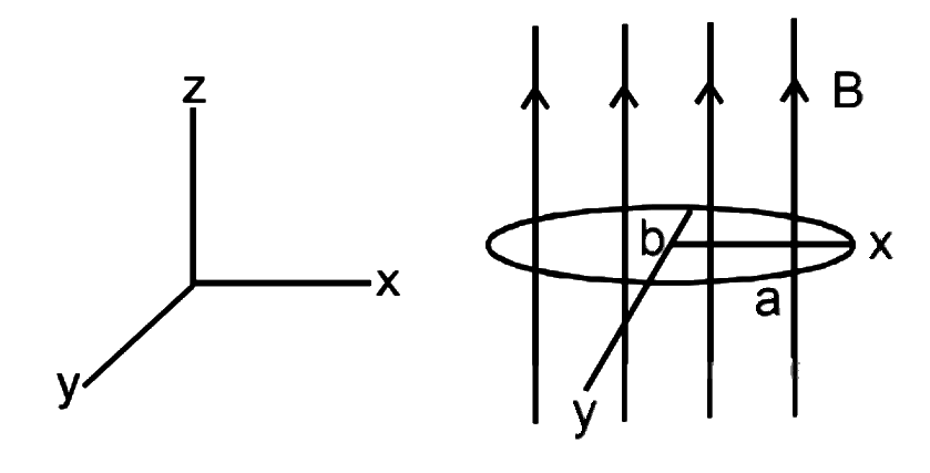
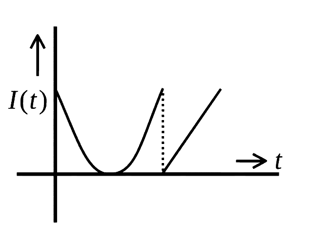
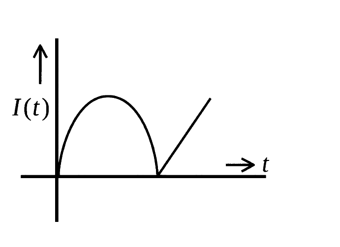
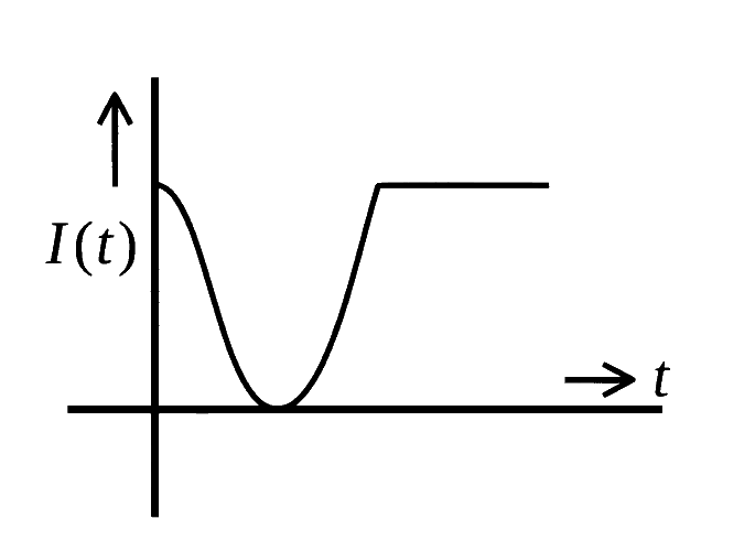
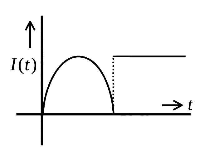
A conducting loop of finite resistance lies on the x−y plane. There is a constant magnetic field in the z direction. The area of the loop varies with time t, as A=A0(1+sint) in appropriate units. The figure that correctly indicates the qualitative behaviour of the power P dissipated in the loop as a function of time is:
Show answer and solution
Answer: (c)
Flux ϕ=BA=BA0(1+sint), so e=−dtdϕ=−BA0cost.
Power P=Re2=RB2A02cos2t.
At t=0, P is maximum; it falls to zero at t=π/2 and rises again (a cos2t curve).
Magnetic Flux & Faraday's Law · Power and heat in a loop
A conducting circular loop of area 1.0 m2 is placed perpendicular to a magnetic field which varies as B=sin(100t) Tesla. If the resistance of the loop is 100Ω, then the average thermal energy dissipated in the loop in one period is ______ J.
Show answer and solution
Answer: (c)
e=AdtdB=1×100cos(100t)=100cos(100t) V.
P=Re2=100104cos2(100t)=100cos2(100t), so Pavg=50 W.
Period T=1002π s.
Energy in one period =50×1002π=π J. So the answer is (c) π.
Magnetic Flux & Faraday's Law · Flux as a function of time
A circular loop of radius 20 cm and resistance 2Ω is placed in a time varying magnetic field B=(2t2+2t+3)T. At t=0, for the plane of the loop being perpendicular to the magnetic field and, the induced current in the loop at t=3 s is 50α A. The value of α is ______. (Take π=22/7)
Numerical answer type. Work it out, then open the answer.
Magnetic Flux & Faraday's Law · Power and heat in a loop
When a coil is placed in a time dependent magnetic field the power dissipated in it is P. The number of turns, area of the coil and radius of the coil wire are N,A and r respectively. For a second coil number of turns, area of the coil and radius of the coil wire are 2N,2A and 3r respectively. When the first coil is replaced with second coil the power dissipated in it is 2αP. The value of α is ______.
Magnetic Flux & Faraday's Law · Faraday's law and average emf
A coil of effective area 3 m2 is placed at right angles to a magnetic field of induction 0.05 Wb/m2 If the field is decreased to 20% of its original value in 10 second, the e.m.f. induced in the coil will be
Magnetic Flux & Faraday's Law · Faraday's law and average emf
A magnetic field 4×10⁻² T acts at right angles to a coil of area 100 cm2 with 50 turns. The average e.m.f. induced in the coil is 0.1 V, when it is removed from the field in time ' t '. The value of ' t ' is
Show answer and solution
Answer: (c)
Removing the coil takes flux from NBA to 0: e=tNBA.
A coil having ' N ' turns and resistance ' R ' Ω is connected to a galvanometer of resistance ' 6 R ' Ω. The magnetic flux linked with this coil changes from ϕ1 weber to ϕ2 weber in time ' t ' second. The induced current in the circuit is
A coil of ' n ' turns and resistance RΩ is connected in series with a resistance 2R. The combination is moved for time ' t ' second through magnetic flux ϕ1 to ϕ2. The induced current in the circuit is
A coil of n turns and resistance RΩ is connected in series with resistance R/4. The combination is moved for time t second through magnetic flux ϕ1 to ϕ2. The induced current in the circuit is
A coil of resistance 400Ω is placed in a magnetic field. If the magnetic flux ' ϕ ' ( Wb) linked with the coil varies with time ' t ' ( s) is ϕ=50t2+4, the current in the coil at t=2 s will be
Magnetic Flux & Faraday's Law · Faraday's law and average emf
The magnetic flux through a coil is 4×10⁻⁴ Wb at time t=0. It reduces to 30% of its original value in time t second. If e.m.f. induced in the coil is 0.56 mV then the value of t is
A coil of ' n ' turns and area ' A ' is suddenly removed from a magnetic field, a charge ' q ' flows through the coil. If resistance of the coil is ' R ' then the magnetic flux density is (in Wb/m2)
Show answer and solution
Answer: (b)
Removing the coil: flux changes from nBA to 0, so Δϕ=nBA.
Magnetic Flux & Faraday's Law · Faraday's law and average emf
A magnetic field of 2×10⁻² T acts at right angles to a coil of area 100 cm2 with 50 turns, The average e.m.f. induced in the coil is 0.1 V, when it is removed from the field in time t. The value of ' t ' is (in second)
A coil of resistance 250Ω is placed in a magnetic field. If the magnetic flux (ϕ) linked with the coil varies with time t(s) as ϕ=50t2+7. The current in the coil at t=4 s is
The magnetic flux ϕ (in weber) linked with a closed circuit of resistance 8Ω varies with time (in seconds) as ϕ=5t2−36t+1. The induced current in the circuit at t=2 s is __________ A.
Numerical answer type. Work it out, then open the answer.
Show answer and solution
Answer: 2
dtdϕ=10t−36; at t=2 s, dtdϕ=20−36=−16 Wb/s, so ∣e∣=16 V
The magnetic flux through a coil of resistance ' R ' changes by an amount ' Δϕ ' in time ' Δt '. The amount of induced current and induced charge in the coil are respectively
Magnetic Flux & Faraday's Law · Faraday's law and average emf
A coil is placed perpendicular to a magnetic field of 5000 T. When the field is changed to 3000 T in 2 s, an induced emf of 22 V is produced in the coil. If the diameter of the coil is 0.02 m, then the number of turns in the coil is:
Magnetic Flux & Faraday's Law · Faraday's law and average emf
A rectangular loop of length 2.5 m and width 2 m is placed at 60∘ to a magnetic field of 4 T. The loop is removed from the field in 10 sec. The average emf induced in the loop during this time is
Show answer and solution
Answer: (c)
Taking 60∘ as the angle between B and the normal: ϕ=BAcos60∘.
ϕ=4×(2.5×2)×21=10 Wb, and it falls to 0 when the loop is removed.
Magnetic Flux & Faraday's Law · Faraday's law and average emf
A square loop of side 10 cm and resistance 0.7Ω is placed vertically in east-west plane. A uniform magnetic field of 0.20 T is set up across the plane in north east direction. The magnetic field is decreased to zero in 1 s at a steady rate. Then, magnitude of induced emf is x×10−3 V. The value of x is __________.
Numerical answer type. Work it out, then open the answer.
Show answer and solution
Answer: 2
Loop in the east-west vertical plane, so its normal points north-south.
Field along north-east makes 45∘ with the normal: ϕ=BAcos45∘=0.2×0.01×21=2×10⁻³ Wb.
Flux falls to zero steadily in 1 s: e=12×10−3=2×10⁻³ V.
A coil is placed in magnetic field such that plane of coil is perpendicular to the direction of magnetic field. The magnetic flux through a coil can be changed:
A. By changing the magnitude of the magnetic field within the coil.
B. By changing the area of coil within the magnetic field.
C. By changing the angle between the direction of magnetic field and the plane of the coil. D. By reversing the magnetic field direction abruptly without changing its magnitude. Choose the most appropriate answer from the options given below:
Show answer and solution
Answer: (b)
Φ=BAcosθ, so flux changes if B, A or θ changes.
A: changing B changes Φ. B: changing A changes Φ. C: changing the angle changes cosθ.
D: reversing B takes Φ from +BA to −BA; the magnitude of Φ is unchanged, which is why the official answer leaves it out.
Magnetic Flux & Faraday's Law · Faraday's law and average emf
A coil having effective area A, is held with its plane normal to magnetic field of induction B. The magnetic induction is quickly reduced by 25% of its initial value in 2 second. Then the e.m.f. induced across the coil will be
Magnetic Flux & Faraday's Law · Faraday's law and average emf
A magnetic field of 2×10⁻² T acts at right angles to a coil of area 100 cm2 with 50 turns. The average e.m.f. induced in the coil is 0.1 V, when it is removed from the field in time 't'. The value of 't' is
Magnetic Flux & Faraday's Law · Faraday's law and average emf
A coil having effective area 'A' is held with its plane normal to a magnitude field of induction 'B'. The magnetic induction is quickly reduced to 25% of its initial value in 1 second. The e.m.f. induced in the coil (in volt) will be
Magnetic Flux & Faraday's Law · Faraday's law and average emf
A conducting circular loop of radius π10 cm is placed perpendicular to a uniform magnetic field of 0.5 T. The magnetic field is decreased to zero in 0.5 s at a steady rate. The induced emf in the circular loop at 0.25 s is:
Show answer and solution
Answer: (a)
A=π(π10)2=100 cm2=10−2 m2
Steady rate, so emf is the same at every instant: e=AΔtΔB=10−2×0.50.5
The magnetic flux through a circuit of resistance 'R' changes by an amount Δϕ in the time Δt. The total quantity of electric charge 'Q' which passes during this time through any point of the circuit is
Magnetic Flux & Faraday's Law · Faraday's law and average emf
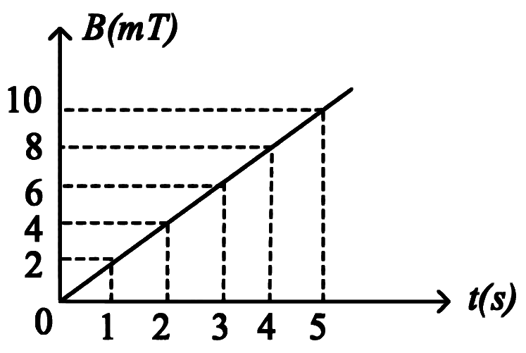
The magnetic field B crossing normally a square metallic plate of area 4 m2 is changing with time as shown in figure. The magnitude of induced emf in the plate during t=2 s to t=4 s, is __________ mV.
Numerical answer type. Work it out, then open the answer.
Show answer and solution
Answer: 8
From the graph, B rises uniformly: dtdB=4−28−4=2 mT/s.
Magnetic Flux & Faraday's Law · Flux as a function of time
The magnetic flux through a loop of resistance 10Ω varying according to the relation ϕ=6t2+7t+1, where ϕ is in milliweber, time is in second at time t=1 s the induced e.m.f. is
Magnetic Flux & Faraday's Law · Changing area of a loop
A conducting circular loop is placed in a uniform magnetic field of 0.4 T with its plane perpendicular to the field. Somehow, the radius of the loop starts expanding at a constant rate of 1 mm/s. The magnitude of induced emf in the loop at an instant when the radius of the loop is 2 cm will be ___________ μV.
Numerical answer type. Work it out, then open the answer.
Magnetic Flux & Faraday's Law · Changing area of a loop
A certain elastic conducting material is stretched into a circular loop. It is placed with its plane perpendicular to a uniform magnetic field B = 0.8 T. When released the radius of the loop starts shrinking at a constant rate of 2 cms −1. The induced emf in the loop at an instant when the radius of the loop is 10 cm will be __________ mV.
Numerical answer type. Work it out, then open the answer.
An insulated copper wire of 100 turns is wrapped around a wooden cylindrical core of the cross- sectional area 24 cm2. The two ends of the wire are connected to a resistor. The total resistance in the circuit is 12Ω. If an externally applied uniform magnetic field in the core along its axis changes from 1.5 T in one direction to 1.5 T in the opposite direction, the charge flowing through a point in the circuit during the change of magnetic field will be ___________ mC.
Numerical answer type. Work it out, then open the answer.
Show answer and solution
Answer: 60
Field reverses, so ΔB=3 T and Δϕ=NAΔB=100×24×10−4×3=0.72 Wb.
A square loop of side 1 m and resistance 1 Ω is placed in a magnetic field of 0.5 T. If the plane of loop is perpendicular to the direction of magnetic field, the magnetic flux through the loop is
Show answer and solution
Answer: (b)
Plane perpendicular to B means the normal is along B, so Φ=BA.
A=1×1=1 m2, Φ=0.5×1=0.5 Wb (resistance is not needed).
The magnetic flux through a coil perpendicular to its plane is varying according to the relation ϕ=(5t3+4t2+2t−5) Weber. If the resistance of the coil is 5 ohm, then the induced current through the coil at t = 2 s will be,
Magnetic flux (in weber) in a closed circuit of resistance 20 Ω varies with time t(s) at ϕ = 8t2 − 9t + 5. The magnitude of the induced current at t = 0.25 s will be ____________ mA.
Numerical answer type. Work it out, then open the answer.
Magnetic Flux & Faraday's Law · Flux as a function of time
A conducting circular loop is placed in X−Y plane in presence of magnetic field B=(3t3j^+3t2k^) in SI unit. If the radius of the loop is 1 m, the induced emf in the loop, at time, t=2 s is nπ V. The value of n is ___________.
Numerical answer type. Work it out, then open the answer.
Show answer and solution
Answer: 12
Loop in the XY plane: area vector along k^, so only Bz=3t2 gives flux.
Magnetic Flux & Faraday's Law · Power and heat in a loop
A coil is placed in a time varying magnetic field. If the number of turns in the coil were to be halved and the radius of wire doubled, the electrical power dissipated due to the current induced in the coil would be:
(Assume the coil to be short circuited.)
Show answer and solution
Answer: (d)
e∝N (same coil area, same dB/dt).
Wire length ∝N, so R=πr2ρL∝r2N.
P=Re2∝NN2r2=Nr2.
N→N/2, r→2r: P′=21×4P=2P. So the answer is (d) Doubled.
Magnetic Flux & Faraday's Law · Power and heat in a loop
In a coil of resistance 8Ω, the magnetic flux due to an external magnetic field varies with time as ϕ=32(9−t2). The value of total heat produced in the coil, till the flux becomes zero, will be _____________ J.
Numerical answer type. Work it out, then open the answer.
Show answer and solution
Answer: 2
e=−dtdϕ=34t; flux becomes zero when 9−t2=0, i.e. t=3 s.
At what rate a single conductor should cut the magnetic flux so that current of 1.5 mA flows through it when a resistance of 5Ω is connected across its ends?
the magnetic flux (in weber) in a closed circuit of resistance 20Ω varies with time t second according to equation ϕ=5t2−6t+9. The magnitude of induced current at t=0.2 second is
Show answer and solution
Answer: (c)
dtdϕ=10t−6; at t=0.2 s, dtdϕ=2−6=−4 Wb/s, so ∣e∣=4 V
Magnetic Flux & Faraday's Law · Faraday's law and average emf
A coil has an area 0.06 m2 and it has 600 turns. After placing the coil in a magnetic field of strength 5×10⁻⁵ Wb m−2, it is rotated through 90∘ in 0.2 second. The magnitude of average e.m.f induced in the coil is
[cos0∘=sin90∘=1 and sin0∘=cos90∘=0]
Show answer and solution
Answer: (d)
Rotating through 90∘ from the perpendicular position: flux goes from NBA to 0, so Δϕ=NBA.
Magnetic Flux & Faraday's Law · Flux as a function of time
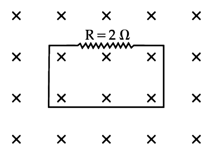
In the given figure the magnetic flux through the loop increases according to the relation ϕB(t) = 10t2 + 20t, where ϕB is in milliwebers and t is in seconds.
The magnitude of current through R = 2Ω resistor at t = 5 s is ___________ mA.
Numerical answer type. Work it out, then open the answer.
Magnetic Flux & Faraday's Law · Power and heat in a loop
A circular conducting coil of radius 1 m is being heated by the change of magnetic field Bpassing perpendicular to the plane in which the coil is laid. The resistance of the coil is 2 μΩ. The magnetic field is slowly switched off such that its magnitude changes in time as
B=π4×10⁻³T(1−100t)
The energy dissipated by the coil before the magnetic field is switched off completely is E = ___________ mJ.
Numerical answer type. Work it out, then open the answer.
Magnetic Flux & Faraday's Law · Faraday's law and average emf
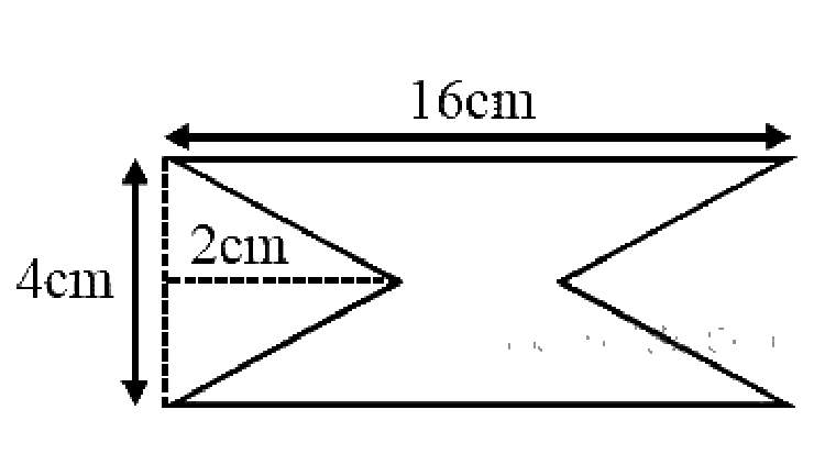
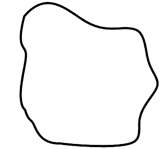
At time t = 0 magnetic field of 1000 Gauss is passing perpendicularly through the area defined by the closed loop shown in the figure. If the magnetic field reduces linearly to 500 Gauss, in the next 5s, then induced EMF in the loop is:
Show answer and solution
Answer: (c)
Loop area = rectangle minus the two triangular cut-outs (base 4 cm, height 2 cm each).
A coil of n turns and resistance RΩ is connected in series with a resistance 2R. The combination is moved for time t second through magnetic flux ϕ1 to ϕ2. The induced current in the circuit is
Consider a circular coil of wire carrying constant current I, forming a magnetic dipole. The magnetic flux through an infinite plane that contains the circular coil and excluding the circular coil area is given by ϕi. The magnetic flux through the area of the circular coil area is given by ϕ0. Which of the following option is correct?
Show answer and solution
Answer: (d)
Magnetic field lines form closed loops, so the net flux through the whole infinite plane is zero.
Lines going up through the coil area (ϕ0) return down through the plane outside the coil (ϕi).
A uniform magnetic field B exists in a direction perpendicular to the plane of a square loop made of a metal wire. The wire has a diameter of 4 mm and a total length of 30 cm. The magnetic field changes with time at a steady rate dtdB = 0.032 Ts–1. The induced current in the loop is close to (Resistivity of the metal wire is 1.23 × 10⁻⁸ Ωm)
Show answer and solution
Answer: (d)
Square side =430=7.5 cm, area A=(0.075)2=5.625×10⁻³ m2.
A loop ABCDEFA of straight edges has six corner points A(0, 0, 0), B(5, 0, 0), C(5, 5, 0), D (0, 5, 0), E(0, 5, 5) and F(0, 0, 5). The magnetic field in this region is B=(3i^+4k^)T. The quantity of flux through the loop ABCDEFA (in Wb) is _______.
Numerical answer type. Work it out, then open the answer.
Show answer and solution
Answer: 175
Split the loop into two squares: ABCD in the z=0 plane and ADEF in the x=0 plane, each of area 25 m2.
Going A→B→C→D, the area vector of ABCD is 25k^; going D→E→F→A, the area vector of ADEF is 25i^.
Magnetic Flux & Faraday's Law · Faraday's law and average emf
A 800 turn coil of effective area 0.05 m2 is kept perpendicular to a magnetic field 5 × 10⁻⁵ T. When the plane of the coil is rotated by 90° around any of its coplanar axis in 0.1 s, the emf induced in the coil will be:
Show answer and solution
Answer: (b)
Rotating by 90∘: flux goes from NBA to 0, so Δϕ=NBA.
A conducting circular loop made of a thin wire, has area 3.5 × 10⁻³ m2 and resistance 10 Ω. It is placed perpendicular to a time dependent magnetic field B(t) = (0.4T)sin(50πt). The field is uniform in space. Then the net charge flowing through the loop during t = 0 s and t = 10 ms is close to:
Show answer and solution
Answer: (a)
At t=0: B=0. At t=10 ms: B=0.4sin(50π×0.01)=0.4sin2π=0.4 T.
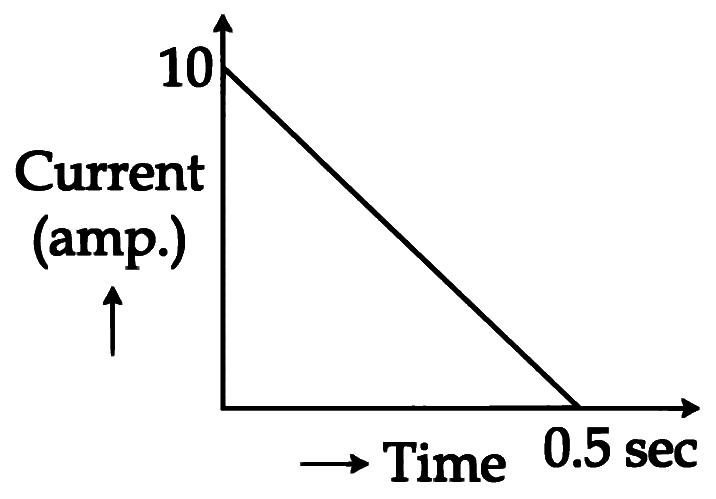
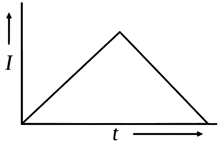
In a coil of resistance 100 Ω, a current is induced by changing the magnetic flux through it as shown in the figure. The magnitude of change in flux through the coil is:
Show answer and solution
Answer: (d)
Charge q = area under the I–t graph =21×10×0.5=2.5 C.
A long solenoid of diameter 0.1 m has 2 × 10⁴ turns per meter. At the centre of the solenoid, a coil of 100 turns and radius 0.01 m is placed with its axis coinciding with the solenoid axis. The current in the solenoid reduces at a constant rate to 0 A from 4 A in 0.05 s. If the resistance of the coil is 10 π2 Ω, the total charge flowing through the coil during this time is
Show answer and solution
Answer: (b)
Solenoid field B=μ0nI=4π×10−7×2×104×4=32π×10−3 T.
Flux through the coil: ϕ=NBπr2=100×32π×10−3×π×10−4=32π2×10⁻⁵ Wb; it falls to 0.
Magnetic Flux & Faraday's Law · Power and heat in a loop
A conducting metal circular-wire-loop of radius r is placed perpendicular to a magnetic field which varies with time as
B = B0eτ−t, where B0 and τ are constants, at time t = 0. If the resistance of the loop is R then the heat generated in the loop after a long time (t →∞) is:
Magnetic Flux & Faraday's Law · Faraday's law and average emf
A coil of circular cross-section having 1000 turns and 4 cm2 face area is placed with its axis parallel to a magnetic field which decreases by 10−2 Wb m−2 in 0.01 s. The e.m.f. induced in the coil is:
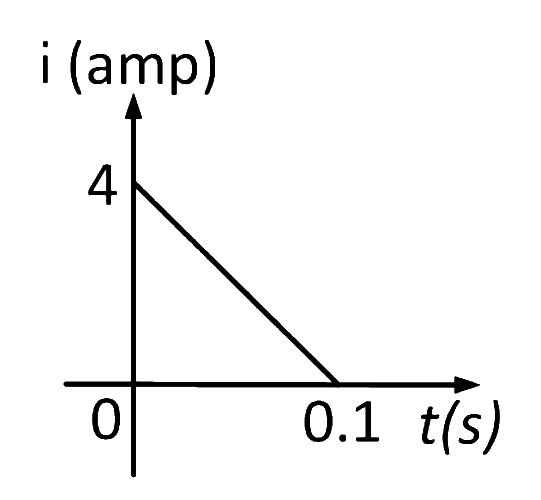
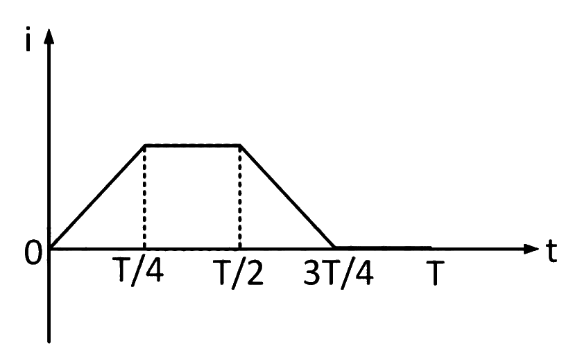
In a coil of resistance 10 Ω, the induced current developed by changing magnetic flux through it, is shown in figure as a function of time. The magnitude of change in flux through the coil in weber is
Show answer and solution
Answer: (b)
Charge q = area under the i–t graph =21×4×0.1=0.2 C.
Magnetic Flux & Faraday's Law · Changing area of a loop
A conducting circular loop is placed in a uniform magnetic field, B = 0.025 T with its plane perpendicular to the loop. The radius of the loop is made to shrink at a constant rate of 1 mm s−1. The induced emf when the radius is 2 cm, is
Show answer and solution
Answer: (b)
Field is perpendicular to the plane of the loop: ϕ=Bπr2⇒e=B⋅2πrdtdr
Magnetic Flux & Faraday's Law · Changing area of a loop
A conducting circular loop is placed in a uniform magnetic field 0.04 T with its plane perpendicular to the magnetic field. The radius of the loop starts shrinking at 2 mm/s. The induced emf in the loop when the radius is 2 cm is
A circular disc of radius 0.2 meter is placed in a uniform magnetic field of induction π1(m2Wb) in such a way that its axis makes an angle of 60° with B. The magnetic flux linked with the disc is
Show answer and solution
Answer: (c)
Φ=BAcosθ with θ=60∘ between B and the disc's axis.
A coil having n turns and resistance RΩ is connected with a galvanometer of resistance 4RΩ. This combination is moved in time t seconds from a magnetic field W1 weber to W2 weber. The induced current in the circuit is
The magnetic flux through a circuit of resistance R changes by an amount Δϕ in a time Δt. Then the total quantity of electric charge Q that passes any point in the circuit during the time Δt is represented by
A rectangular coil of 20 turns and area of cross-section 25 sq. cm has a resistance of 100Ω. If a magnetic field which is perpendicular to the plane of coil changes at a rate of 1000 tesla per second, the current in the coil is
Magnetic Flux & Faraday's Law · Faraday's law and average emf
A magnetic field of 2×10⁻² T acts at right angles to a coil of area 100 cm2, with 50 turns. The average e.m.f. induced in the coil is 0.1 V, when it is removed from the field in t sec. The value of t is
Lenz's Law, Eddy Currents & Induced Electric Field · Magnet falling through a ring or pipe
Spherical insulating ball and a spherical metallic ball of same size and mass are dropped from the same height. Choose the correct statement out of the following {Assume negligible air friction}
Show answer and solution
Answer: (c)
The only magnetic field present is the Earth's field, which is practically uniform over the ball's path.
The flux through any part of the metal ball hardly changes, so eddy currents (and their drag) are negligible.
Both balls fall with acceleration g from the same height.
So both reach the ground simultaneously, answer (c).
Lenz's Law, Eddy Currents & Induced Electric Field · Lenz's law and direction of current
Three identical coils C1,C2 and C3 are closely placed such that they share a common axis. C2 is exactly midway. C1 carries current I in anti-clockwise direction while C3 carries current I in clockwise direction. An induced current flows through C2 will be in clockwise direction when
Show answer and solution
Answer: (b)
Viewed from one side, anticlockwise I in C1 gives a field towards the viewer at C2; clockwise I in C3 gives a field away from the viewer. At the midpoint they cancel.
(a) and (c): both changes are equal and opposite, so no net flux change and no current.
(b): C1 approaching increases the 'towards viewer' flux and C3 receding reduces the 'away' flux; both increase net flux towards the viewer.
Induced current in C2 must give a field away from the viewer, i.e. clockwise. Answer (b).
Lenz's Law, Eddy Currents & Induced Electric Field · Magnet falling through a ring or pipe
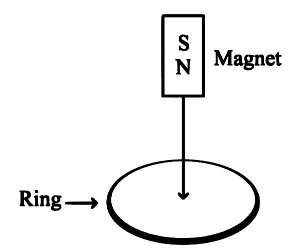
A copper ring having a cut such as not to form a complete loop is held horizontally and a bar magnet is dropped through the ring with its length along the axis of the ring as shown in figure. The acceleration of the falling magnet is ( g= acceleration due to gravity)
Show answer and solution
Answer: (a)
The ring has a cut, so it is not a closed loop.
An emf is induced but no current can flow, so there is no opposing magnetic force on the magnet.
The magnet falls freely, acceleration =g. Answer (a).
Lenz's Law, Eddy Currents & Induced Electric Field · Magnet falling through a ring or pipe
A copper ring is held horizontally and a bar magnet is dropped through the ring with its length along the axis of the ring. The acceleration of the falling magnet while it is passing through the ring is
Show answer and solution
Answer: (b)
The magnet's flux through the closed ring changes as it falls, inducing a current.
By Lenz's law the induced current opposes the motion (repels while approaching, attracts while leaving).
So the magnet's acceleration is less than g, answer (b).
Lenz's Law, Eddy Currents & Induced Electric Field · Lenz's law and direction of current
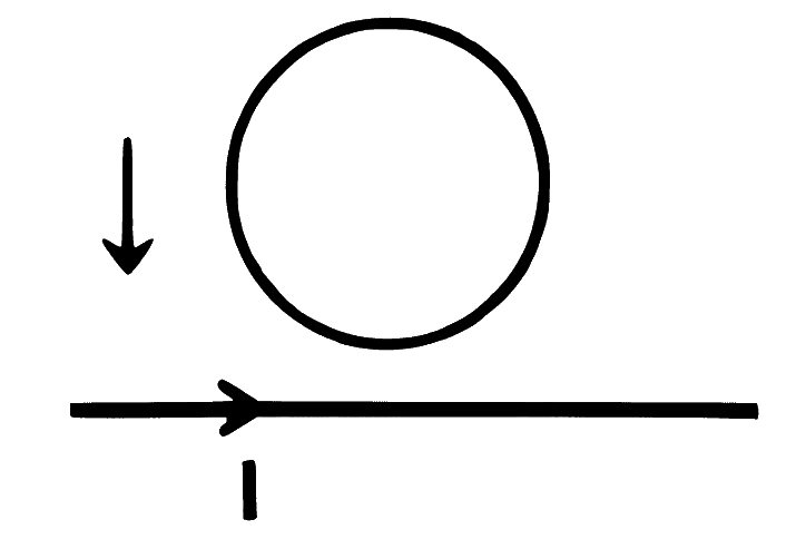
A conducting ring of certain resistance is falling towards a current carrying straight long conductor. The ring and conductor are in the same plane. Then
Show answer and solution
Answer: (c)
Above a wire carrying current to the right, the field is out of the page.
As the ring falls towards the wire, the field and hence the outward flux increase.
The induced current must give an into-the-page field, so it is clockwise.
Lenz's Law, Eddy Currents & Induced Electric Field · Magnet falling through a ring or pipe
A hollow metal pipe is held vertically and bar magnet is dropped through it with its length along the axis of the pipe. The acceleration of the falling magnet is ( g= acceleration due to gravity)
Show answer and solution
Answer: (b)
The moving magnet induces eddy currents in the metal pipe.
By Lenz's law these oppose the fall, giving an upward retarding force.
Lenz's Law, Eddy Currents & Induced Electric Field · Magnet falling through a ring or pipe
Spherical insulating ball and a spherical metallic ball of same size and mass are dropped from the same height. Choose the correct statement out of the following
{Assume negligible air friction}
Show answer and solution
Answer: (c)
The metal ball moves through the Earth's magnetic field, so small eddy currents can be induced in it.
By Lenz's law these oppose its motion, slightly reducing its acceleration.
The insulating ball has no eddy currents and falls with g.
So the insulating ball reaches earlier, answer (c).
Lenz's Law, Eddy Currents & Induced Electric Field · Lenz's law and direction of current
The magnet is moved towards the coil with speed 'V'. The induced e.m.f. in the coil is 'e'. The magnet and the coil move away from one another each moving with speed 'V'. The induced e.m.f. in the coil is
Show answer and solution
Answer: (b)
Induced emf depends on the rate of flux change, i.e. on the relative speed of magnet and coil.
First case: relative speed V gives emf e.
Second case: each moves away with V, relative speed 2V, so emf =2e (opposite sign).
Lenz's Law, Eddy Currents & Induced Electric Field · Magnet falling through a ring or pipe
Given below are two statements: one is labelled as Assertion A and the other is labelled as Reason R
Assertion A: A bar magnet dropped through a metallic cylindrical pipe takes more time to come down compared to a non-magnetic bar with same geometry and mass.
Reason R: For the magnetic bar, Eddy currents are produced in the metallic pipe which oppose the motion of the magnetic bar.
In the light of the above statements, choose the correct answer from the options given below
Show answer and solution
Answer: (d)
A falling magnet changes the flux through the metal pipe, inducing eddy currents (R is true).
By Lenz's law these currents oppose the magnet's motion, so it falls more slowly than a non-magnetic bar, which induces no currents (A is true).
Lenz's Law, Eddy Currents & Induced Electric Field · Lenz's law and direction of current
Two conducting wire loops are concentric and lie in the same plane. The current in the outer loop is clockwise and increasing with time. The induced current in the inner loop is
Show answer and solution
Answer: (b)
Clockwise current in the outer loop gives an inward (into the plane) field inside it.
This inward flux through the inner loop increases with time.
The induced current must give an outward field, so it is anticlockwise.
Lenz's Law, Eddy Currents & Induced Electric Field · Lenz's law and direction of current
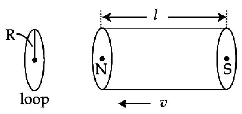
A bar magnet is passing through a conducting loop of radius R with velocity v. The radius of the bar magnet is such that it just passes through the loop. The induced e.m.f. in the loop can be represented by the approximate curve:
Show answer and solution
Answer: (c)
As the N end approaches and passes the loop, flux increases quickly, giving a sharp emf pulse.
As the S end leaves, the flux decreases, giving a pulse of the opposite sign.
While the uniform middle part passes, flux hardly changes, so emf is nearly zero; the pulses are l/v apart.
So the curve has two opposite pulses separated by l/v; with the chosen sign convention this is (c).
Lenz's Law, Eddy Currents & Induced Electric Field · Lenz's law and direction of current
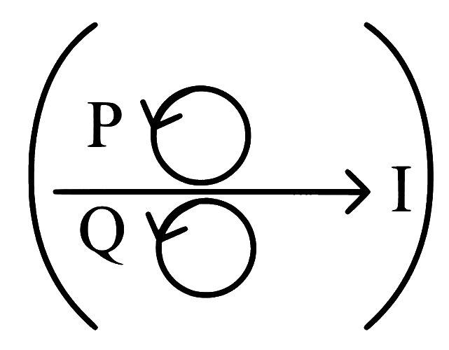
Metal rings P and Q are lying in the same plane, where current I is increasing steadily. The induced current in metal rings is shown correctly in figure
Show answer and solution
Answer: (c)
Above the wire (ring P) the field is out of the page; below (ring Q) it is into the page. Both grow as I increases.
P: outward flux increasing, so induced current gives an inward field, i.e. clockwise.
Q: inward flux increasing, so induced current gives an outward field, i.e. anticlockwise.
Figure (c) shows P clockwise and Q anticlockwise. Answer (c).
Lenz's Law, Eddy Currents & Induced Electric Field · Lenz's law and direction of current
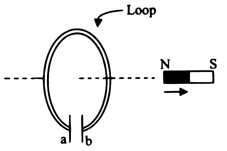
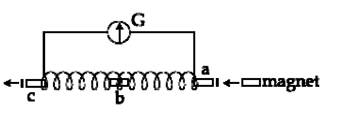
A small bar magnet is moved through a coil at constant speed from one end to the other. Which of the following series of observations will be seen on the galvanometer G attached across the coil?
Three positions shown describe:
(a) the magnet's entry
(b) magnet is completely inside and
(c) magnet's exit.
Show answer and solution
Answer: (c)
Entry: flux through the coil increases, so G deflects one way.
Fully inside (small magnet in a long coil): flux nearly constant, so no deflection.
Exit: flux decreases, so G deflects the opposite way.
This matches (c): deflection, zero, opposite deflection.
Lenz's Law, Eddy Currents & Induced Electric Field · Lenz's law and direction of current
A long solenoid of radius R carries a time (t) - dependent current
I(t)=I0t(1 - t). A ring of radius 2R is placed coaxially near its middle. During the time interval 0 ≤ t ≤ 1, the induced current (IR) and the induced EMF(VR) in the ring change as:
Show answer and solution
Answer: (d)
Flux through the ring comes only from inside the solenoid: ϕ=μ0nIπR2∝I.
VR∝dtdI=I0(1−2t).
At t=0.5: dtdI=0, so VR=0; for t<0.5 it is positive, for t>0.5 negative, so IR reverses.
So the answer is (d) at t=0.5 the direction of IR reverses and VR is zero.
Lenz's Law, Eddy Currents & Induced Electric Field · Lenz's law and direction of current
A very long solenoid of radius R is carrying current I(t) = kte–at(k > 0), as a function of time (t ≥ 0). counter clockwise current is taken to be positive. A circular conducting coil of radius 2R is placed in the equatorial plane of the solenoid and concentric with the solenoid. The current induced in the outer coil is correctly depicted, as a function of time, by :-
Show answer and solution
Answer: (a)
Induced current in the coil ∝−dtdI (Lenz's law), since the flux ∝I.
dtdI=ke−at(1−at): equal to k (non-zero) at t=0, zero at t=a1, negative after that and tending to zero.
So the induced current starts negative (non-zero), crosses zero at t=1/a, becomes positive, peaks and decays to zero.
Lenz's Law, Eddy Currents & Induced Electric Field · Induced electric field
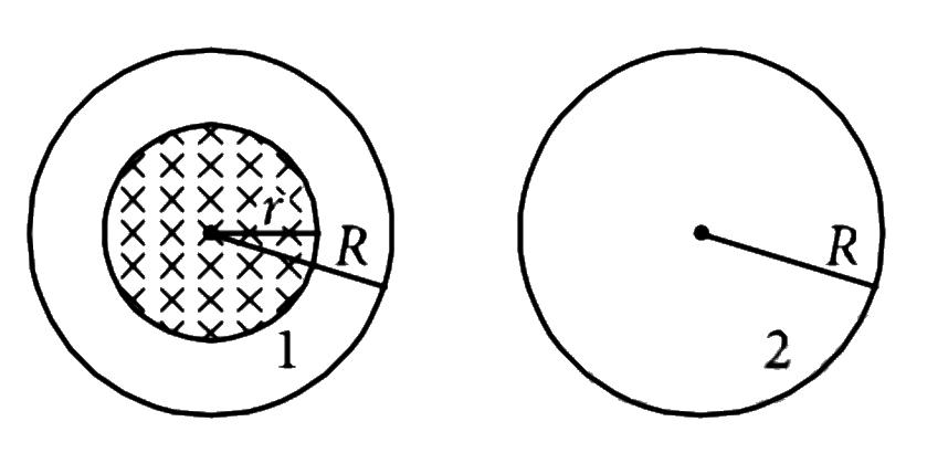
A uniform magnetic field is restricted within a region of radius r. The magnetic field changes with time at a rate dtdB. Loop 1 of radius R > r encloses the region r and loop 2 of radius R is outside the region of magnetic field as shown in the figure. Then the e.m.f. generated is
Show answer and solution
Answer: (d)
Induced emf =−dtdϕ, and flux counts only the area where B exists.
Loop 1 encloses the whole field region of area πr2 (not πR2): ϕ1=Bπr2⇒ε1=−dtdBπr2.
Loop 2 encloses no field: ϕ2=0⇒ε2=0.
So the answer is (d) −dtdBπr2 in loop 1 and zero in loop 2.
Lenz's Law, Eddy Currents & Induced Electric Field · Lenz's law and direction of current
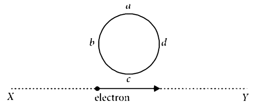
An electron moves on a straight line path XY as shown. The abcd is a coil adjacent to the path of electron. What will be the direction of current, if any, induced in the coil?
Show answer and solution
Answer: (a)
A moving electron is a current (opposite to its motion), so it sets up a magnetic field through the coil.
As the electron approaches, the flux through the coil increases; after it passes, the flux decreases.
By Lenz's law the induced current has one direction while flux increases and the opposite while it decreases.
So the current reverses as the electron goes past, answer (a).
Lenz's Law, Eddy Currents & Induced Electric Field · Induced electric field
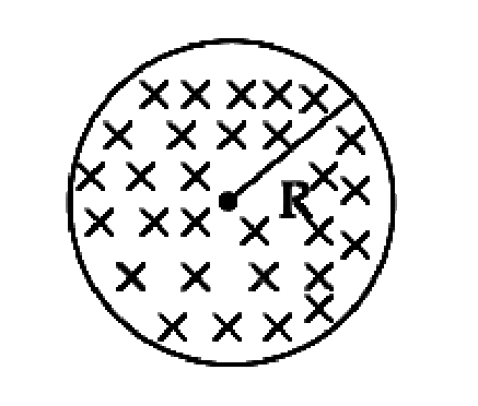
Figure shows a circular area of radius R where a uniform magnetic field Bis going into the plane of paper and increasing in magnitude at a constant rate. In that case, which of the following graphs, drawn schematically, correctly shows the variation of the induced electric field E(r)?
Show answer and solution
Answer: (a)
Use ∮E⋅dl=dtdϕ on a circle of radius r.
Inside (r<R): E2πr=πr2dtdB⇒E=2rdtdB, linear in r.
Outside (r>R): E2πr=πR2dtdB⇒E=2rR2dtdB, falls as r1.
Straight rise to a peak at r=R, then a 1/r decay. So the answer is (a).
Lenz's Law, Eddy Currents & Induced Electric Field · Eddy currents
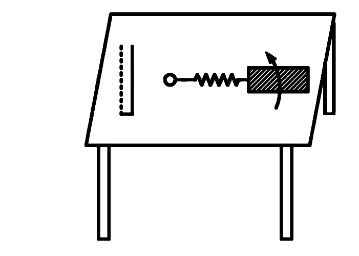
A coil is suspended in a uniform magnetic field, with the plane of the coil parallel to the magnetic lines of force. When a current is passed through the coil it starts oscillating; It is very difficult to stop. But if an aluminium plate is placed near to the coil, it stops. This is due to:
Show answer and solution
Answer: (d)
The oscillating coil changes the magnetic flux through the nearby aluminium plate.
Eddy currents are induced in the plate; by Lenz's law they oppose the coil's motion.
This electromagnetic damping stops the coil. Answer (d).
Lenz's Law, Eddy Currents & Induced Electric Field · Induced electric field
As a result of change in the magnetic flux linked to the closed loop as shown in the figure, an e.m.f. V volt is induced in the loop. The work done (joule) in taking a charge Q coulomb once along the loop is
Show answer and solution
Answer: (a)
Emf is the work done per unit charge in taking it once round the loop: ε=QW.
W=Qε=QV (the induced electric field is non-conservative, so the round-trip work is not zero).
Lenz's Law, Eddy Currents & Induced Electric Field · Magnet falling through a ring or pipe
A metal ring is held horizontally and bar magnet is dropped through the ring with its length along the axis of the ring. The acceleration of the falling magnet is
Show answer and solution
Answer: (c)
Induced current in the ring opposes the relative motion of the magnet (Lenz's law).
This gives an upward force on the magnet both while approaching and while leaving.
Lenz's Law, Eddy Currents & Induced Electric Field · Lenz's law and direction of current
Faraday's laws are consequence of conservation of
Show answer and solution
Answer: (a)
The direction of induced emf (Lenz's law, the minus sign in Faraday's law) ensures that work done against the induced current becomes electrical energy.
So Faraday's laws follow from conservation of energy, answer (a).
Motional EMF · Straight conductor and moving loops
A straight line conductor of length 0.4 m is moved with a speed of 7.0 ms−1 perpendicular to magnetic field of intensity 0.8 Wb m−2. The induced e.m.f. across the conductor is
Motional EMF · Straight conductor and moving loops
A rectangular wire loop of sides 8 cm and 3 cm with a small cut, is moving out of a region of uniform magnetic field of magnitude 0.3 T directed normal to the plane of the loop. The emf developed across the cut, if the velocity of the loop is 2 cm s−1, in a direction normal to the shorter side of the loop, will be:
Show answer and solution
Answer: (d)
Only the side perpendicular to the velocity cuts the field boundary: ε=Bℓv.
Velocity is normal to the shorter side, so ℓ=3 cm =0.03 m, v=0.02 m/s.
Motional EMF · Earth's field, aeroplane and falling wire
An aeroplane having a wing span of 30 m flies due north with the speed of 170 m/s. Magnetic field B=3.6×10⁻⁵ T. The potential difference between the tips of the wings will be
Show answer and solution
Answer: (b)
Horizontal wings cut the vertical component of the field: ε=Blv.
Motional EMF · Earth's field, aeroplane and falling wire
A 20 m long uniform copper wire held horizontally is allowed to fall under the gravity (g=10 m/s2) through a uniform horizontal magnetic field of 0.5 Gauss perpendicular to the length of the wire. The induced EMF across the wire when it travels a vertical distance of 200 m is ______ mV.
Show answer and solution
Answer: (c)
Speed after falling 200 m: v=2gh=2×10×200=2010 m/s.
Motional EMF · Force, power and work on a moving rod
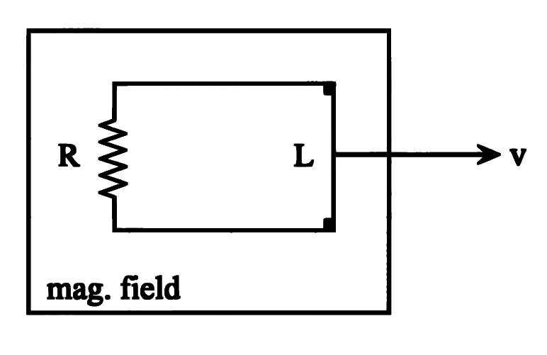
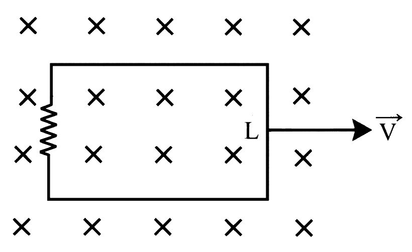
A long metal rod of length 'L' completes the circuit. The area of the coil is perpendicular to magnetic field 'B'. Total resistance of the circuit is 'R'. The force needed to move the rod in the direction as shown with constant speed 'V' is
Show answer and solution
Answer: (c)
Emf ε=BLV, current I=RBLV.
Magnetic force on the rod opposes motion: Fm=BIL=RB2L2V.
Constant speed needs an equal applied force: F=RB2L2V. So the answer is (c).
Motional EMF · Force, power and work on a moving rod
A metal rod of length 'L' completes the circuit as shown. The area of the circuit is perpendicular to magnetic field 'B'. Total resistance of the circuit is 'R'. The force needed to move the rod in the direction as shown with constant speed 'V' is
Show answer and solution
Answer: (b)
Emf ε=BLV, current I=RBLV.
Opposing magnetic force Fm=BIL=RB2L2V.
For constant speed, applied force F=RB2L2V. So the answer is (b).
Motional EMF · Force, power and work on a moving rod
A square loop of area 25 cm2 has a resistance of 10Ω. The loop is placed in uniform magnetic field of magnitude 40 T. The plane of the loop is perpendicular to the magnetic field. The work done in pulling the loop out of the magnetic field slowly and uniformly in one second will be
Show answer and solution
Answer: (b)
Side =25 cm =0.05 m; pulled out in 1 s, so v=0.05 m/s.
ε=Blv=40×0.05×0.05=0.1 V, I=100.1=0.01 A.
Work done = heat produced =εIt=0.1×0.01×1=1.0×10⁻³ J
Motional EMF · Force, power and work on a moving rod
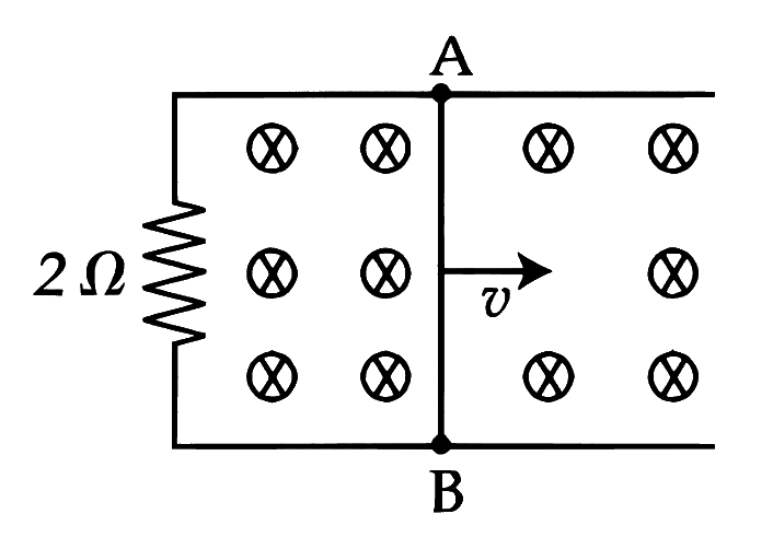
A 1 m long metal rod AB completes the circuit as shown in figure. The area of circuit is perpendicular to the magnetic field of 0.10 T. If the resistance of the total circuit is 2Ω then the force needed to move the rod towards right with constant speed (v) of 1.5 m/s is ______ N.
Show answer and solution
Answer: (b)
e=Blv=0.10×1×1.5=0.15 V
I=Re=20.15=0.075 A
Applied force balances the magnetic drag: F=BIl=0.10×0.075×1
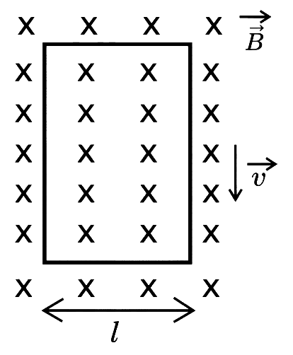
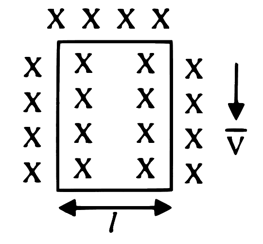
A long rectangular conducting loop of width 'l' mass 'm' and resistance 'R' is placed partly in a perpendicular magnetic field 'B'. With what velocity should it be pushed downwards so that it may continue to fall without any acceleration? (g = acceleration due to gravity)
Show answer and solution
Answer: (b)
Falling with speed v, the loop has emf e=Blv and current I=RBlv.
Magnetic force on the side of length l: F=BIl=RB2l2v, upward.
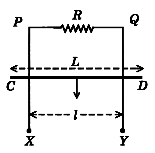
XPQY is a vertical smooth long loop having a total resistance R where PX is parallel to QY and separation between them is l. A constant magnetic field B perpendicular to the plane of the loop exists in the entire space. A rod CD of length L(L>l) and mass m is made to slide down from rest under the gravity as shown in figure. The terminal speed acquired by the rod is m/s. (g= acceleration due to gravity)
Show answer and solution
Answer: (a)
Only the part of rod between the rails (length l) is in the circuit, so e=Blv.
Motional EMF · Earth's field, aeroplane and falling wire
A simple pendulum made of mass 10 g and a metallic wire of length 10 cm is suspended vertically in a uniform magnetic field of 2 T. The magnetic field direction is perpendicular to the plane of oscillations of the pendulum. If the pendulum is released from an angle of 60∘ with vertical, then maximum induced EMF between the point of suspension and point of oscillation is ______ mV. (Take g=10 m/s2)
Numerical answer type. Work it out, then open the answer.
Show answer and solution
Answer: 100
Speed at the lowest point: v=2gl(1−cos60∘)=2×10×0.1×0.5=1 m/s
Maximum angular speed ω=lv=0.11=10 rad/s
Wire rotating about one end: e=21Bωl2=21×2×10×(0.1)2
Motional EMF · Straight conductor and moving loops
Initially a rectangular coil with length vertical is moving out with constant velocity ' v ' in a constant magnetic field ' B ' towards right. Now the same coil is rotated through 90∘ in same plane in same magnetic field B and the coil is moving with same velocity v. The magnitude of induced e.m.f. is now
Show answer and solution
Answer: (a)
Emf of a coil leaving the field: ε=Bℓv, where ℓ is the side perpendicular to v (the vertical side here).
Initially the length l (longer side) is vertical: ε1=Blv.
After rotating by 90∘ the breadth b (shorter side) is vertical: ε2=Bbv.
Since b<l, ε2<ε1. So the working gives (b) less than the initial emf.
Motional EMF · Straight conductor and moving loops
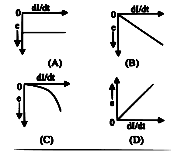
A rectangular metallic loop is moving out of a uniform magnetic field region to a field free region with a constant speed. When the loop is partially inside the magnetic field, the plot of magnitude of induced emf (ε) with time (t) is given by
Show answer and solution
Answer: (b)
While partly inside, the cutting edge length ℓ (side along the boundary) is fixed.
Flux decreases at a steady rate: ε=Bℓv= constant.
The ε–t graph is a horizontal line. So the answer is (b).
Motional EMF · Straight conductor and moving loops
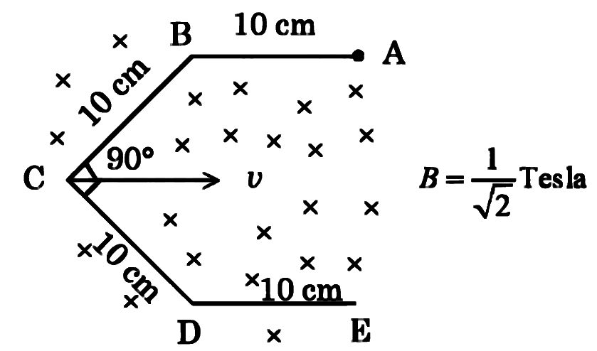
Conductor wire ABCDE with each arm 10 cm in length is placed in magnetic field of 21 Tesla, perpendicular to its plane. When conductor is pulled towards right with constant velocity of 10 cm/s, induced emf between points A and E is ________ mV.
Numerical answer type. Work it out, then open the answer.
Show answer and solution
Answer: 10
Emf between A and E equals that of the straight line AE, using its length perpendicular to v.
AB and DE are along v; BC and CD are at 45∘, each giving 10sin45∘=210 cm across.
Motional EMF · Earth's field, aeroplane and falling wire
A simple pendulum with bob of mass m and conducting wire of length L swings under gravity through an angle θ. The component of earth's magnetic field in the direction perpendicular to swing is B. Maximum e.m.f. induced across the pendulum is ( g= acceleration due to gravity)
Show answer and solution
Answer: (a)
Maximum speed at the lowest point: v=2gL(1−cosθ)=2gLsin2θ.
Motional EMF · Force, power and work on a moving rod
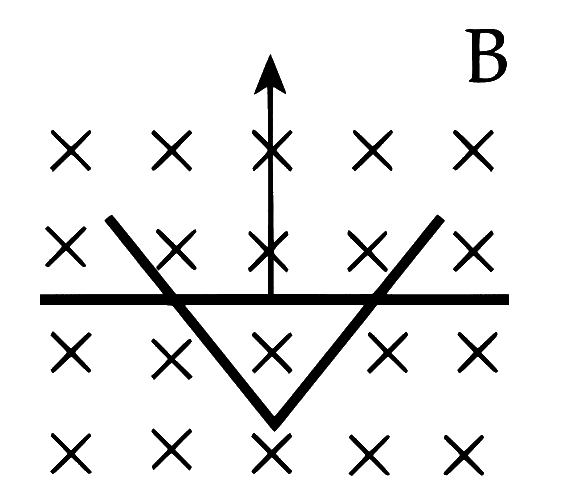
A conducting bar moves on two conducting rails as shown in the figure. A constant magnetic field B exists into the page. The bar starts to move from the vertex at time t = 0 with a constant velocity. If the induced EMF is E ∝ tn, then value of n is _________.
Numerical answer type. Work it out, then open the answer.
Show answer and solution
Answer: 1
Bar starts at the vertex and moves up with constant v, so its height is y=vt.
Length of bar between the rails l=2ytanα∝t (α = half-angle of the V).
A long rectangular conducting loop of width ' l ', mass ' m ' and resistance ' R ' is placed partly in a perpendicular magnetic field ' B '. It is pushed downwards with velocity ' V ' so that it may continue to fall freely. The velocity ' V ' is
Motional EMF · Earth's field, aeroplane and falling wire
A horizontal straight wire 5 m long extending from east to west is falling freely at right angle to horizontal component of earths magnetic field 0.60×10⁻⁴ Wb m−2. The instantaneous value of emf induced in the wire when its velocity is 10 ms−1 is _________ ×10−3 V.
Numerical answer type. Work it out, then open the answer.
Show answer and solution
Answer: 3
Wire (E–W), velocity (down) and BH (N) are mutually perpendicular, so ε=BHlv.
Motional EMF · Straight conductor and moving loops
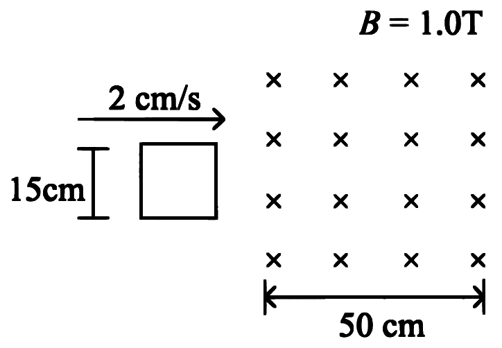
A square loop of side 15 cm is being moved towards right at a constant speed of 2 cm/s as shown in figure. The front edge enters the 50 cm wide magnetic field at t=0. The value of induced emf in the loop at t=10 s will be:
Show answer and solution
Answer: (a)
Distance moved in 10 s: 2×10=20 cm, so the front edge is 20 cm inside the field.
Back edge is 20−15=5 cm inside; the front edge is still within the 50 cm width.
The whole loop is in the field, so flux is constant and ε=0.
Motional EMF · Force, power and work on a moving rod
A square loop ABCD is moving with constant velocity ' v ' in a uniform magnetic field ' B ' which is perpendicular to the plane of paper and directed outward. The resistance of coil is ' R ', then the rate of production of heat energy in the loop is [ L - length of side of loop]
Show answer and solution
Answer: (b)
Only the side cutting the field edge gives motional emf e=BLv.
Motional EMF · Force, power and work on a moving rod
A square loop of area 25 cm2 has a resistance of 10Ω. The loop is placed in uniform magnetic field of magnitude 40 T. The plane of loop is perpendicular to the magnetic field. The work done in pulling the loop out of the magnetic field slowly and uniformly in 1 second, will be
Show answer and solution
Answer: (b)
Side L=25 cm2=5 cm=0.05 m; pulled out in 1 s, so v=0.05 m/s.
Motional EMF · Force, power and work on a moving rod
A rectangular loop of sides 12 cm and 5 cm, with its sides parallel to the x-axis and y-axis respectively, moves with a velocity of 5 cm/s in the positive x axis direction, in a space containing a variable magnetic field in the positive z direction. The field has a gradient of 10−3 T/cm along the negative x direction and it is decreasing with time at the rate of 10−3 T/s. If the resistance of the loop is 6 mΩ, the power dissipated by the loop as heat is __________ ×10−9 W.
Numerical answer type. Work it out, then open the answer.
Show answer and solution
Answer: 216
Rate of change of B seen by the moving loop: dtdB=∂t∂B+v∂x∂B
∂x∂B=−10−3 T/cm=−0.1 T/m, so dtdB=−10−3+0.05×(−0.1)=−6×10⁻³ T/s
Area A=0.12×0.05=6×10⁻³ m2, so e=AdtdB=3.6×10⁻⁵ V
Motional EMF · Straight conductor and moving loops
A conductor 10 cm long is moves with a speed 1 m/s perpendicular to a field of strength 1000 A/m. The emf induced in the conductor is (Given: μ0=4π×10−7 Wb/Am)
Show answer and solution
Answer: (c)
Field strength H is given, so B=μ0H=4π×10−7×1000=4π×10−4 T.
Motional EMF · Straight conductor and moving loops
A wire of length 1m moving with velocity 8 m/s at right angles to a magnetic field of 2T. The magnitude of induced emf, between the ends of wire will be __________.
Motional EMF · Earth's field, aeroplane and falling wire
An air craft of wing span 40 m flies horizontally in earth's magnetic field 5×10⁻⁵ T at a speed of 500 m/s. The e.m.f. generated between the tips of the wings of the air craft is
Show answer and solution
Answer: (b)
Emf between wing tips ε=Blv (with B the field component cutting the wings).
Motional EMF · Force, power and work on a moving rod
If current 'I' is flowing in the closed circuit with collective resistance 'R', the rate of production of heat energy in the loop as we pull it along with a constant speed 'V' is ( L= length of conductor, B= magnetic field)
Motional EMF · Straight conductor and moving loops
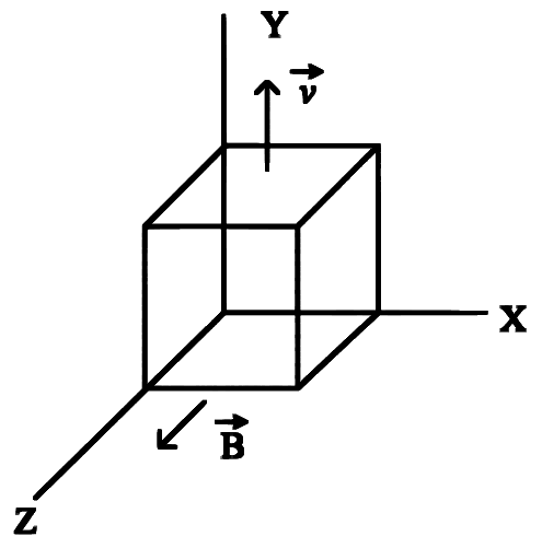
A metallic cube of side 15 cm moving along y-axis at a uniform velocity of 2 ms−1. In a region of uniform magnetic field of magnitude 0.5 T directed along z-axis. In equilibrium the potential difference between the faces of higher and lower potential developed because of the motion through the field will be _________ mV.
Numerical answer type. Work it out, then open the answer.
Show answer and solution
Answer: 150
v along y, B along z: qv×B is along x, so charges collect on the faces normal to x.
Motional EMF · Earth's field, aeroplane and falling wire
A conducting wire of length 2500 m is kept in east-west direction, at a height of 10 m from the ground. If it falls freely on the ground then the current induced in the wire is (Resistance of wire =252Ω, acceleration due to gravity g=10 m/s2,BH=2×10−5 T)
Show answer and solution
Answer: (b)
Speed on reaching the ground: v=2gh=2×10×10=102 m/s.
Motional EMF · Force, power and work on a moving rod
A square loop of area 25 cm2 has a resistance of 10Ω. This loop is placed in a uniform magnetic field of magnitude 40 T. The plane of loop is perpendicular to the magnetic field. The work done in pulling the loop out of the magnetic field slowly and uniformly in one second, will be
Motional EMF · Force, power and work on a moving rod
A square loop of area 25 cm2 has a resistance of 10 Ω. The loop is placed in uniform magnetic field of magnitude 40.0 T. The plane of loop is perpendicular to the magnetic field. The work done in pulling the loop out of the magnetic field slowly and uniformly in 1.0 sec, will be
Motional EMF · Force, power and work on a moving rod
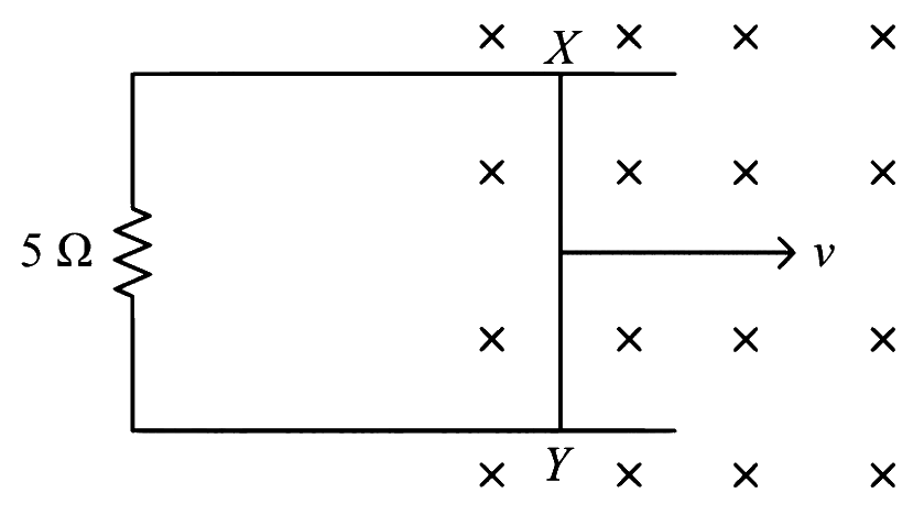
A 1 m long metal rod XY completes the circuit as shown in figure. The plane of the circuit is perpendicular to the magnetic field of flux density 0.15 T. If the resistance of the circuit is 5Ω, the force needed to move the rod in direction, as indicated, with a constant speed of 4 m/s will be ____________ 10−3 N.
Numerical answer type. Work it out, then open the answer.
Motional EMF · Earth's field, aeroplane and falling wire
A metallic rod of length 20 cm is placed in North-South direction and is moved at a constant speed of 20 m/s towards East. The horizontal component of the Earth's magnetic field at that place is 4 × 10⁻³ T and the angle of dip is 45∘. The emf induced in the rod is ___________ mV.
Numerical answer type. Work it out, then open the answer.
Show answer and solution
Answer: 16
Rod N–S moving east: BH (north) is along the rod, so it gives no emf; only BV is cut.
Motional EMF · Straight conductor and moving loops
A straight conductor of length 0.6 M is moved with a speed of 10 ms−1 perpendicular to magnetic field of induction 1.2 weber m −2. The induced e.m.f. across the conductor is
Motional EMF · Force, power and work on a moving rod
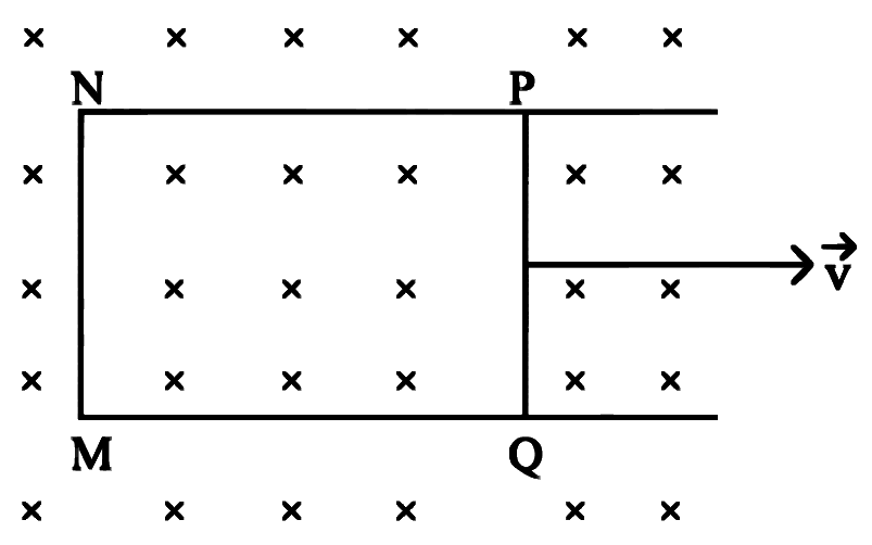
A rectangular loop PQMN with movable arm PQ of length 12 cm and resistance 2Ω is placed in a uniform magnetic field of 0.1 T acting perpendicular to the plane of the loop as shown in figure. The resistances of the arms MN, NP and MQ are negligible. The current induced in the loop when arm PQ is moved with velocity 20 ms−1 is
Motional EMF · Straight conductor and moving loops
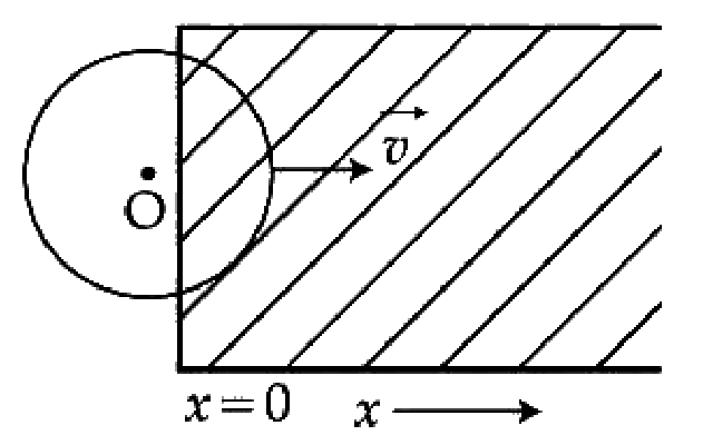
A constant magnetic field of 1T is applied in the x > 0 region. A metallic circular ring of radius 1m is moving with a constant velocity of 1 m/s along the x-axis. At t = 0s, the centre of O of the ring is at x = −1m. What will be the value of the induced emf in the ring at t = 1s? (Assume the velocity of the ring does not change.)
Show answer and solution
Answer: (c)
At t=1 s the centre is at x=−1+1=0, on the field boundary.
The ring cuts the boundary along a diameter: effective length =2R=2 m.
Motional EMF · Earth's field, aeroplane and falling wire
A wire of length 'L'; having resistance 'R' falls from a height 'ℓ' in earth's horizontal magnetic field 'B'. The current through the wire is ( g= acceleration due to gravity)
Motional EMF · Earth's field, aeroplane and falling wire
A metal wire of length 2500 m is kept in east-west direction, at a height of 10 m from the ground. If it falls freely on the ground then the current induced in the wire is (Resistance of wire =252Ω,g=10 m/s2 and Earth's horizontal component of magnetic field BH=2×10⁻⁵ T)
Motional EMF · Earth's field, aeroplane and falling wire
An aeroplane, with its wings spread 10 m, is flying at a speed of 180 km/h in a horizontal direction. The total intensity of earth's field at that part is 2.5 × 10⁻⁴ Wb/m2 and the angle of dip is 60∘. The emf induced between the tips of the plane wings will be __________.
Show answer and solution
Answer: (d)
Horizontal wings cut the vertical component: BV=Bsinδ=2.5×10⁻⁴×sin60∘=2.165×10⁻⁴ T.
Motional EMF · Force, power and work on a moving rod
A wire of length 1 m is moving at a speed of 2 m/s perpendicular homogenous magnetic field of 0.5 T. The ends of the wire are joined to resistance 6Ω. The rate at which work is being done to keep the wire moving at that speed is
Show answer and solution
Answer: (b)
e=Blv=0.5×1×2=1 V
At constant speed, mechanical power = electrical power P=Re2.
Motional EMF · Force, power and work on a moving rod
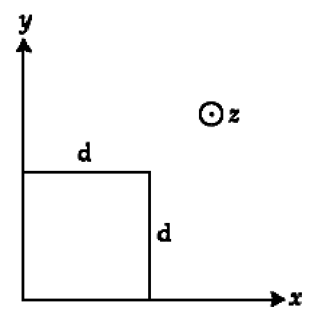
The magnetic field in a region is given by B=Bo(ax)k^. A square loop of side d is placed with its edges along the x and y axes. The loop is moved with a constant velocityv= v0i^. The emf induced in the loop is:
Show answer and solution
Answer: (d)
Sides parallel to x give no net emf; each side parallel to y (length d) has emf Bdv0.
Left side at x: B1=B0ax; right side at x+d: B2=B0ax+d.
The two emfs oppose, so e=(B2−B1)dv0=aB0d⋅dv0
Motional EMF · Force, power and work on a moving rod
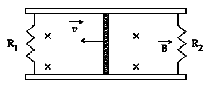
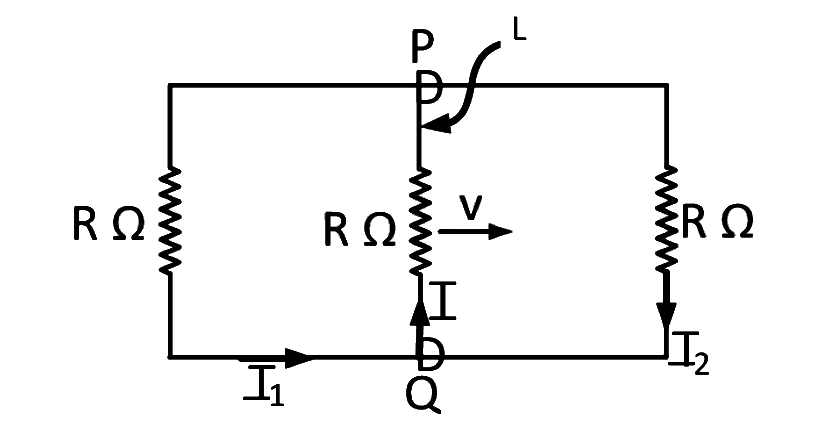
A conducting bar of length L is free to slide on two parallel conducting rails as shown in the figure
Two resistors R1 and R2 are connected across the ends of the rails. There is a uniform magnetic field B pointing into the page. An external agent pulls the bar to the left at a constant speed v. The correct statement about the directions of induced currents I1 and I2 flowing through R1 and R2 respectively is:
Show answer and solution
Answer: (b)
Bar moves left with B into the page: force on + charge qv×B points down the bar.
So current flows downward in the bar.
Left loop (R1): bar is its right side, downward current there means clockwise (also: its inward flux decreases, so induced current is clockwise).
Right loop (R2): bar is its left side, downward current there means anticlockwise (its inward flux increases).
So the answer is (b) I1 clockwise, I2 anticlockwise.
Motional EMF · Straight conductor and moving loops
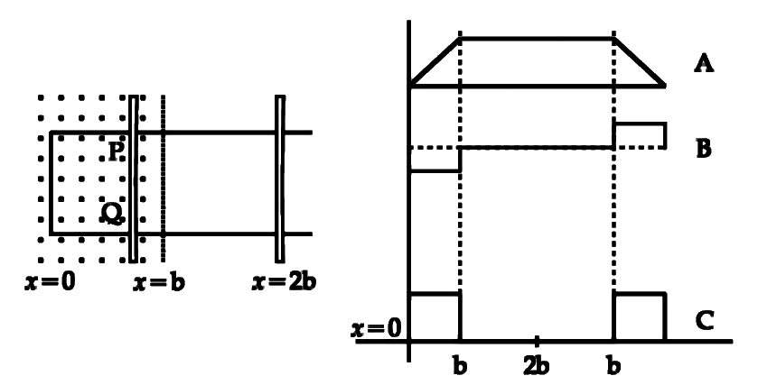
The arm PQ of a rectangular conductor is moving from x = 0 to x = 2b outwards and then inwards from x = 2b to x = 0 as shown in the figure. A uniform magnetic field perpendicular to the plane is acting from x = 0 to x = b. Identify the graph showing the variation of different quantities with distance.
Show answer and solution
Answer: (b)
Flux: rises linearly from 0 to b (area in field grows), stays constant from b to 2b and back to b, then falls to zero. This is graph A.
EMF =−dtdϕ: constant while going out (0 to b), zero outside the field, constant with opposite sign while coming back. This is graph B.
Power =Re2: same positive value in both field stretches, zero elsewhere. This is graph C.
So the answer is (b) A-Flux, B-EMF, C-Power dissipated.
Motional EMF · Force, power and work on a moving rod
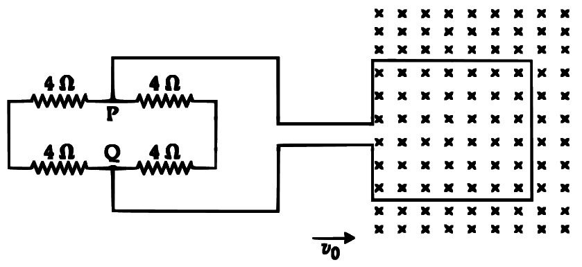
A square loop of side 20 cm and resistance 1Ω is moved towards right with a constant speed v0. The right arm of the loop is in a uniform magnetic field of 5T. The field is perpendicular to the plane of the loop and is going into it. The loop is connected to a network of resistors each of value 4Ω. What should be the value of v0 so that a steady current of 2 mA flows in the loop?
Show answer and solution
Answer: (b)
Only the right arm is in the field: e=Blv0=5×0.2×v0=v0
Between P and Q there are two paths, each 4+4=8Ω, in parallel: RPQ=4Ω.
Motional EMF · Force, power and work on a moving rod
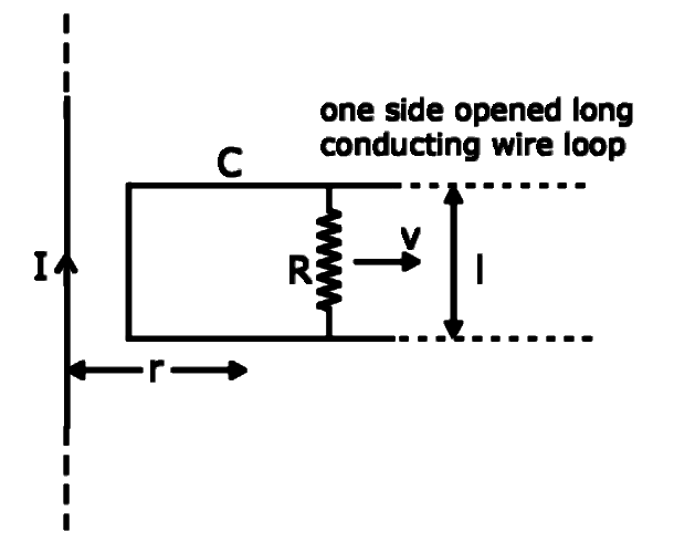
An infinitely long, straight wire carrying current I, one side opened rectangular loop and a conductor C with a sliding connector are located in the same plane, as shown, in the figure. The connector has length l and resistance R. It slides to the right with a velocity v. The resistance of the conductor and the self inductance of the loop are negligible. The induced current in the loop, as a function of separation r, between the connector and the straight wire is:
Show answer and solution
Answer: (c)
Field of the long wire at the connector: B=2πrμ0I
Motional EMF · Straight conductor and moving loops
A solid metal cube of edge length 2 cm is moving in a positive y-direction at a constant speed of 6 m/s. There is a uniform magnetic field of 0.1 T in the positive z-direction. The potential difference between the two faces of the cube perpendicular to the x-axis, is -
Show answer and solution
Answer: (b)
Force on charges qv×B: j^×k^=i^, so charges separate along x.
In equilibrium the faces normal to x have V=Bvd, with d = edge.
Motional EMF · Earth's field, aeroplane and falling wire
A 10 m long horizontal wire extends from North East to South West. It is falling with a speed of 5.0 ms–1, at right angles to the horizontal component of the earth's magnetic field of 0.3 × 10⁻⁴ Wb/m2. The value of the induced emf in wire is:
Show answer and solution
Answer: (d)
BH points north; only the wire's component perpendicular to it (east–west) matters.
Motional EMF · Force, power and work on a moving rod
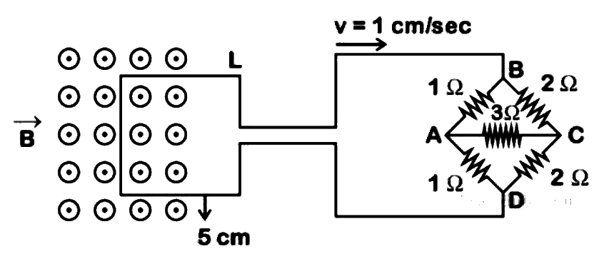
The figure shows a square loop L of side 5 cm which is connected to a network of resistances. The whole setup is moving towards right with a constant speed of 1 cm s-1. At some instant, a part of L is in a uniform magnetic field of 1 T, perpendicular to the plane of the loop. If the resistance of L is 1.7 Ω, the current in the loop at that instant will be close to:
Show answer and solution
Answer: (b)
emf in loop: e=Blv=1×0.05×0.01=5×10⁻⁴ V
Bridge fed at B and D is symmetric top-bottom, so A and C are at the same potential: no current in the 3Ω.
RBD=(1+1)∥(2+2)=62×4=34Ω
Total R=1.7+1.33=3.03Ω, I=3.035×10⁻⁴≈1.65×10⁻⁴ A≈170μA
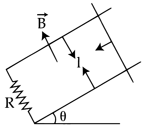
A copper rod of mass m slides under gravity on two smooth parallel rails, with separation l and set at an angle of θ with the horizontal. At the bottom rails are joined by a resistance R. There is a uniform magnetic field B normal to the plane of the rails, as shown in the igure. The terminal speed of the copper rod is:
Show answer and solution
Answer: (c)
Gravity component along the rails: mgsinθ.
B is normal to the rails' plane, so e=Blv, I=RBlv, and drag force F=BIl=RB2l2v up the incline.
Motional EMF · Straight conductor and moving loops
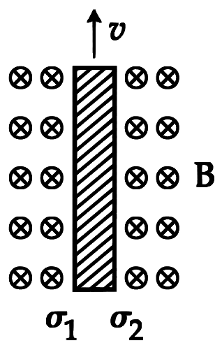
Consider a thin metallic sheet perpendicular to the plane of the paper moving with speed ‘v’ in a uniform magnetic field B going into the plane of the paper (See figure). If charge densities σ1 and σ2 are induced on the left and right surfaces, respectively, of the sheet then (ignore fringe effects):
Show answer and solution
Answer: (a)
Force on + charge: qv×B with v up and B into the page points to the left.
So the left surface becomes positive and the right surface negative.
Equilibrium inside: qE=qvB⇒E=vB.
Field between two opposite charged surfaces: E=ϵ0σ⇒σ=ϵ0vB
Q176JEE Main 2016 · 10 APR · SHIFT 1DifficultOld syllabus
Motional EMF · Earth's field, aeroplane and falling wire
A fighter plane of length 20 m, wing span (distance from tip of one wing to the tip of the other wing) of 15 m and height 5 m is flying towards east over Delhi. Its speed is 240 ms−1. The earth’s magnetic field over Delhi is 5 × 10⁻⁵ T with the declination angle ~ 0° and dip of θ such that sin θ = 2/3. If the voltage developed is VB between the lower and upper side of the plane and VW between the tips of the wings then VB and VW are close to:
Show answer and solution
Answer: (b)
BV=Bsinθ=5×10−5×32=3.33×10⁻⁵ T, BH=Bcosθ=5×10−5×35=3.73×10⁻⁵ T
Wings (horizontal, along N-S) cut BV: VW=BVlv=3.33×10−5×15×240≈0.12 V=120 mV
Motional EMF · Force, power and work on a moving rod
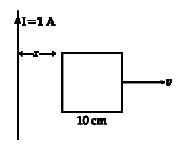
A square frame of side 10 cm and a long straight wire carrying current 1 A are in the plane of the paper. Starting from close to the wire, the frame moves towards the right with a constant speed of 10 ms−1 (see figure). The e.m.f induced at the time the left arm of the frame is at x = 10 cm from the wire is:
Show answer and solution
Answer: (b)
Left arm at x1=0.1 m, right arm at x2=0.2 m; their emfs oppose.
Motional EMF · Earth's field, aeroplane and falling wire
A boat is moving due east in a region where the earth's magnetic field is 5.0×10⁻⁵ N A−1 m−1 due north and horizontal. The boat carries a vertical aerial 2 m long. If the speed of the boat is 1.50 ms−1, the magnitude of the induced emf in the wire of aerial is:
Show answer and solution
Answer: (c)
Aerial is vertical, velocity east, B north: all three mutually perpendicular, so ε=Blv.
Motional EMF · Force, power and work on a moving rod
A rectangular loop has a sliding connector PQ of length l and resistance RΩ and it is moving with a speed v as shown. The set-up is placed in a uniform magnetic field going into the plane of the paper. The three currents I1,I2 and I are
Show answer and solution
Answer: (b)
PQ acts as a cell of emf Blv and internal resistance R.
The two side resistors R are in parallel: 2R.
I=R+R/2Blv=3R2Blv, and it splits equally: I1=I2=3RBlv
Motional EMF · Straight conductor and moving loops
A rectangular, a square, a circular and an elliptical loop, all in the (x-y) plane, are moving out of a uniform magnetic field with a constant velocity. V=vi^. The magnetic field is directed along the negative z axis direction. The induced emf, during the passes of these loops, out of the field region, will not remain constant for
Show answer and solution
Answer: (a)
ε=Bℓv, where ℓ is the length of the loop cut by the field boundary at that instant.
Rectangle and square: the boundary cuts a constant width, so emf is constant.
Circle and ellipse: the chord at the boundary changes with time, so emf changes.
So the answer is (a) the circular and the elliptical loops.
Motional EMF · Straight conductor and moving loops
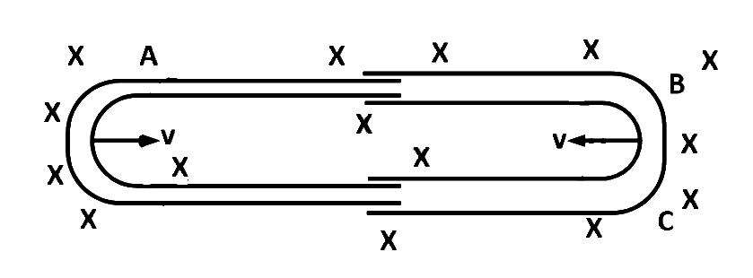
One conducting U tube can slide inside another as shown in figure, maintaining electrical contacts between the tubes. The magnetic field B is perpendicular to the plane of the figure. If each tube moves towards the other at a constant speed v, then the emf induced in the circuit in terms of B,l and v where l is the width of each tube, will be
Show answer and solution
Answer: (c)
Both closed ends move towards each other, so the loop length shrinks at rate 2v.
Motional EMF · Straight conductor and moving loops
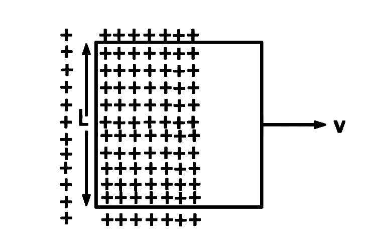
A conducting square loop of side L and resistance R moves in its plane with a uniform velocity v perpendicular to one of its sides. A magnetic induction B constant in time and space, pointing perpendicular and into the plane at the loop exists everywhere with half the loop outside the field, as shown in figure. The induced emf is
Show answer and solution
Answer: (d)
Only the left side (length L) lies in the field; as the loop moves the area inside the field changes at rate Lv.
Motional EMF · Straight conductor and moving loops
A straight line conductor of length 0.4 m is moved with a speed of 7 m/s perpendicular to a magnetic field of intensity 0.9 Wb/m2. The induced e.m.f. across the conductor is
A conductor of length 1 m rotates vertically about one of its ends at angular velocity 5 rad/s. If the horizontal component of earth's magnetic field is 0.2×10⁻⁴ T, then the e.m.f. developed between the ends of the conductor is
Show answer and solution
Answer: (c)
Rod rotating about one end: e=21Bωl2, with B the field normal to the plane of rotation (BH here).
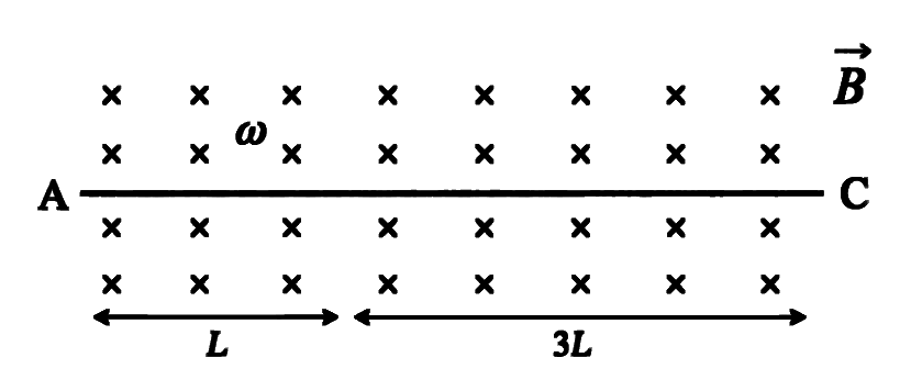
A conducting rod AC of length 4L is rotated counter-clockwise about a point O in a uniform magnetic field B directed into the paper. If AO=L and OC=3L then (ω = angular speed)
Show answer and solution
Answer: (c)
For a rod rotating about a pivot, the emf between the pivot and a point at distance r is 21Bωr2.
With B into the page and counter-clockwise rotation, qv×B pushes positive charge towards O, so O is at the higher potential.
A conducting rod AB of length l is rotated about point O which lies between point A and B in a uniform magnetic field B directed into the paper. If length AO=3l, then (VA−VB) is {ω= angular velocity}
Show answer and solution
Answer: (c)
Emf between pivot O and a point at distance r: 21Bωr2; both ends are at lower potential than O (same sense).
Rotating Conductors & AC Generator · Rotating coil and ac generator
A conducting circular loop is rotated about its diameter at a constant angular speed of 100 rad/s in a magnetic field of 0.5 T perpendicular to the axis of rotation. When the loop is rotated by 30∘ from the horizontal position, the induced EMF is 15.4 mV. The radius of the loop is ______ mm. ( Take π=722)
Numerical answer type. Work it out, then open the answer.
Show answer and solution
Answer: 14
Starting from the horizontal position (plane perpendicular to B): e=BAωsinθ.
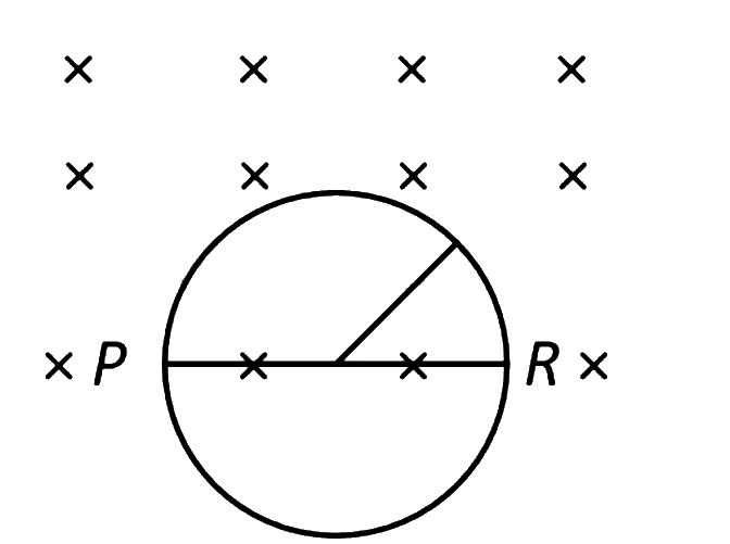
A metal rod of length L rotates about one end at origin with a uniform angular velocity ω. The magnetic field radially falls off as B(r)=Boe−λr;λ being a positive constant. The emf induced (neglecting the centripetal force on electrons in the rod) is:
Show answer and solution
Answer: (a)
Element dr at distance r moves with speed ωr: de=B(r)ωrdr.
e=Boω∫0Lre−λrdr
Integrating by parts: ∫0Lre−λrdr=λ21−e−λL(λL+λ21)
Rotating Conductors & AC Generator · Wheel and disc
A uniform magnetic field of 0.4 T acts perpendicular to a circular copper disc 20 cm in radius. The disc is having a uniform angular velocity of 10 π rad s-1 about an axis through its centre and perpendicular to the disc. What is the potential difference developed between the axis of the disc and the rim? (π=3.14)
Rotating Conductors & AC Generator · Rotating coil and ac generator
A coil of area A and N turns is rotating with angular velocity ω in a uniform magnetic field B about an axis perpendicular to B. Magnetic flux φ and induced emf ε across it, at an instant when B is parallel to the plane of coil, are:
Show answer and solution
Answer: (d)
B parallel to the plane of coil means the area vector is perpendicular to B (θ=90∘).
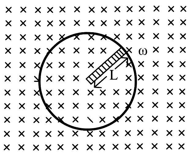
A metal rod of length ' l ' rotates about one of its ends in a plane perpendicular to a magnetic field of induction ' B '. If the e.m.f. induced between the ends of the rod is ' e ', then the number of revolutions made by the rod per second is
A rod of length ' l ' is rotated with angular velocity ' ω ' about its one end, perpendicular to a magnetic field of induction ' B '. The e.m.f. induced in the rod is
Rotating Conductors & AC Generator · Wheel and disc
A metal disc of radius R rotates with an angular velocity ω about an axis perpendicular to its plane passing through its centre in a magnetic field of induction B acting perpendicular to the plane of the disc. The induced e.m.f. between the rim and axis of the disc is
Show answer and solution
Answer: (d)
The disc acts like many radial rods from axis to rim, all in parallel.
A rod of length 60 cm rotates with a uniform angular velocity 20 rad s−1 about its perpendicular bisector, in a uniform magnetic field 0.5 T. The direction of magnetic field is parallel to the axis of rotation. The potential difference between the two ends of the rod is _________ V.
Numerical answer type. Work it out, then open the answer.
Show answer and solution
Answer: 0
Rotating about the perpendicular bisector, each half is a rod of length 2l rotating about the centre.
Each end is at the same potential difference 21Bω(2l)2 from the centre, in the same sense.
So both ends are at the same potential: V1−V2=0 V.
Rotating Conductors & AC Generator · Wheel and disc
A bicycle wheel of radius ' R ' has ' n ' spokes. It is rotating at the rate of ' F ' r.p.m. perpendicular to the horizontal component of earth's magnetic field B. The e.m.f. induced between the rim and the centre of the wheel is
Show answer and solution
Answer: (b)
Each spoke is a rod of length R rotating about one end: e=21BωR2. Spokes are in parallel, so n does not matter.
Rotating Conductors & AC Generator · Rotating coil and ac generator
A circular coil of resistance ' R ', area ' A ', number of turns ' N ' is rotated about its vertical diameter with angular speed ' ω ' in a uniform magnetic field of magnitude ' B '. The average power dissipated in a complete cycle is
Rotating Conductors & AC Generator · Rotating coil and ac generator
A circular coil of resistance R, area A, number of turns ' N ' is rotated about its vertical diameter with angular speed ' ω ' in a uniform magnetic field of magnitude ' B '. The average power dissipated in a complete cycle is
Show answer and solution
Answer: (a)
Induced emf: e=NBAωsinωt, peak e0=NBAω.
Average power: P=R⟨e2⟩=2Re02 since ⟨sin2ωt⟩=21.
Rotating Conductors & AC Generator · Rotating coil and ac generator
A coil of 200 turns and area 0.20 m2 is rotated at half a revolution per second and is placed in uniform magnetic field of 0.01 T perpendicular to axis of rotation of the coil. The maximum voltage generated in the coil is β2π volt. The value of β is _______.
Numerical answer type. Work it out, then open the answer.
Rotating Conductors & AC Generator · Wheel and disc
A ceiling fan having 3 blades of length 80 cm each is rotating with an angular velocity of 1200 rpm. The magnetic field of earth in that region is 0.5 G and angle of dip is 30∘. The emf induced across the blades is Nπ×10−5 V. The value of N is _________.
Numerical answer type. Work it out, then open the answer.
Show answer and solution
Answer: 32
A ceiling fan rotates in a horizontal plane, so only the vertical component acts: BV=Bsin30∘=0.25×10⁻⁴ T.
ω=1200 rpm=20 rev/s=40π rad/s
Emf between centre and tip: e=21BVωl2=21×0.25×10−4×40π×0.64
A metallic rod of length 'L' is rotated with an angular speed of 'ω' normal to a uniform magnetic field 'B' about an axis passing through one end of rod as shown in figure. The induced emf will be:
Show answer and solution
Answer: (b)
Each element dx at distance x has speed ωx: de=Bωxdx.
A 20 cm long metallic rod is rotated with 210 rpm about an axis normal to the rod passing through its one end. The other end of the rod is in contact with a circular metallic ring. A constant and uniform magnetic field 0.2 T parallel to the axis exists everywhere. The emf developed between the centre and the ring is ____________ mV.
Take π=722
Numerical answer type. Work it out, then open the answer.
Rotating Conductors & AC Generator · Wheel and disc
A metal disc of radius R rotates with an angular velocity ω about an axis perpendicular to its plane passing through its centre in a magnetic field of induction B acting perpendicular to the plane of the disc. The magnitude of induced emf between the rim and axis of the disc is
Show answer and solution
Answer: (d)
Each radius of the disc behaves like a rod rotating about one end.
Rotating Conductors & AC Generator · Rotating coil and ac generator
An emf is generated by an ac generator having 100 turn coil, of loop area 1 m2. The coil rotates at a speed of one revolution per second and placed in a uniform magnetic field of 0.05 T perpendicular to the axis of rotation of the coil. The maximum value of emf is :-
A metallic conductor of length 1 m rotates in a vertical plane parallel to east-west direction about one of its end with angular velocity 5 rad s−1. If the horizontal component of earth's magnetic field is 0.2 × 10⁻⁴ T, then emf induced between the two ends of the conductor is:
Show answer and solution
Answer: (b)
Plane of rotation is vertical E-W, so the horizontal (northward) component BH is normal to it.
Rotating Conductors & AC Generator · Rotating coil and ac generator
A circular coil of 1000 turns each with area 1m2 is rotated about its vertical diameter at the rate of one revolution per second in a uniform horizontal magnetic field of 0.07T. The maximum voltage generation will be ___________ V.
Numerical answer type. Work it out, then open the answer.
Show answer and solution
Answer: 440
Peak emf of a rotating coil: e0=NBAω, with ω=2πf=2π rad/s.
Rotating Conductors & AC Generator · Rotating coil and ac generator
A circular coil of radius 8.0 cm and 20 turns is rotated about its vertical diameter with an angular speed of 50 rad s−1 in a uniform horizontal magnetic field of 3.0 × 10⁻² T. The maximum emf induced the coil will be ................. × 10−2 volt (rounded off to the nearest integer)
Numerical answer type. Work it out, then open the answer.
Rotating Conductors & AC Generator · Wheel and disc
A wheel with 20 metallic spokes each 1 m long is rotated with a speed of 120 rpm in a plane perpendicular to a magnetic field of 0.4 G. The induced emf between the axle and rim of the wheel will be (1 G=10−4 T)
Show answer and solution
Answer: (b)
Each spoke: e=21BωR2=BπfR2; the number of spokes does not matter (parallel).
Rotating Conductors & AC Generator · Rotating coil and ac generator
An elliptical loop having resistance R, of semi major axis a, and semi minor axis b is placed in magnetic field as shown in the figure. If the loop is rotated about the x-axis with angular frequency ω, the average power loss in the loop due to Joule heating is:
Show answer and solution
Answer: (c)
Area of the ellipse A=πab; rotating about the x-axis, ϕ=Bπabcosωt.
Rotating Conductors & AC Generator · Rotating coil and ac generator
A planar loop of wire rotates in a uniform magnetic field. Initially at t = 0, the plane of the loop is perpendicular to the magnetic field. If it rotates with a period of 10 s about an axis in its plane then the magnitude of induced emf will be maximum and minimum, respectively at:
Show answer and solution
Answer: (d)
At t=0 the plane is perpendicular to B: ϕ=BAcosωt, so e=BAωsinωt.
ω=102π: ∣e∣ is maximum when ωt=2π, i.e. t=2.5 s.
Rotating Conductors & AC Generator · Rotating coil and ac generator
A circular coil of radius 10 cm is placed in a uniform magnetic field of 3.0 × 10⁻⁵ T with its plane perpendicular to the field initially. It is rotated at constant angular speed about an axis along the diameter of coil and perpendicular to magnetic field so that it undergoes half of rotation in 0.2 s. The maximum value of EMF induced (in μV) in the coil will be close to the integer _______.
Numerical answer type. Work it out, then open the answer.
Show answer and solution
Answer: 15
Half rotation in 0.2 s, so T=0.4 s and ω=0.42π=5π rad/s.
Rotating Conductors & AC Generator · Wheel and disc
A cycle wheel of radius 0.5 m is rotated with constant angular velocity of 10 rad/s in a region of magnetic field of 0.1 T which is perpendicular to the plane of the wheel. The EMF generated between its centre and the rim is,
Show answer and solution
Answer: (c)
Each spoke is a rod rotating about one end; spokes are in parallel, so the emf is that of one spoke.
Rotating Conductors & AC Generator · Rotating coil and ac generator
A coil of cross-sectional area A having n turns is placed in a uniform magnetic field B. When it is rotated with an angular velocity ω, the maxium e.m.f. induced in the coil will be:
A metallic rod of length ′ℓ′ is tied to a string of length 2ℓ and made to rotate with angular speed ω on a horizontal table with one end of the string fixed. If there is a vertical magnetic field ′B′ in the region, the e.m.f induced across the ends of the rod is
Show answer and solution
Answer: (d)
The rod lies between distances 2ℓ and 3ℓ from the fixed point of rotation.
A metal conductor of length 1 m rotates vertically about one of its ends at angular velocity 5 radians per second. If the horizontal component of earth's magnetic field is 0.2×10⁻⁴ T, then the e.m.f. developed between the two ends of the conductor is
Show answer and solution
Answer: (b)
Rotating about one end in a vertical plane, the rod cuts BH: e=21BHωl2
Rotating Conductors & AC Generator · Rotating coil and ac generator
In a uniform magnetic field of induction B a wire in the form of a semicircle of radius r rotates about the diameter of the circle with an angular frequency ω. The axis of rotation is perpendicular to the field. If the total resistance of the circuit is R, the mean power generated per period of rotation is
Show answer and solution
Answer: (b)
Area of the semicircle A=2πr2, so peak emf e0=BAω=2Bπr2ω.
The current flowing through an inductor of self-inductance L is continuously increasing at constant rate. The variation of induced e.m.f. (e) versus time t is shown graphically by
Show answer and solution
Answer: (d)
Self-induced emf: e=−LdtdI.
dtdI is a positive constant, so e is a constant negative value at all times.
The graph is a horizontal line below the time axis.
Two coils A and B have 180 and 360 turns respectively. The current of 1A flows through both the coils. Due to current of 1A in coil A, flux per turn of 0.8×10⁻³ Wb is linked with coil A. Due to current of 1A in coil B, flux per turn of 1×10⁻³ Wb is linked with coil B. The self inductance of coil A is LA and the self inductance of coil B is LB. The ratio LA to LB is
Show answer and solution
Answer: (b)
Self-inductance L=INϕ (flux per turn ϕ).
LA=1180×0.8×10−3=0.144 H, LB=1360×1×10−3=0.36 H
The current flowing through the inductor of self inductance 'L' is continuously increasing at constant rate. The variation of induced e.m.f. (e) versus dtdI is shown graphically by figure
Show answer and solution
Answer: (c)
e=−LdtdI: e is directly proportional to dtdI with a negative constant −L.
The graph is a straight line through the origin going into negative e.
Self-Inductance & Energy · L of a solenoid and its dependence
The self inductance of an air-core inductor (solenoid) is 0.03 mH. By introducing an iron core into inductor the self-inductance increases to 30 mH. The relative permeability of the core used is
Self-Inductance & Energy · L of a solenoid and its dependence
Consider a long solenoid of length l and radius r. If n is the number of turns per unit length and μ0 is the permeability of free space, the inductance of the solenoid is:
Self-Inductance & Energy · L of a solenoid and its dependence
A solenoid is connected to a battery so that a steady current flows through it. If an iron core is inserted into the solenoid, then the current in the coil
Show answer and solution
Answer: (c)
Inserting the iron core raises μr, so L and the flux through the coil increase.
By Lenz's law a back emf −LdtdI (from the rising flux) opposes the battery while the core is moving in.
So the current falls while the core is being inserted (it returns to V/R once the core stops).
Self-Inductance & Energy · L of a solenoid and its dependence
Two solenoids A and B of equal number of turns have their lengths and radii in the same ratio 1:3. The ratio of the self-inductance of solenoid A to that of B will be
Self-Inductance & Energy · L of a solenoid and its dependence
A 30 cm long solenoid has 10 turns per cm and area of 5 cm2. The current through the solenoid coil varies from 2 A to 4 A in 3.14 s. The e.m.f. induced in the coil is α×10−5 V. The value α is ______.
Self-Inductance & Energy · Energy stored in an inductor
The self induced e.m.f. of a coil is 25 V. When the current in it is changed at uniform rate from 10 A to 25 A in 1 s, the change in the energy of the inductance is
Self-Inductance & Energy · Energy stored in an inductor
Two different coils have self-inductance 3L and L. The current in both the coils is increased at the same constant rate. At certain instant of time, the power given to the two coils is same. At that time there was current and voltage induced in the two coils. At the same instant, the ratio of energy stored in the first coil to that in the second coil is
Show answer and solution
Answer: (b)
Power to a coil P=eI=LIdtdI; same P and same dtdI give L1I1=L2I2.
Self-Inductance & Energy · Energy stored in an inductor
Two coils have self inductance L1 and L2. The current through them is increasing at constant rate. If the power dissipated in both the coils is same, then the ratio of energy stored in the coil having inductance L1 to that in L2 is
Show answer and solution
Answer: (d)
P=LIdtdI; equal P and equal rate give L1I1=L2I2, so I2I1=L1L2.
Self-Inductance & Energy · Energy stored in an inductor
Inductance of a coil with 104 turns is 10 mH and it is connected to a dc source of 10 V with internal resistance of 10Ω. The energy density in the inductor when the current reaches (e1) of its maximum value is απ×e21 J/m3. The value of α is
______.
(μ0=4π×10−7 Tm/A).
Numerical answer type. Work it out, then open the answer.
Show answer and solution
Answer: 20
Maximum current I0=1010=1 A, so I=e1 A.
Energy density u=2μ0B2 with B=μ0nI, so u=2μ0n2I2.
Taking n=104 turns per metre: u=24π×10−7×10⁸×e21=20π×e21 J/m3
When a current in the conducting coil is changed from 5 A in one direction to 5 A in opposite direction in 0.5 second, an average induced e.m.f in the coil is 2 V. The selfinductance of the coil is
The current flowing through an inductor of selfinductance L is continuously increasing at constant rate. The variation of induced e.m.f. (e) verses dI/dt is shown graphically by figure
Show answer and solution
Answer: (b)
e=−LdtdI: e is directly proportional to dtdI with a negative constant −L.
The graph must be a straight line through the origin going into negative e.
Self-Inductance & Energy · L of a solenoid and its dependence
A coil is wound on a core of rectangular cross-section. If all the linear dimensions of core are increased by a factor 3 and number of turns per unit length of coil remains same, the self- inductance increases by a factor
Show answer and solution
Answer: (d)
L=μ0n2Al with n (turns per unit length) fixed, so L∝Al.
Self-Inductance & Energy · L of a solenoid and its dependence
To manufacture a solenoid of length ' l ' and inductance ' L ', the length of the thin wire required is (Diameter of the solenoid is very less than length, μ0= permeability of free space)
Self-Inductance & Energy · Energy stored in an inductor
Two inductors of 80 mH each are joined in parallel. The current passing through the combination is 2.1 A. The energy stored in this combination of inductors is
Self-Inductance & Energy · Energy stored in an inductor
Two circuits A and B are connected to identical d.c. sources each of e.m.f. 10 volt. Self-inductances of circuits A and B are respectively LA=10 H and LB=10 mH. The total resistance of each circuit is 40Ω. The ratio of energy consumed in circuit A and circuit B to build up the current to steady value is
Show answer and solution
Answer: (b)
Steady current in both: I=RE=4010=0.25 A.
Energy stored in building up the current: U=21LI2, so U∝L for the same I.
Self-Inductance & Energy · Energy stored in an inductor
When three inductors of same inductance ' L ' are connected in series and ' I ' is the current passing through the circuit. The energy stored in the circuit is
A current of 0.5 A is passed through winding of a long solenoid having 400 turns. The magnetic flux linked with each turn is 3×10⁻³ Wb. The self inductance of the solenoid is
The current in an inductor is given by I=(3t+8) where t is in second. The magnitude of induced emf produced in the inductor is 12 mV. The self-inductance of the inductor _________ mH.
Numerical answer type. Work it out, then open the answer.
Self-Inductance & Energy · L of a solenoid and its dependence
A coil is wound on a core of rectangular crosssection. If all the linear dimensions of the core are increased by a factor 2 and number of turns per unit length of coil remains same, the self inductance increases by a factor of (Assume, permeability is same)
Self-Inductance & Energy · L of a solenoid and its dependence
An air cored coil has a self inductance 0.1 H. A soft iron core of relative permeability 1000 is introduced and the number of turns is reduced (101)th. The value of self inductance is
Self-Inductance & Energy · L of a solenoid and its dependence
A closely wound coil of 100 turns and of cross-section 1 cm2 has coefficient of self inductance 1 mH. The magnetic induction at the centre of the core of a coil when a current of 2 A flows in it, will be (in Wb/m2)
Self-Inductance & Energy · L of a solenoid and its dependence
An air cored coil has self inductance of 0.1 H. A soft iron core of relative permeability 1000 is introduced and the number of turns is reduced to (101)th. The value of self inductance is now
Self-Inductance & Energy · L of a solenoid and its dependence
Let us consider two solenoids A and B, made from same magnetic material of relative permeability μr and equal area of cross-section. Length of A is twice that of B and the number of turns per unit length in A is half that of B. The ratio of self inductances of the two solenoids, LA:LB is
A long solenoid has 1500 turns. When a current of 3.5 A flows through it, the magnetic flux linked with each turn of solenoid is 2.8×10⁻³ weber. The self-inductance of solenoid is
When a current of 1 A is passed through a coil of 100 turns, the flux associated with it is 2.5×10⁻⁵ Wb/ turn. The self inductance of the coil in millihenry is
Self-Inductance & Energy · L of a solenoid and its dependence
The self induction (L) produced by solenoid of length 'l' having 'N' number of turns and cross sectional area 'A' is given by the formula (ϕ= magnetic flux, μ0= permeability of vacuum)
Show answer and solution
Answer: (c)
Field inside: B=lμ0NI; total flux linkage Nϕ=NBA=lμ0N2AI.
12 V battery connected to a coil of resistance 6Ω through a switch, drives a constant current in the circuit. The switch is opened in 1 ms. The emf induced across the coil is 20 V. The inductance of the coil is:
Show answer and solution
Answer: (c)
Steady current I=RV=612=2 A, falls to 0 in 1 ms.
Self-Inductance & Energy · L of a solenoid and its dependence
Inductance per unit length near the middle of a long solenoid is (μ0= permeability of free space, n= number of turns per unit length, d= the diameter of the solenoid)
Self-Inductance & Energy · L of a solenoid and its dependence
To manufacture a solenoid of length 1 m and inductance 1 mH, the length of thin wire required is (cross - sectional diameter of a solenoid is considerably less than the length)
Self-Inductance & Energy · Energy stored in an inductor
Two inductors of 60 mH each are joined in parallel. The current passing through this combination is 2.2 A. The energy stored in this combination of inductors in joule is
A 10 Ω, 20 mH coil carrying constant current is connected to a battery of 20 V through a switch. Now after switch is opened current becomes zero in 100 μs. The average e.m.f. induced in the coil is ____________ V.
Numerical answer type. Work it out, then open the answer.
Self-Inductance & Energy · Energy stored in an inductor
The current in a coil of self inductance 2.0 H is increasing according to I = 2 sin(t2) A. The amount of energy spent during the period when current changes from 0 to 2 A is ____________ J.
Numerical answer type. Work it out, then open the answer.
Show answer and solution
Answer: 4
Energy spent in raising the current = energy stored, U=21LI2 (it depends only on the final current).
Self-Inductance & Energy · Energy stored in an inductor
. If the current of 'I' A gives rise to a magnetic flux 'ϕ' through a coil having 'N' turns then mangetic energy stored in the medium surrounding the coil is
Self-Inductance & Energy · Energy stored in an inductor
A coil of inductance 2 H having negligible resistance is connected to a source of supply whose voltage is given by V = 3t volt. (where t is in second). If the voltage is applied when t = 0, then the energy stored in the coil after 4 s is _______J.
Numerical answer type. Work it out, then open the answer.
In a fluorescent lamp choke (a small transformer) 100 V of reverse voltage is produced when the choke current changes uniformly from 0.25 A to 0 in a duration of 0.025 ms. The self-inductance of the choke (in mH) is estimated to be ________.
Numerical answer type. Work it out, then open the answer.
Self-Inductance & Energy · L of a solenoid and its dependence
The length of solenoid is I whose windings are made of material of density D and resistivity ρ. The winding resistance is R. The inductance of solenoid is [m= mass of winding wire, μ0= permeability of free space]
Show answer and solution
Answer: (a)
With wire length w: L=4πIμ0w2 (from L=Iμ0N2πr2 and w=2πrN).
Wire cross-section a: R=aρw and m=Dwa, so Rm=ρDw2.
Self-Inductance & Energy · L of a solenoid and its dependence
The total number of turns and cross-section area in a solenoid is fixed. However, its length L is varied by adjusting the separation between windings. The inductance of solenoid will be proportional to:
Self-Inductance & Energy · L of a solenoid and its dependence
A copper wire is wound on a wooden frame, whose shape is that of an equilateral triangle. If the linear dimension of each side of the frame is increased by a factor of 3, keeping the number of turns of the coil per unit length of the frame the same, then the self inductance of the coil:
Show answer and solution
Answer: (d)
The wire is wound around the bars of the frame, like a solenoid bent along the triangle: L=μ0n2Al.
Here A is the cross-section of the frame bar (unchanged) and l is the total wound length (perimeter).
Self-Inductance & Energy · Energy stored in an inductor
The self induced emf of a coil is 25 volts. When the current in it is changed at uniform rate from 10 A to 25 A in 1s, the change in the energy of the inductance is -
A long solenoid has 1000 turns. When a current of 4 A flows through it, the magnetic flux linked with each turn of the solenoid is 4 ×10⁻³ Wb. The self-inductance of the solenoid is
A long solenoid has 500 turns. When a current of 2 ampere is passed through it, the resulting magnetic flux linked with each turn of the solenoid is 4 × 10⁻³ Wb. The self-inductance of the solenoid is
The current in self inductance L=40 mH is to be increased uniformly from 1 amp to 11 amp in 4 milliseconds. The e.m.f. induced in inductor during process is
Two coils P and Q are separated by some distance. When a current of 3 A flows through coil P, a magnetic flux of 10−3 Wb passes through Q. No current is passed through Q. When no current passes through P and a current of 2 A passes through Q, the flux through P is x×10−3 Wb. The value of x is
Show answer and solution
Answer: (b)
Mutual inductance is the same both ways: M=IPΦQ=310−3 H.
Consider two coils in which a current in one coil carrying 6 A causes the change in the flux in the second coil 12×10−4 weber/turn. The second coil has 2000 turns. The mutual inductance between the coils is
Two coils have a mutual inductance of 0.005 H. The current changes in the first coil according to equation I=I0sinωt, where I0=10 A and ω=60π rad s−1. The maximum values of e.m.f. in the second coil in volt will be
The coefficient of mutual induction is 3H and induced e.m.f. across secondary is 4 kV. Current in primary is reduced from 7A to 2A. The time required for the change of current is
Alternating current of peak value (π2) A flows through the primary coil of a transformer. The coefficient of mutual inductance between primary and secondary coils is 1 H. The peak em.f. induced in secondary coil is (Frequency of a. c. is 50 Hz)
Two coils of self inductance, 2 mH and 8 mH are placed so closed together that the effective flux in one coil is completely linked with the other. The mutual inductance between these coils is,
Show answer and solution
Answer: (d)
Complete flux linkage means coupling coefficient k=1, so M=L1L2
Two coils having self-inductance L1=75 mH and L2=48 mH are coupled with each other. If the mutual inductance of the coils is 37.2 mH, then coefficient of coupling will be
Mutual Inductance · Concentric loops and coaxial solenoids
Two conducting circular loops of radii r1 and r2 are placed in the same plane with their centres coinciding. If r1≫r2, then the mutual inductance M between them is proportional to [I1= current flowing through coil 1 and I2= current flowing through coil 2]
Show answer and solution
Answer: (c)
Field at centre of big loop: B=2r1μ0I1, nearly uniform over the small loop since r1≫r2
Flux through small loop: Φ=Bπr22=2r1μ0πr22I1
Mutual Inductance · Concentric loops and coaxial solenoids
Two conducting circular loops of radii r and 2r are placed in the same plane with their centres coinciding. The mutual inductance M between them is {same current is passing through both the coils} (μ0= permeability of free space)
Show answer and solution
Answer: (b)
Using the small-inner-loop result M=2r1μ0πr22 with r1=2r, r2=r
Mutual Inductance · Concentric loops and coaxial solenoids
Two planar concentric rings of metal wire having radii 'r1' and 'r2' (with r1>r2) are placed in air. The current 'I' is flowing through the coil of larger radius. The mutual inductance between the coils is given by ( μ0 = permeability of free space)
Show answer and solution
Answer: (b)
Field of larger ring at centre: B=2r1μ0I, taken uniform over the smaller ring
Mutual Inductance · Concentric loops and coaxial solenoids
A circular coil of radius 'r' is placed on another circular coil whose radius is 'R' and the current flowing through it is changing and their centers coincide. (R≫r). If both the coils are coplanar, then the mutual inductance between them is proportional to
Show answer and solution
Answer: (d)
Field of big coil at centre: B=2Rμ0I, uniform over the small coil (R≫r)
Mutual Inductance · Concentric loops and coaxial solenoids
Two concentric circular coils having radii r1 and r2 (r2≪r1) are placed co-axially with centres coinciding. The mutual inductance of the arrangement is (Both coils have single turn, μ0 = permeability of free space)
Show answer and solution
Answer: (d)
Field of outer coil at centre: B=2r1μ0I, uniform over inner coil since r2≪r1
Mutual Inductance · Concentric loops and coaxial solenoids
A circular current loop of radius R is placed inside square loop of side length L (L≫R) such that they are co-planar and their centers coincide. The permeability of free space is μ0. The mutual inductance between circular loop and square loop is ______.
Show answer and solution
Answer: (d)
Field at the centre of a square loop (current I, side L): each side gives 4π(L/2)μ0I(sin45∘+sin45∘).
B=4×2πLμ0I2=πL22μ0I
Since R≪L, B is uniform over the small loop: ϕ=BπR2=L22μ0IR2
Suppose a long solenoid of 100 cm length, radius 2 cm having 500 turns per unit length, carries a current I=10sin(ωt) A, where ω=1000 rad/s. A circular conducting loop (B) of radius 1 cm coaxially slided through the solenoid at a speed v=1 cm/s. The r.m.s. current through the loop when the coil B is inserted 10 cm inside the solenoid is 2αμA. The value of α is ______. [Resistance of the loop =10Ω ]
Show answer and solution
Answer: (d)
Inside a long solenoid B=μ0nI is uniform, so sliding the loop does not change flux; only I(t) does.
ϕ=μ0nI0sinωtπr2, so e0=μ0nI0ωπr2
e0=4π×10−7×500×10×1000×π×10−4=2π2×10⁻⁴≈1.974×10⁻³ V
Two coils P and Q are kept near each other. When no current flows through coil P and current increases in coil Q at the rate 10 A/s, the emf in coil P is 12 mV. When coil Q carries no current and current of 1.5 A flows through coil P, the magnetic flux linked with the coil Q in mWb is
Show answer and solution
Answer: (d)
M=dIQ/dteP=1012×10−3=1.2×10−3 H
Same M both ways: ΦQ=MIP=1.2×10−3×1.5=1.8×10⁻³ Wb
Two coils P and Q are kept near each other. When no current flows through coil P and current increases in coil Q at the rate of 10 A/s, the e.m.f. in coil P is 15 mV. When coil Q carries no current and current of 1.8 A flows through coil P, the magnetic flux linked with coil Q is
The coefficient of mutual induction is 2 H and induced e.m.f. across secondary is 2 kV. Current in the primary is reduced from 6 A to 3 A. The time required for the change of current is
Mutual Inductance · Concentric loops and coaxial solenoids
Two planar concentric rings of metal wire having radii r1 and r2(r1>r2) are placed in air. The current I is flowing through the coil of larger radius. The mutual inductance between the coils is given by ( μ0= permeability of free space)
Show answer and solution
Answer: (b)
Field of larger ring at centre: B=2r1μ0I, taken uniform over the smaller ring
Mutual Inductance · Concentric loops and coaxial solenoids
Two conducting circular loops of radii R1 and R2 are placed in the same plane with their centres coinciding. If R1>R2, the mutual inductance M between them will be directly proportional to
Show answer and solution
Answer: (d)
Field of loop R1 at centre: B=2R1μ0I, taken uniform over loop R2
Consider I1 and I2 are the currents flowing simultaneously in two nearby coils 1 & 2, respectively. If L1 = self inductance of coil 1, M12 = mutual inductance of coil 1 with respect to coil 2, then the value of induced emf in coil 1 will be:
The coefficient of mutual induction is 2 H and induced e.m.f. across secondary is 2 kV. Current in the primary is reduced from 6 A to 3 A. The time required for the change of current is
Two coils have a mutual inductance 0.003 H. The current changes in the first coil according to equation I=I0sinωt, where I0=8 A and ω=100π rad s−1. The maximum value of e.m.f. in the second coil is
Two coils have a mutual inductance 5×10⁻³ H. The current changes in the first coil according to the equation I1=I0sinωt where I0=10 A and ω=100π rad/s. What is the value of the maximum e.m.f. in the coil?
Two coils are kept near each other. When no current passes through first coil and current in the 2nd coil increases at the rate 10 A/s, the e.m.f. in the 1st coil is 20 mV. When no current passes through 2nd coil and 3.6 A current passes through 1st coil the flux linkage in coil 2 is
Show answer and solution
Answer: (d)
M=dI2/dte1=1020×10−3=2×10−3 H
M12=M21=M, so flux linkage in coil 2: Φ2=MI1=2×10−3×3.6
Two coils have mutual inductance 0.002 H. The current changes in the first coil according to the relation i=i0sinωt, where i0=5 A and ω=50π rad/s. The maximum value of emf in the second coil is απ V. The value of α is _______.
Numerical answer type. Work it out, then open the answer.
The mutual inductance of two coils is 45 mH. The self-inductance of the coils are L1=75 mH and L2=48 mH. The coefficient of coupling between the two coils is
Two coils of self-inductance 25 mH and 9 mH are placed close together such that the effective flux in one coil is completely linked with the other The mutual inductance between these coils is
Mutual Inductance · Concentric loops and coaxial solenoids
Two concentric circular coils having radii ' r1 and ' r2 ' (r2≪r1) are placed co-axially with centres coinciding. The mutual inductance of the arrangement is ( μ0= permeability of free space) (Both coils have single turn)
Show answer and solution
Answer: (d)
Field of outer coil at centre: B=2r1μ0I, uniform over inner coil since r2≪r1
Mutual Inductance · Concentric loops and coaxial solenoids
The planar concentric rings of metal wire having radii r1 and r2 (with r1>r2) are placed in air. The current I is flowing through the coil of larger radius. The mutual inductance between the coils is given by ( μ0= permeability of free space)
Show answer and solution
Answer: (d)
Field of larger ring at centre: B=2r1μ0I, taken uniform over the smaller ring
Mutual Inductance · Concentric loops and coaxial solenoids
Two conducting circular loops A and B are placed in the same plane with their centres coinciding as shown in figure. The mutual inductance between them is:
Show answer and solution
Answer: (b)
From the figure, inner loop A has radius a, outer loop B has radius b≫a.
Current I in B gives at the centre B0=2bμ0I, nearly uniform over A
The number of turns in the primary of a transformer are 1000 and in secondary 3000. If 80 V a.c. is applied to the primary, the potential difference per turn of the secondary coil is
Show answer and solution
Answer: (c)
VpVs=NpNs⇒Vs=80×10003000=240 V
Voltage per turn =3000240=0.08 V (same as 80/1000 for the primary)
Mutual Inductance · Concentric loops and coaxial solenoids
A small square loop of wire of side l is placed inside a large square loop of wire of side L(L=l2). The loops are coplanar and their centers coincide. The value of the mutual inductance of the system is x×10−7 H, where x= _________.
Numerical answer type. Work it out, then open the answer.
Show answer and solution
Answer: 128
For a small square inside a large square (centres coinciding): M=πL22μ0l2
Two coils have a mutual inductance of 0.004 H. The current changes in the first coil according to equation I=I0sinωt, where I0=10 A and ω=50π rad s−1. The maximum value of e.m.f. in the second coil in volt is
Two coils A and B have mutual inductance 0.008 H. The current changes in the coil A, according to the equation I=Imsinωt, where Im=5 A and ω=200π rad s−1. The maximum value of the e.m.f. induced in the coil B in volt is
The mutual inductance (M) of the two coils is 3 H. The self inductances of the coils are 4 H and 9 H respectively. The coefficient of coupling between the coils is
Mutual Inductance · Concentric loops and coaxial solenoids
A coil of radius 'r' is placed on another coil (whose radius is R and current flowing through it is changing) so that their centres coincide (R≫r). If both the coils are coplanar then the mutual inductance between them is ( μ0= permeability of free space)
Show answer and solution
Answer: (b)
Field of big coil at centre: B=2Rμ0I, uniform over the small coil (R≫r)
Mutual Inductance · Concentric loops and coaxial solenoids
Two concentric circular coils having radii r1 and r2(r2≪r1) are placed co-axially with centres coinciding. The mutual induction of the arrangement is (Both coils have single turn, μ0= permeability of free space)
Show answer and solution
Answer: (a)
Field of outer coil at centre: B=2r1μ0I, uniform over inner coil since r2≪r1
Mutual Inductance · Concentric loops and coaxial solenoids
Two conducting circular loops of radii 'R1' and 'R2' are placed in the same plane with their centres coinciding. If R1>R2, the mutual inductance M between them will be directly proportional to
Show answer and solution
Answer: (d)
Field of loop R1 at centre: B=2R1μ0I, taken uniform over loop R2
A transformer has 20 turns in the primary and 100 turns in the secondary coil. An ac voltage of Vin =600sin314t is applied to primary terminal of transformer. Then maximum value of secondary output voltage obtained in volt is
The mutual inductance of a pair of coils, each of 'N' turns, is 'M' henry. If a current of 'I' ampere in one of the coils is brought to zero in 't' second, the e. m. f. induced per turn in the other coil in volt is
Show answer and solution
Answer: (a)
M is defined by total flux linkage: Nϕ2=MI, so total emf in the other coil e=MtI
Emf per turn =Ne=NtMI
So the working gives (d) NtMI; the key gives (a) tMI, which is the total emf of the coil.
Mutual Inductance · Concentric loops and coaxial solenoids
Find the mutual inductance in the arrangement, when a small circular loop of wire of radius 'R' is placed inside a large square loop of wire of side L(L≫R). The loops are coplanar and their centres coincide:
Show answer and solution
Answer: (c)
Field at the centre of the square loop: B=4×4π(L/2)μ0I×2sin45∘=πL22μ0I
Flux through the small circle (R≪L): ϕ=BπR2=L22μ0IR2
Mutual Inductance · Concentric loops and coaxial solenoids
Two concentric circular coils with radii 1 cm and 1000 cm, and number of turns 10 and 200 respectively are placed coaxially with centers coinciding. The mutual inductance of this arrangement will be ___________ ×10−8 H. (Take, π2=10)
Numerical answer type. Work it out, then open the answer.
Show answer and solution
Answer: 4
Field of the big coil at its centre: B=2r2μ0N2I; flux through the small coil: N1Bπr12.
A square loop of side 2.0 cm is placed inside a long solenoid that has 50 turns per centimetre and carries a sinusoidally varying current of amplitude 2.5 A and angular frequency 700 rad s−1. The central axes of the loop and solenoid coincide. The amplitude of the emf induced in the loop is x×10−4 V. The value of x is __________.
(Take, π=722)
Numerical answer type. Work it out, then open the answer.
Show answer and solution
Answer: 44
B=μ0nI with n=50 per cm=5000 m−1; emf amplitude e0=μ0nI0ωA
Mutual Inductance · Concentric loops and coaxial solenoids
A small square loop of wire of side l is placed inside a large square loop of wire L(L≫l). Both loops are coplanar and their centres coincide at point O as shown in figure. The mutual inductance of the system is:
Show answer and solution
Answer: (c)
Field at the centre of the big square: B=πL22μ0I (four sides, each 4π(L/2)μ0I⋅2sin45∘).
Since l≪L, flux through the small square: ϕ=Bl2=πL22μ0Il2
Mutual Inductance · Concentric loops and coaxial solenoids
A coil of radius 'r' is placed on another coil (whose radius is 'R' and current through it is changing) so that their centres coincide. ( R>r ). If both coplanar, then the mutual inductance between them is proportional to
Show answer and solution
Answer: (d)
Field of big coil at centre: B=2Rμ0I, taken uniform over the small coil
Mutual Inductance · Concentric loops and coaxial solenoids
Two conducting circular loops of radii R1 and R2 are placed in the same plane with their centres coinciding. If R1 >> R2, the mutual inductance M between them will be directly proportional to:
Show answer and solution
Answer: (a)
Field of loop R1 at centre: B=2R1μ0I, uniform over loop R2 since R1≫R2
Mutual Inductance · Concentric loops and coaxial solenoids
A small square loop of side 'a' and one turn is placed inside a larger square loop of side b and one turn (b >> a). The two loops are coplanar with their centres coinciding. If a current I is passed in the square loop of side 'b', then the coefficient of mutual inductance between the two loops is:
Show answer and solution
Answer: (a)
Field at the centre of the big square of side b: B=πb22μ0I
Two coils have a mutual inductance of 0.01 H. The current in the first coil changes according to equation, I=5sin200πt. The maximum value of emf induced in the second coil is
Two coils 'P' and 'Q' are separated by some distance. When a current of 3 A flows through coil 'P', a magnetic flux of 10–3 Wb passes through 'Q'. No current is passed through 'Q'. When no current passes through 'P' and a current of 2 A passes through 'Q', the flux through 'P' is :-
Mutual Inductance · Concentric loops and coaxial solenoids
There are two long co-axial solenoids of same length l. The inner and outer coils have radii r1 and r2 and number of turns per unit length n1 and n2, respectively. The ratio of mutual inductance to the self - inductance of the inner-coil is:
Show answer and solution
Answer: (b)
Mutual inductance: field of outer coil μ0n2I links the inner coil, so M=μ0n1n2πr12l.
Mutual Inductance · Concentric loops and coaxial solenoids
At the center of a fixed large circular coil of radius R, a much smaller circular coil of radius r is placed. The two coils are concentric and are in the same plane. The larger coil carries a current I. The smaller coil is set to rotate with a constant angular velocity ω about an axis along their common diameter. Calculate the emf induced in the smaller coil after a time t of its start of rotation.
Show answer and solution
Answer: (a)
Field at the centre: B=2Rμ0I, uniform over the small coil.
Mutual Inductance · Concentric loops and coaxial solenoids
A small circular loop of wire of radius a is located at the centre of a much larger circular wire loop of radius b. The two loops are in the same plane. The outer loop of radius b carries an alternating current I = Io cos (ωt). The emf induced in the smaller inner loop is nearly:
Show answer and solution
Answer: (a)
Field at the centre of the big loop: B=2bμ0I, nearly uniform over the small loop.
Two coils, X and Y, are kept in close vicinity of each other. When a varying current, I(t), flows through coil X, the induced emf (V(t)) in coil Y, varies in the manner shown here. The variation of I(t), with time, can then be represented by the graph labelled as graph:
(A)
(B)
(C)
(D)
Show answer and solution
Answer: (b)
V=−MdtdI, so the slope of I(t) is opposite in sign to V and proportional to it.
First part: V>0, starting and ending at zero, so I falls with zero slope at both ends (a smooth cosine-like fall).
Second part: V is a negative constant, so I rises linearly.
After that V=0, so I stays constant. Only graph C has this shape.
A circular loop of radius 0.3 cm lies parallel to a much bigger circular loop of radius 20 cm. The center of the small loop is on the axis of the bigger loop. The distance between their centers is 15 cm. If a current of 2.0 A flows through the smaller loop, then the flux linked with bigger loop is
Show answer and solution
Answer: (a)
Use M12=M21: find flux through the small loop when current I flows in the big loop.
On the axis: B=2(R2+x2)3/2μ0IR2, with R=0.2, x=0.15: (R2+x2)3/2=0.06253/2=0.015625
M=2(R2+x2)3/2μ0R2πr2=0.031254π×10−7×0.04×π×9×10−6≈4.55×10−11 H
Mutual Inductance · Concentric loops and coaxial solenoids
Two coaxial solenoids are made by winding thin insulated wire over a pipe of cross-sectional area A=10 cm2 and length =20 cm. If one of the solenoid has 300 turns and the other 400 turns, their mutual inductance is
(μ0=4π×10−7 T m A−1)
Show answer and solution
Answer: (d)
For coaxial solenoids on the same pipe: M=lμ0N1N2A
Two coils of self inductance 2 mH and 8 mH are placed so close together that the effective flux in one coil is completely linked with the other. The mutual inductance between these coils is
Two coils have a mutual inductance of 0.005 H. The current changes in the first coil according to equation I=I0sinωt, where I0=10 A and ω=100π rad/s. The maximum value of emf in the second coil is
Combination of Inductors, LR & LC Circuits · Series and parallel inductors
Two inductors, L1 and L2 are connected in parallel and a time varying current flows as shown in the figure. The ratio of currents I1I2 at any time, it is
Show answer and solution
Answer: (b)
In parallel both inductors have the same voltage: L1dtdI1=L2dtdI2
Combination of Inductors, LR & LC Circuits · Series and parallel inductors
Two inductors, L1 and L2, are connected in parallel and time-varying current flows the combination. If I1 and I2 are the currents passing through the inductor L1 and L2 respectively, the ratio I1I2 is
Show answer and solution
Answer: (b)
Parallel inductors have equal emf: L1dtdI1=L2dtdI2, so L1I1=L2I2
Combination of Inductors, LR & LC Circuits · Series and parallel inductors
Three coils of inductance, L1 = 2 H, L2 = 3 H and L3 = 6 H are connected so that they are separated from each other. To obtain the effective inductance of 1118 H between points A and B, out of the following figures, the correct one is
Combination of Inductors, LR & LC Circuits · Series and parallel inductors
Two identical inductors are connected in two different configurations P and Q, where a time varying current I(t) is flowing, as shown in the figure. The induced emf between points a and b for configuration P is EP and that for configuration Q is EQ. The ratio EP/EQ is:
[Neglect the effect of mutual inductance.]
Show answer and solution
Answer: (a)
In P, a and b are across only the top inductor: EP=LdtdI
In Q, a and b are across the parallel pair: EQ=2LdtdI
Combination of Inductors, LR & LC Circuits · LR growth and decay
The following figure represents two bulbs B1 and B2, resistor R and an inductor L. When the switch S is turned off, which of the following statement is true?
Show answer and solution
Answer: (c)
When S is opened, the battery is cut off, but R–B1 and L–B2 still form one closed loop.
The inductor keeps the current flowing and it decays as e−t/τ around this loop.
The same current passes through both bulbs, so both go off together after the same delay.
Combination of Inductors, LR & LC Circuits · LR growth and decay
An inductor of inductance 10 mH having resistance of 100Ω is connected to battery of E.M.F. 1.0 V through a switch as shown in the figure below. After switch is closed, the ratio of instantaneous voltages across the inductor when the current passing through it is 2 mA and 4 mA is ______.
Combination of Inductors, LR & LC Circuits · LR growth and decay
Figure shows the circuit that contains three resistances ( 9Ω each) and two inductors ( 4 mH each). The reading of ammeter at the moment switch K is turned ON, is ______ A.
Show answer and solution
Answer: (c)
At the instant of switching on, an inductor blocks current (acts as an open circuit).
Combination of Inductors, LR & LC Circuits · LR growth and decay
In the given circuit below inductance values of L1,L2 and L3 are same. The magnetic energy stored in the entire circuit is (Ut) and that stored in the L2 inductor is (Ul)⋅Ut/Ul is ______. (Ignore the mutual inductance if any)
Numerical answer type. Work it out, then open the answer.
Show answer and solution
Answer: 6
L1 carries the full current I; L2 and L3 are equal and in parallel, so each carries I/2.
Combination of Inductors, LR & LC Circuits · Potential difference across an inductor
In the circuit shown, when the current 'i' is 3A and increasing at the rate of 1A/s the measurement of the potential difference between A and B is 12 V. But when the same current 3A is decreasing at the rate of 1A/s, the measured potential difference VAB between A and B is 6V. The value of 'R' in the circuit is
Show answer and solution
Answer: (a)
Current flows from A through R and L to B, so VAB=iR+Ldtdi.
Combination of Inductors, LR & LC Circuits · Series and parallel inductors
Two identical coils of inductance L joined in series are placed very close to each other such that the winding direction of one coil is exactly opposite to that of the other. The net inductance is
Combination of Inductors, LR & LC Circuits · Potential difference across an inductor
AB is a part of an electrical circuit (see figure). The potential difference " VA−VB ", at the instant when current i=2 A and is increasing at a rate of 1 amp/ second is:
Show answer and solution
Answer: (b)
Go from A to B along i: VA−Ldtdi−5−iR=VB (battery crossed from + to −).
Combination of Inductors, LR & LC Circuits · Potential difference across an inductor
In the given circuit the sliding contact is pulled outwards such that electric current in the circuit changes at the rate of 8 A/s. At an instant when R is 12Ω, the value of the current in the circuit will be ________ A.
Numerical answer type. Work it out, then open the answer.
Show answer and solution
Answer: 3
Pulling the contact out increases R, so current decreases: dtdI=−8 A/s.
Combination of Inductors, LR & LC Circuits · Series and parallel inductors
Three coils of inductance L1=2 H,L2=3 H and L3=6 H are connected such that they are separated from each other. To obtain the effective inductance of 1 henry, out of the following combinations as shown in figure, the correct one is
Combination of Inductors, LR & LC Circuits · LR growth and decay
Three identical resistors with resistance R = 12Ω and two identical inductors with self inductance L = 5 mH are connected to an ideal battery with emf of 12 V as shown in figure. The current through the battery long after the switch has been closed will be _____________ A.
Numerical answer type. Work it out, then open the answer.
Show answer and solution
Answer: 3
Long after closing, di/dt=0, so each inductor acts as a plain wire.
The three branches then each have resistance R=12Ω, all in parallel: Req=12/3=4Ω.
Combination of Inductors, LR & LC Circuits · Series and parallel inductors
Two coils of self inductance L1 and L2 are connected in series combination having mutual inductance of the coils as M. The equivalent self inductance of the combination will be:
Show answer and solution
Answer: (d)
In the figure the current flows through the two coils in opposite senses, so their mutual fluxes oppose the self fluxes.
Combination of Inductors, LR & LC Circuits · LR growth and decay
An inductor coil stores 64 J of magnetic field energy and dissipates energy at the rate of 640 W when a current of 8A is passed through it. If this coil is joined across an ideal battery, find the time constant of the circuit in seconds:
Combination of Inductors, LR & LC Circuits · LR growth and decay
Figure shows a circuit that contains four identical resistors with resistance R = 2.0Ω, two identical inductors with inductance L = 2.0 mH and an ideal battery with emf E = 9V. The current 'i' just after the switch 'S' is closed will be:
Show answer and solution
Answer: (d)
Just after closing S, both inductor branches carry no current (inductors act as open circuits).
Current flows only through the series R and the single R branch: total 2R=4Ω.
Combination of Inductors, LR & LC Circuits · LC oscillation
A circuit has self-inductance 'L' H and carries a current 'I' A. To prevent sparking when the circuit is switched off, a capacitor which can withstand 'V' volt is used. The least capacitance of the capacitor connected across the switch must be equal to
Show answer and solution
Answer: (c)
On switching off, the magnetic energy of the inductor must be taken up by the capacitor.
Combination of Inductors, LR & LC Circuits · LR growth and decay
A shown in the figure, a battery of emf ε is connected to an inductor L and resistance R in series. The switch is closed at t = 0. The total charge that flows from the battery, between t = 0 and t = tc (tc is the time constant of the circuit) is:
Combination of Inductors, LR & LC Circuits · LR growth and decay
A 20 Henry inductor coil is connected to a 10 ohm resistance in series as shown in figure. The time at which rate of dissipation of energy (joule's heat) across resistance is equal to the rate at which magnetic energy is stored in the inductor is:
Show answer and solution
Answer: (c)
Condition: i2R=Lidtdi, i.e. iR=Ldtdi (voltage across R = voltage across L).
Combination of Inductors, LR & LC Circuits · LR growth and decay
An ideal coil of 10 H is connected in series with a resistance of 5Ω and a battery of 5 V⋅2 second after the connection is made, the current flowing in ampere in the circuit is
Combination of Inductors, LR & LC Circuits · LR growth and decay
An inductor (L=100 mH), a resistor (R=100Ω) and a battery (E=100 V) are initially connected in series as shown in the figure. After a long time the battery is disconnected after short circuiting the points A and B. The current in the circuit 1 ms after the short circuit is
Show answer and solution
Answer: (a)
Steady current before shorting: I0=E/R=100/100=1 A.
After shorting, the current decays: i=I0e−t/τ with τ=L/R=0.1/100=1 ms.
An electron (mass m) is accelerated through a potential difference of 'V' and then it enters in a magnetic field of induction 'B' normal to the lines. The radius of the circular path is (e= electronic charge)
Statement I: If the number of turns in the coil of a moving coil galvanometer is doubled then the current sensitivity becomes double.
Statement II: Increasing current sensitivity of a moving coil galvanometer by only increasing the number of turns in the coil will also increase its voltage sensitivity in the same ratio In the light of the above statements, choose the correct answer from the options given below:
Show answer and solution
Answer: (a)
Current sensitivity Iθ=kNAB, so doubling N doubles it: Statement I is true.
Voltage sensitivity Vθ=kRNAB; doubling N also doubles the wire length, so R doubles and voltage sensitivity stays the same: Statement II is false.
Two coaxial solenoids of different radius carry current I in the same direction. F1 be the magnetic force on the inner solenoid due to the outer one and F2 be the magnetic force on the outer solenoid due to the inner one. Then:
Show answer and solution
Answer: (c)
The field of the inner solenoid is zero outside it, so the outer solenoid feels no force: F2=0.
The outer solenoid's field inside is uniform and axial; on the inner coil's circular turns the forces Idl×B are radial and cancel around each turn.